Advertisement
Quick Links
Taper Grip
®
Introduction
The keyless Taper-Grip® bushing system provides simple and reliable
shaft attachment for Sumitomo Speed reducers and gearmotors. This
system allows bi-directional shaft rotation and stop-start operation with
a powerful, slip-free grip. To assure peak performance of your equip-
ment, please read, understand and follow these installation instructions.
Safety
Disconnect all power sources from the equipment before beginning this
installation procedure. Handle the components with care and avoid all
sharp or machined edges to prevent personal injury or damage to the
components.
Before Installing Unit on Driven Shaft
(Steps 1-7)
Carefully inspect the driven equipment shaft. Remove all burrs, corrosion,
lubricants, and foreign matter from the shaft surface. Verify the shaft
diameter is within the dimensional tolerances shown in Table 1.
Table 1 Driven Shaft Tolerances
Shaft Diameter (inches)
3/4" – 1-1/8"
1-3/16" – 2"
2-1/16" – 3-1/8"
3-3/16" – 4-3/4"
4-13/16" – 6-1/2"
Clean all surfaces of the shaft, the bushing, the thrust collar and the unit
bore with solvent to remove all grease and oil.
Step 1 – Remove the Taper-Grip® bushing safety cover (see Fig. 2).
Step 2 – Remove the cap screws from the bushing. Lightly oil the
threads of the cap screws and partially re-insert them into the threaded
holes in the bushing flange. The ends of the cap screws should not
extend beyond the rear face of the bushing flange.
Step 3 – Slide the thrust collar onto the Taper-Grip® bushing
(see Fig. 3).
Step 4 – Apply a thin layer of anti-seize paste to the male threads of
the Taper-Grip® Bushing only (see Fig.4). Based on tests, Sumitomo
recommends Bostik Never-Seez Regular Grade or equivalent. Ensure
that anti-seize paste does not enter the Taper-Grip® Bushing bore.
Caution: Do not apply anti-seize paste to the female threads in
the hub.
Step 5 – Carefully thread the Taper-Grip® bushing into the hub of the
speed reducer or gearmotor until the thrust collar solidly engages the
unit hub surface and the bushing flange (see Fig. 5). Caution: Do not
cross-thread. Bushing should thread easily into hub.
Step 6 – Unscrew the Taper-Grip® bushing to create a 1mm (0.04") gap
between the thrust collar and the bushing flange.
Step 7 – Hand-tighten the cap screws until they firmly press the thrust
collar against the unit hub surface. The unit is ready for installation on
the driven shaft.
www.sumitomodrive.com
Bushing Installation Guide
Shaft Tolerance (inches)
+0" – 0.0013"
+0" – 0.0015"
+0" – 0.0018"
+0" – 0.0021"
+0" – 0.0025"
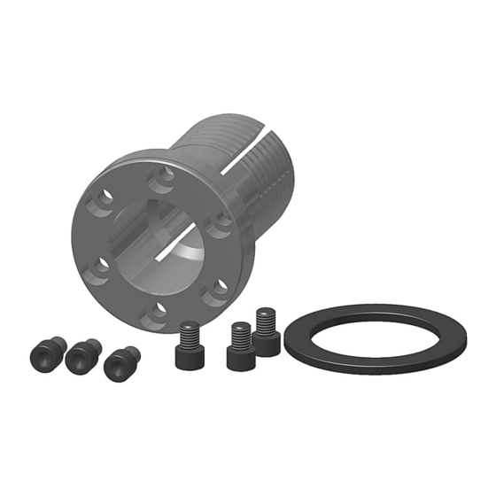
Fig. 1 Taper-Grip® Bushing Parts
Fig. 2 Remove
Safety Cover
Fig. 3 Slide Thrust
Collar on Bushing
Fig. 4 Apply
Anti-seize Paste
Fig. 5 Thread
Bushing into Hub
1-800-SM-CYCLO
Apply thin layer of anti-seize
paste to male threads of
bushing only.
19.001.61.008
Page 1
Advertisement

Related Manuals for Sumitomo Taper Grip


Summary of Contents for Sumitomo Taper Grip
- Page 1 Step 3 – Slide the thrust collar onto the Taper-Grip® bushing (see Fig. 3). Step 4 – Apply a thin layer of anti-seize paste to the male threads of the Taper-Grip® Bushing only (see Fig.4). Based on tests, Sumitomo recommends Bostik Never-Seez Regular Grade or equivalent. Ensure Fig. 4 Apply that anti-seize paste does not enter the Taper-Grip®...
- Page 2 Taper Grip Bushing Installation Guide ® continued Unit Installation Step 8 – Position unit with the bushing flange located on the outboard side of the unit. Align the bushing with the driven shaft. Slide the unit onto the driven shaft as close to the driven shaft support bearing as possible.
- Page 3 Taper Grip Bushing Installation Guide ® continued Removal Procedure Step 1 – Remove the Taper-Grip® bushing safety cover (see Fig. 8). Step 5 – After the liquid penetrant has been allowed to settle, remove the cap screws one at a time (see Fig 12).
- Page 4 World Headquarters www.sumitomodrive.com/worldwide Japan Sumitomo Heavy Industries, Ltd. Power Transmission & Controls Group ThinkPark Tower, 1-1, Osaki 2-chome, Shinagawa-ku, Tokyo 141-6025 Japan Tel: +81-36-737-2511 • Fax: +81-36-866-5160 Manual 19.001.61.008; Supersedes Manual 19.001.61.007 ©2014 Sumitomo Machinery Corporation of America Printed in USA...
Need help?
Do you have a question about the Taper Grip and is the answer not in the manual?
Questions and answers