Table of Contents
Advertisement
Quick Links
Advertisement
Table of Contents

Related Manuals for Huvitz HLM-9000


Summary of Contents for Huvitz HLM-9000
- Page 2 Auto Lensmeter HLM-9000 Service Manual Auto Lensmeter HLM-9000...
-
Page 3: Table Of Contents
INDEX INTRODUCTION ......................... 4 1.1............................. 4 OMPONENTS 1.2............................. 6 EPAIR ROCEDURE 1.3................................7 AUTIONS 1.4............................ 7 OFTWARE VERSION 1.5..............................7 PTICAL YSTEM 1.6..........................9 EASUREMENT RINCIPLE CHECKING AND SETUP METHOD ..................10 2.1..............................10 ETUP RDER 2.2. - Page 4 Auto Lensmeter HLM-9000 3.7. B4_PEN-SLIDE- .......................... 42 ASSEMBLY 3.8. PD-PINION- ..........................44 ASSEMBLY 3.9. B4_FRAME- ..........................46 ASSEMBLY 3.9.1. Removing Lens housing bone and LED subassembly ..........48 ELECTRICAL BLOCK DIAGRAM ....................50 4.1.......................... 50 LECTRICAL BLOCK DIAGRAM 4.2.
-
Page 5: Introduction
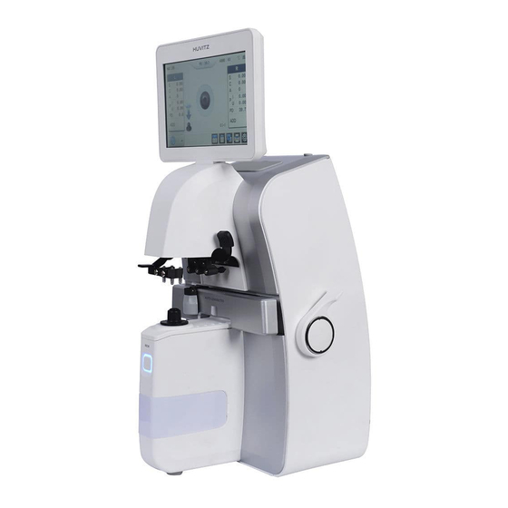
Introduction 1.1. Components List Touch LCD Screen Marking Lever PD Sensor Lens Table Lens Holder Lever Lens Table Lever Lens Cap Printer MEM Button (Save Button) UV, Blue Cover Figure 1. Components Names (I) - Page 6 Auto Lensmeter HLM-9000 Power Switch Figure 2. Components Names (II) RS-232 Connector Power Connector USB Connector Figure 3. Components Names (III)
-
Page 7: Repair Procedure
1.2. Repair Procedure Power ON 1. Examining the Internal Components First 2. Inspecting The value, S.C.A. Prism Normal State Checking Abnormal State Cleaning the Pinhole Power off and on Normal State Checking Abnormal State Setup Again Exit Figure 4. Repair procedure flow chart... -
Page 8: Cautions
Auto Lensmeter HLM-9000 1.3. Cautions Always protect this instrument with Dust Cover after using. Do not vibrate or drop this instrument; it can cause damage. Use soft cloth or cotton swaps with alcohol when clean the pinhole. - Page 9 Signal Receiving Part Hartmann plate : divide the signal into 81 points. Prevent the other light except the signal 2-dimentional CMOS sensor : converts signals into digital value. The lens meter also built optical system for UV and Blue light transmittance. The system is composed of light emitting LED (UV and Blue light) and receiving part (UV and Blue detector).
-
Page 10: Measurement Principle
Auto Lensmeter HLM-9000 1.6. Measurement Principle Basic Principle When there is no lens (0D state), parallel light that has transmitted the collimator lens passes the pinhole and makes image on CCD. In case of convex lens (lens with plus diopter), parallel light that has transmitted the collimator lens converges through the measuring lens, passes the pinhole and then makes image on CCD. -
Page 11: Checking And Setup Method
B. Press three times S or R side (data area). C. Press the user setup (option) button. HLM-9000 will start in setup mode. While this mode, ‘SETUP’ mark will show in the left- upper area. Calibration can be processed only in SETUP mode; LENS, PRISM, CYLINDER, PD, UV&BLUE. -
Page 12: How To Set Origin
Auto Lensmeter HLM-9000 2.2. How to Set Origin The steps of setting origin are as follows: A. Press the ‘LENS’ ( ) button. B. Press the ‘MEASURE’ button. C. Determine the lens to measure by using two ‘-INDEX’, ’+INDEX’ buttons. -
Page 13: How To Set 12 Standard Lenses
2.3. How to Set 12 standard lenses If the measured value is not accurate, you should set the diopter variables again by using the standard lens-set: for all the 12 lenses in the standard lens set. Always keep the standard lens clean out of dust or stain. A. -
Page 14: How To Set Prism
Auto Lensmeter HLM-9000 2.4. How to Set Prism If the measured value is not accurate, you should set the 2, 5, 10, 15, 20 lens again by using the standard lens-set. A. First, convert prism display format into P-B. B. Then, press the ‘PRISM’ ( ) button. -
Page 15: The Calibration Of The Cylindrical Axis
ANGLE PRISM BASE 0° ~ 30° center 31° ~ 60° center 61° ~ 90° center 91° ~ 120° center 121° ~ 150° center 151° ~ 180° center 181° ~ 210° center 211° ~ 240° center 241° ~ 270° center 271° ~ 300° center 301°... - Page 16 Auto Lensmeter HLM-9000 D. ‘-0.01’ button and ‘+0.01’ button by the given value in the standard model-eye specification. E. Locate it to the center while cling it to the lens. (Axis : 90°/135°/180°/45°, Prism_x, y: 0) F. Press the ‘MEASURE’ button and check if ‘A90/A135/A180/A45:’ value is changed.
-
Page 17: Pd Setup
2.6. PD Setup With the PD Sensor, we can calibrate the PD value of our machine. The procedures are as followings: A. Press the ‘PD’ ( ) button. B. Push in the PD sensor is the leftmost. And press the ‘L Lim’ button. C. - Page 18 Auto Lensmeter HLM-9000 D. ‘-0.01’button and ‘+0.01’ button by the given value in the UV lens specification. E. When UV transmissivity is 0.0 : Prevent part that UV-LED comes out. When UV transmissivity is 25.0/50.0/75.0 : Put a lens on the top of the UV-LED comes out..
-
Page 20: Diopter Setting Variables List
Auto Lensmeter HLM-9000 2.8. Diopter Setting Variables List The followings are diopter setting variables list: WAVEFRONT DATA INFORMATION [ALL DIOPTER] 0 [-25.01]: L=+174.59; 123.46, 123.45: average distance and distance rates between the four points and -25D 1 [-19.99]: L=+168.28; 118.99, 119.00: average distance and distance rates between the four points and -20D …... -
Page 21: How To Change The Ccd Camera
2.9. How to change the CCD camera The procedures for changing a camera are as followings. A. Remove all subassemblies that are the side cover, the lens table and the lower cover and the CCD cover etc. B. Loose the Base Screw I and then take out the old CCD assembly. C. - Page 22 Auto Lensmeter HLM-9000 We should place the CMOS Camera keeping two conditions: The first condition is the position of center point. The center position is shown at the 5 row like this. - CEN: (+640.00, +512.00) It must be within ( +640.00 ± 15, 512 ± 15 ) The second one is the orientation of CMOS Camera.
-
Page 23: How To Change The Led Assembly
2.10. How to change the LED Assembly The spare part for the LED assembly is the Upper Frame. So, we provide all upper frame assembly for the LED assembly. The procedures for changing the upper frame Assembly are as followings: A. -
Page 24: How To Change The Pinhole Housing
Auto Lensmeter HLM-9000 2.11. How to change the Pinhole Housing The procedures for changing the Pinhole Housing are as followings: 1. Take out the Lens Supporter. 2. Remove the Pinhole Housing Cover which is the below cover under the Lens Supporter. -
Page 25: Repair Standard
3. Repair Standard 3.1. Removing cover assembly... - Page 26 Auto Lensmeter HLM-9000 Component Removal method - First, extract [12] remove 2 screw on bottom and top side B4_COVER-HANDLE-RING - Next, remove 2 screws on bottom side and 2screw inside MACHINE-SCREW_PH_M3- from [8] and separate [8] 8L_SPW_FW - Separate the [7], [5], [6] step by step,...
-
Page 27: Lcd Ass'y
LCD ass’y 3.2. - Page 28 Auto Lensmeter HLM-9000 Component Removal method - First, remove 4 screws from [7] and separate it. B4_LCD-BASE-PLATE MACHINE-SCREW-PH-M2_6L6-NI - Next, remove 6 screws from [6] and separate it. MACHINE-SCREW-PHW-M3-L6 MACHINE-SCREW-BHW-M2L4-NI - Next, remove 4 screws from [1] Then separate [11]...
-
Page 29: Printer Ass'y
Printer ass’y 3.3. - Page 30 Auto Lensmeter HLM-9000 Component Removal method - First, remove 5 screws from Print Assy’. PAPER-HOLDER Then, separate it from the ‘Cover Left’ INSERT-M2_6D4L4_5 PCB-SUPPORT-M3L8-PLASTIC - Next, remove 3 screws from [10] and separate it. MACHINE-SCREW-BH-M2_6L4-NI TAPPING-SCREW-PH-M2_6L6-NI2 - Be careful that there is no scratch and assembly is the TAPPING-SCREW2-PH-M3L8-NI reverse procedure of disassembly.
-
Page 31: B4_Back-Bone-Assembly
3.4. B4_BACK-BONE-Assembly... - Page 32 Auto Lensmeter HLM-9000 Component Removal method - Disconnect ‘PD Bar Board’ cable from ‘Main Board’. B4_CCD-CAMERA-COVER SHAFT-FIX-BRK - Remove cap [16] B4_BACK-BONE GUIDE-SHAFT-4 - Remove 4 screws on back side of B4_COVER-PD-BAR-ASSY FOOT-MOVING-BLOCK-DAMPER (reference 3.4.1 PD-Bar subassembly) MACHINE-SCREW_FH_M3-5L-NI MACHINE-SCREW_PH_M2-3L - Then, remove 1 screw on back side of [27] from the [3].
-
Page 33: Pd-Bar Subassembly
3.4.1. PD-Bar subassembly... - Page 34 Auto Lensmeter HLM-9000 Component Removal method - To separate the Nose Assembly[20], remove two screws PD-BAR-CABLE-BRK that fix [8]. B4_PD-BAR-PLATE B4_PD-ENCODER-SHAFT-BLOCK - Then, remove four screws from [19] and take off [19]. B4_ENCODER-SHAFT B4_PD-SHAFT - Remove three screws to separate [17].
-
Page 35: B4_Frame-Total- Assembly
3.5. B4_FRAME-TOTAL- assembly... - Page 36 Auto Lensmeter HLM-9000 Component Removal method - Remove 5 screws bottom, front and back side that fix [9] MACHINE-SCREW-PH-M4L5-NI from the ‘Main Frame Assy” MACHINE-SCREW_PH_M3- Then separate it. 8L_SPW_FW MACHINE-SCREW-PHW-M3-L6 Please see the drawing for disassemble, as needed MACHINE-SCREW-BH-M2_6L4-NI WRENCH-BOLT_M3X10L - Assembly is the reverse procedure of disassembly.
-
Page 37: B4_Uv-Bone-Assembly
3.6. B4_UV-BONE-assembly... - Page 38 Auto Lensmeter HLM-9000 Component Removal method - To separate [6], remove 4 screws. B4_UV-BONE MACHINE-SCREW-PH-M2_6L6-NI - To separate [5], remove 2 screws. B4_UV_TEFRON_L B4_UV-TEFRON-U - Assembly is the reverse procedure of disassembly. PCB-ASSY-UVBLUE-LED-101 PCB-ASSY-UVBLUE-SENSOR-101...
-
Page 39: B4_Foot-Frame-Subassembly
3.6.1. B4_FOOT-FRAME-Subassembly... - Page 40 Auto Lensmeter HLM-9000 Component Removal method E-RING-2-SUS Please see the drawing for disassemble, as needed FOOT-HOLDER F_T2_CONTROL_POS_PIN - Assembly is the reverse procedure of disassembly. B4_FOOT-FRAME-BRACKET-13 MACHINE-SCREW_TH_M3-5L POSITION-FOOT-SPRING C7_POSITION-FOOT-RUBBER-ASSY...
-
Page 41: B4_Pen-Frame-Assy
3.6.2. B4_PEN-FRAME-ASSY... - Page 42 Auto Lensmeter HLM-9000 Component Removal method B4_PEN-FRAME-BRK Please see the drawing for disassemble, as needed B4_PEN-PRESS-BRK B4_PEN-CONT-SUPPT - Assembly is the reverse procedure of disassembly. PEN-GUIDE-SHAFT MACHINE-SCREW-FH-M2_6L6-NI WRENCH-M2L6-S WRENCH-BOLT_M3X10L SETSCREW-M3_10L WASHER-M2 E_RING-2_5 B4_PEN-PRESS-BRK-KNOB PEN-GUIDE-SPRING PEN-EXTENSION-SPRING B4_PEN-HOLDER-ASSY...
- Page 43 3.7. B4_PEN-SLIDE- assembly...
- Page 44 Auto Lensmeter HLM-9000 Component Removal method B4_PEN-SLIDE-BASE Please see the drawing for disassemble, as needed MACHINE-SCREW_FH_M3-5L-NI PCB-SUPPORT-M3L5-N - Be careful the balls WRENCH-BOLT_M3X10L SETSCREW-M3L3 - Assembly is the reverse procedure of disassembly. B4_SLIDE-ASSY...
- Page 45 3.8. PD-PINION-assembly...
- Page 46 Auto Lensmeter HLM-9000 Component Removal method Please see the drawing for disassemble, as needed PD-PINION-BRK PD-PINION-SHAFT - Assembly is the reverse procedure of disassembly. PD-PINION-NUT PD-PINION-SHAFT-HOLDER GEAR-WASHER WRENCH-M2L6-S SETSCREW-M3_5L GEAR-L...
- Page 47 3.9. B4_FRAME-assembly...
- Page 48 Auto Lensmeter HLM-9000 Component Removal method Please see the drawing for disassemble, as needed B4_POWER-SW-BRK B4_MAIN-BD-BRACKET - Assembly is the reverse procedure of disassembly. B4_FRAME-LCD-HINGE LCD-CABLE-FIX-BRK MACHINE-SCREW-PH-M3L10-NI MACHINE-SCREW-PHW-M3-L6 PCB-SUPPORT-5 PCB-SUPPORT-M3L10-N PCB-SUPPORT-M3L8-PLASTIC WSFL-M3T0_5-NI FOOT FRAME-CR-RUBBER-1 B4_SMPS-COVER_ Z-A-25-5_SMPS Z-POWER-SWITCH FUSE-INLET-SCHURTER HARNESS_HOLDER Z-RJ45-TR...
- Page 49 3.9.1. Removing Lens housing bone and LED subassembly...
- Page 50 Auto Lensmeter HLM-9000 Component Removal method B4_LED-BONE-13 -Turn part [2] for disassemble lens [4] B4_LED-LENS-NUT-13 Please see the drawing for disassemble, as needed SETSCREW-M3_5L SETSCREW-M3_5L - Assembly is the reverse procedure of disassembly. B4_LED-HOUSING-ASSY-GREEN...
- Page 51 Electrical block diagram 4.1. Electrical block diagram...
- Page 52 Auto Lensmeter HLM-9000...
- Page 53 4.2. Inspecting SMPS Check1. Check if POWER SWITCH and RUG is connected properly. Check2. Check FUSE in POWER SOCKET with DMM. Check1. Is Power LED on in SMPS MODULE? Check2. Check the voltage of DC POWER Cable with DMM. Change SMPS MODULE (It should be AC100 - 220V) *REFERENCE: “ELECTRICAL CONSTRUCTION DIAGRAM”...
- Page 54 Auto Lensmeter HLM-9000 4.3. LCD TEST Measurement screen is not displayed… Check1. SMPS TEST Check1. LCD is bright but there is no Check if CN5 connector of character or figure. LCD is connected correctly to Check2. There are horizontal lines on LCD MAIN BOARD.
- Page 55 4.5. UV & BLUE MODULE TEST Check UV&BLUE-LED states Change UV & BLUE- Check1. Check if violet and blue light radiated from LED PCB ASS’Y OPTIC LED UV&BLUE values in UV&BLUE mode should change(100% -> 0%). Check1. Check if UV&BLUE SENSER in UV&BLUE measurement part is hidden by obstacles such as FILTER COVER.
- Page 56 Auto Lensmeter HLM-9000 4.6. PD TEST PD value is not displayed… Check1. Check right/left switching when you move LEVER Change MAIN right and left compared to the center of PD. BOARD Change PD MODULE...
- Page 57 4.7. THERMAL PRINTER TEST “PRT: HEAD UP” message is displayed on LCD… Check1. Open PRINTER COVER and check if HEADER LEVER towards upside. “PRT: PP EMPTY” message is displayed on LCD when pressing PRINTER BUTTON… Check1. Open PRINTER COVER. Check2.
- Page 58 5. How to upgrade the OS program 5.1. Introduction Downloading program for HLM-9000 with USB cable provide downloading function of the firmware software from PC to Lensmeter. An administrator of the Lensmeter hardware can receive the Firmware by e-mail or else and load it to his/her lensmeter by this downloading program when the new upgrade version of firmware comes out.
- Page 59 5.2. How to upgrade the OS program using DLP application in HLM Machines A. Copy the DSP application files. DSP consists of two files: the executable file (= HFCUSB.exe), the dll files(= cv100.dll, cxcore100.dll and highgui100.dll). It is no need to install it in your desktop computer.
- Page 60 Auto Lensmeter HLM-9000 D. Select ‘USB Controller B’ of ‘Data Received’ display and press ‘Open’ button. Then you can see below screen if connecting is corrected...
- Page 61 E. Check the ‘Status’ which located right side of ‘Open’ button. F. Press ‘File Open (Bin/Bhc)’ button to select upload file.
- Page 62 Auto Lensmeter HLM-9000 G. Press ‘Transmit to HRK/HLM’ button to transmit. H. Then you can see the transmission process on HLM-9000 display. I. Finally turn off and on the machine.
- Page 63 Appendix: Compare HLM-7000 and HLM-9000 Model HLM-7000 HLM-9000 0D ~ ±25D 0D ~ ±25D Sphere (0.01/0.125/0.25) (0.01/0.06/0.12/0.25) 0D ~ ±10D 0D ~ ±10D Cylinder (0.01/0.125/0.25) (0.01/0.06/0.12/0.25) Axis 0° ~ 180° (1° step) 0° ~ 180° (1° step) 0 ~ 10D 0 ~ 10D (0.01/0.125/0.25)
Need help?
Do you have a question about the HLM-9000 and is the answer not in the manual?
Questions and answers