Table of Contents
Advertisement
Advertisement
Table of Contents

Related Manuals for Megger AVO 830


Summary of Contents for Megger AVO 830
- Page 1 830 and AVO ® ® True RMS Digital Multi-Meter User Guide...
-
Page 3: Table Of Contents
Contents Overview Contact Megger UK ............................6 Safety Safety Information ............................7 Measurement Connection ..........................8 Voltage .................................8 CAT IV ................................8 CAT III ................................8 CAT II ................................8 Warnings, Cautions and Notes .........................8 Warnings ...............................8 Cautions ................................8 Notes ................................8 Safety and Hazard Symbols ..........................9 Introduction Measurement Functions ..........................10... - Page 4 Clean the instrument .............................37 Technical Support ............................37 End of Life Disposal WEEE Directive ...............................38 Battery Disposal .............................38 Accessories Optional and Replacement Accessories ......................39 Specifications General Specifications ............................40 Technical Specifications ..........................41 Repair and Warranty Calibration, Service and Spare Parts .......................43 AVO®830 and AVO®835 www.megger.com...
- Page 5 Fig 11: AC voltage Detection Set-up .................... 30 Fig 12: ≤ 10 A Measurement Set-up ..................... 31 Fig 13: ≤ 100 mA Measurement Set-up ..................33 Fig 14: Battery Replacement ......................35 Fig 15: Fuse Replacement ......................36 www.megger.com AVO®830 and AVO®835...
-
Page 6: Overview
Megger digital multi-meter model No. AVO8 Series. For your own safety and to get the maximum benefit from this Megger instrument, read and understand the safety warnings and instructions before the instrument is used. -
Page 7: Safety
The instrument must not be used if any part of it is damaged. „ Use only Megger approved test leads and accessories with this instrument. „ Test leads and probes must be in good order, clean and have no broken or cracked insulation. -
Page 8: Measurement Connection
Safety Measurement Connection Only Megger supplied test leads designed for this instrument provide the full safety rating. Voltage The rated measurement connection voltage is the maximum line to earth voltage at which it is safe to connect. CAT IV Measurement category IV: Equipment connected between the origin of the low-voltage mains supply and the distribution panel. -
Page 9: Safety And Hazard Symbols
DC (Direct Current or Voltage) Overload Fuse Equipment complies with Australian Communications Media Authority (ACMA) requirements for Electro-Magnetic Compatibility (EMC) Equipment complies with current EU directives. Do not dispose of in the normal waste stream. Earth (Ground) www.megger.com AVO®830 and AVO®835... -
Page 10: Introduction
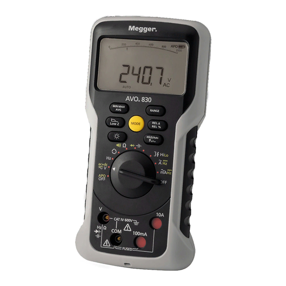
Introduction Introduction The Megger Digital Meters AVO830 and AVO835 are battery powered true-RMS Multi-meters with a 10000 count dual display digital display and analogue arc. They are compact and easy to operate measurement instruments for electrical and electronic applications. These instruments meet the CAT III and CAT IV safety standards. -
Page 11: Product Features
MIN MAX RANGE MODE REL % Low Z HOLD/Auto Ω °C °F ac+dc CAT III 1000V CAT IV 600V Ω 100mA FUSED Details Display (page 15) Function Buttons (page 12) Function Dial (page 13) Terminals (page 14) www.megger.com AVO®830 and AVO®835... -
Page 12: Function Buttons
VAC, VDC, Capacitance and capacitance measurement In LPF (Low Pass Filter) mode the instrument continues to measure in the selected AC mode, but the signal diverts through a filter, which blocks unwanted voltages above 800 Hz AVO®830 and AVO®835 www.megger.com... -
Page 13: Function Dial
Instrument Off (battery power Off) APO is active by default (see Auto Power Off (page 16)) Voltage Measurement (page 18) AC, DC, or AC+DC Phase Rotation / Sequence Detection (page 19) Phase sequence detection of three phase AC supply www.megger.com AVO®830 and AVO®835... -
Page 14: Terminals
CAT III 1000V CAT IV 600V Ω 100mA FUSED Description Details Voltage, Resistance, Diode Capacitance and Voltage Frequency 10 A ≤ 10 A current measurements and frequency 100 mA ≤ 100 mA current measurements and frequency Return (Common) AVO®830 and AVO®835 www.megger.com... -
Page 15: Display
Range: Auto shows when Auto range is selected. Minimum, Maximum or Average modes Primary display Non-contact AC live circuit detection On. Caution, hazardous condition Note: If OL shows on the display it means that the current reading is over range. www.megger.com AVO®830 and AVO®835... -
Page 16: Start-Up Overview
, to toggle through the available ranges. RANGE 2. Press and hold to return to AUTO range (AUTO shows on the display). Backlight Press to set the backlight On or Off. The backlight automatically goes Off after one minute. AVO®830 and AVO®835 www.megger.com... -
Page 17: Measurements
Measurement modes that the not designed to measure live circuits will sound a continuous audible beep and show V OL (flashing) on the display. Measurement is inhibited. Test leads must immediately be disconnected from the circuit under test. www.megger.com AVO®830 and AVO®835... -
Page 18: Voltage Measurement
AUTO range (AC and DC modes only). Low Impedance Voltage Measurements: For AC Voltage measurements on cables with ghost voltage, press Low Z (low input impedance) mode. LoZ will show on the display. AVO®830 and AVO®835 www.megger.com... -
Page 19: Ac+Dc Description
Fig 2: Phase Rotation / Sequence Detection Set-up For a valid detection, set the voltage level and supply frequency to: ACV: > 80 V „ Supply Frequency: In the range 40 Hz to 80 Hz. „ www.megger.com AVO®830 and AVO®835... -
Page 20: Resistance Measurement
Fig 3: Resistance Measurement Set-up Caution: To avoid possible damage to the instrument or to the equipment under test, make sure that the circuit power is disconnected and all high-voltage capacitors are discharged before resistance is measured. AVO®830 and AVO®835 www.megger.com... -
Page 21: Resistance Measurement Tips
The resistance function can produce enough voltage to forward-bias silicon diode or transistor junctions, „ RANGE causing them to conduct. If this is suspected, press to apply a lower current in the next higher range www.megger.com AVO®830 and AVO®835... -
Page 22: Continuity Test
Ω Set the Function Dial to • Red test lead: V terminal • Black test lead: COM terminal • MODE Press to select • 3. Connect the test probes to the cable or circuit under test. AVO®830 and AVO®835 www.megger.com... -
Page 23: Conductance Measurement
Fig 5: Conductance Measurement Set-up Caution: To avoid possible damage to the instrument or to the equipment under test, make sure that the circuit power is disconnected and all high-voltage capacitors are discharged before conductance is measured. www.megger.com AVO®830 and AVO®835... -
Page 24: Capacitance Measurement
Use the DC voltage function to confirm that the capacitor is discharged. To Measure Capacitance 1. Make sure that: The circuit power is disconnected • AVO®830 and AVO®835 www.megger.com... -
Page 25: Smart Capacitance
When the test leads are connected to a capacitor, which has a residual charge, the live circuit is enabled. The Smart Capacitance function monitors the charge status of the capacitor, when the charge status reaches a safe level the instrument will then do a capacitance measurement. www.megger.com AVO®830 and AVO®835... -
Page 26: Diode Test
Note: If a live circuit is detected the instrument will sound a pulsed audible beep and V OL (flashing) shows on the display. 2. Set-up the instrument as shown in Fig 7 for forward or reverse bias. Set the Function Dial to • MODE Press to select • AVO®830 and AVO®835 www.megger.com... -
Page 27: Fig 8: Forward Voltage Drop Across Semi-Conductor Junction
HOLD/Auto HOLD/Auto Ω °C °F Ω °C °F ac+dc ac+dc CAT III 1000V CAT III 1000V CAT IV 600V CAT IV 600V Ω Ω 100mA 100mA FUSED FUSED Fig 8: Forward Voltage Drop Across Semi-conductor Junction www.megger.com AVO®830 and AVO®835... -
Page 28: Frequency Measurement
2. Connect the test probe tips to the circuit under test. The Primary display shows the frequency in Hz. RANGE 3. If manual range is required, press repeatedly to scroll to a suitable range and resolution. Press and RANGE hold to return to AUTO range. AVO®830 and AVO®835 www.megger.com... -
Page 29: Temperature Measurement
Temperature Measurement Probe ‘-’: COM terminal • MODE Press to toggle between °C or °F. OL shows on the Primary display if: The reading is out of range, or „ A sensor is disconnected or open circuit „ www.megger.com AVO®830 and AVO®835... -
Page 30: Ac Voltage Detection
1. Set-up the instrument as shown in Fig 11. Set the Function Dial to • 2. Place the instrument close to a live conductor. MODE 3. Press to select: HI: (default) Highest sensitivity to AC voltage • LO: Low sensitivity to AC voltage • AVO®830 and AVO®835 www.megger.com... -
Page 31: Current Measurement
MODE AVO835 MIN MAX RANGE MODE REL % Low Z HOLD/Auto Ω °C °F ac+dc CAT III 1000V CAT IV 600V Ω 100mA FUSED Fig 12: ≤ 10 A Measurement Set-up www.megger.com AVO®830 and AVO®835... - Page 32 7. If manual range is required, press repeatedly to scroll to a suitable range and resolution. Press and RANGE hold to return to AUTO range. 8. Once the reading is done, disconnect the supply before the test probes are removed. AVO®830 and AVO®835 www.megger.com...
-
Page 33: Milliampere Measurement
4. Make sure that high voltage capacitors are discharged. 5. Connect the test leads in circuit 6. Set the circuit power to On. 7. Once the reading is done, disconnect the supply before the test probes are removed. www.megger.com AVO®830 and AVO®835... - Page 34 Three ranges are available (100 Hz, 1 KHz and 10 KHz). RANGE 4. If manual range is required, press repeatedly to scroll to a suitable range and resolution. Press and RANGE hold to return to AUTO range. AVO®830 and AVO®835 www.megger.com...
-
Page 35: Maintenance
4. Replace the batteries (3). 5. Install the battery cover. Make sure that the gasket (4) is correctly seated. Tighten the two battery cover screws clockwise to secure. 6. Dispose of old batteries (see Battery Disposal (page 38)). www.megger.com AVO®830 and AVO®835... -
Page 36: Fuse Replacement
The screws provided by the manufacturer must be used. 10. Install the batteries. 11. Install the battery cover. Make sure that the gasket (4b) is correctly seated. Tighten the two battery cover captive screws to secure. AVO®830 and AVO®835 www.megger.com... -
Page 37: Clean The Instrument
Wipe the case with a damp cloth and mild detergent „ Technical Support For technical support go to the Megger technical support site (uk.megger.com/support). See the exhaustive FAQs, technical support documents and information about After Sales support. Alternatively: Call +44 (0) 1304 502101 (After Sales support), or „... -
Page 38: End Of Life Disposal
Megger is registered in the UK as a Producer of Electrical and Electronic Equipment (Reg No.: WEE/HE0146QT). For more information about the disposal of this product contact your local Megger company / distributor or go to your local Megger website. -
Page 39: Accessories
Fuse FF 0.125 mA 1000 V 30 kA (6.3 mm x 32 mm) 1009-212 Test Lead Kit (not fused) x2 leads (black/red) 1002-001 x2 crocodile clips (black/red) Test Lead Kit (500 mA) x2 leads (black/red) 1002-015 x2 long probes (black/red) Thermocouple Sensor (AVO835 only) 1010-461 Magnetic Hanger 1010-013 www.megger.com AVO®830 and AVO®835... -
Page 40: Specifications
≤ 50 % at 60 °C (140 °F) Altitude rating 2000 m (6561.5 ft) Battery x2 AA Alkaline (LR6) or x2 NiMH (HR6) Battery life 150 hours (without backlight) IP Rating (dust and water protection) IP54 Category 2 AVO®830 and AVO®835 www.megger.com... -
Page 41: Technical Specifications
≤5 Ω Buzzer Intermittent >5 <50 Ω Buzzer off ≥50 Ω Frequency measurement Range/resolution 100.00 Hz / 0.01 Hz 1.0000 kHz / 0.0001 kHz 10.000 kHz / 0.001 kHz 100.00 kHz / 0.01 kHz Accuracy ±0.1% +2 www.megger.com AVO®830 and AVO®835... - Page 42 Other features Display count 10000 IEC 61010 Safety rating AVO830 - CAT IV 600 V AVO835 - CAT III 1000 V / CAT IV 600 V Dimensions 200 x 100 x 38 mm Weight 430 g AVO®830 and AVO®835 www.megger.com...
-
Page 43: Repair And Warranty
New instruments are covered by a three year warranty from the date of purchase by the user, the second and third year being conditional on the free registration of the product at www.megger.com. You will need to log in, or first register and then login to register your product. The second and third year warranty covers faults, but not recalibration of the instrument which is only warranted for one year. - Page 44 AVO®830 and AVO®835 www.megger.com...
- Page 45 AVO®830 and AVO®835...
- Page 46 AVO®830 and AVO®835 www.megger.com...
- Page 47 AVO®830 and AVO®835...
- Page 48 OTHER TECHNICAL SALES OFFICES Toronto CANADA, Sydney AUSTRALIA, Madrid SPAIN, Mumbai INDIA, and the Kingdom of BAHRAIN. Megger products are distributed in 146 countries worldwide. This instrument is manufactured in the United Kingdom. The company reserves the right to change the specification or design without prior notice.
Need help?
Do you have a question about the AVO 830 and is the answer not in the manual?
Questions and answers