Table of Contents
Advertisement
Quick Links
Advertisement
Chapters
Table of Contents

Related Manuals for Phoenix Contact Nanoline Series


Summary of Contents for Phoenix Contact Nanoline Series
- Page 1 Installing and using Nanoline controllers User manual UM EN NLC...
- Page 2 User manual Installing and using Nanoline controllers 2015-07-15 Designation: UM EN NLC Revision: This user manual is valid for: Designation Version Order No. Nanoline PHOENIX CONTACT 2338_en_O...
- Page 3 How to contact us Internet Up-to-date information on Phoenix Contact products and our Terms and Conditions can be found on the Internet at: phoenixcontact.com Make sure you always use the latest documentation.
- Page 4 The receipt of technical documentation (in particular user documentation) does not consti- tute any further duty on the part of Phoenix Contact to furnish information on modifications to products and/or technical documentation. You are responsible to verify the suitability and intended use of the products in your specific application, in particular with regard to observ- ing the applicable standards and regulations.
-
Page 5: Table Of Contents
Base unit ....................33 Communication.........................35 Serial connections ....................35 3.1.1 RS-232 ....................36 3.1.2 RS-485 ....................37 3.1.3 USB ..................... 37 3.1.4 Memory Module ................... 37 Ethernet communication..................39 3.2.1 LEDs ....................40 3.2.2 Communications watchdog ..............40 2338_en_O PHOENIX CONTACT... - Page 6 Setup ....................80 5.6.6 Memory module ................... 81 Technical appendix........................83 ® Modbus holding registers ................83 Modbus/Nanoline communication ..............86 A 2.1 NLC-050… Modbus map ..............87 A 2.2 NLC-055… Modbus map ..............88 Special formats....................89 PHOENIX CONTACT 2338_en_O...
- Page 7 CDMA modem module (Order No. 2400428) ........119 D 2.13 Base unit option module ..............120 D 2.14 RTC technical specifications (Order No. 2701153) ......120 Conformance/approvals .................. 121 Appendixes..........................123 List of figures ....................123 List of tables ..................... 127 Index......................... 129 2338_en_O PHOENIX CONTACT...
- Page 8 Nanoline PHOENIX CONTACT 2338_en_O...
-
Page 9: Overview
The base unit, communication expansion modules and I/O expansion modules attach to standard NS 35 mounting rail. The type code on each base unit indicates how the base unit is equipped. See Figure 1-2 for an explanation of the type codes. 2338_en_O PHOENIX CONTACT... -
Page 10: Nanoline Base Unit
In addition to the I/O points located on the base unit, I/O expansion modules (NLC-IO-…) can be connected to the base unit to provide additional connection points. Different I/O modules provide different combinations and types of I/O. PHOENIX CONTACT 2338_en_O... -
Page 11: Communication Expansion Modules
Slot 1, and option modules intended for Slot 2 must only be inserted in Slot 2. Each slot is labeled on the face of the base unit, and each option module includes a numeric indicator to indicate which slot is acceptable. 2338_en_O PHOENIX CONTACT... -
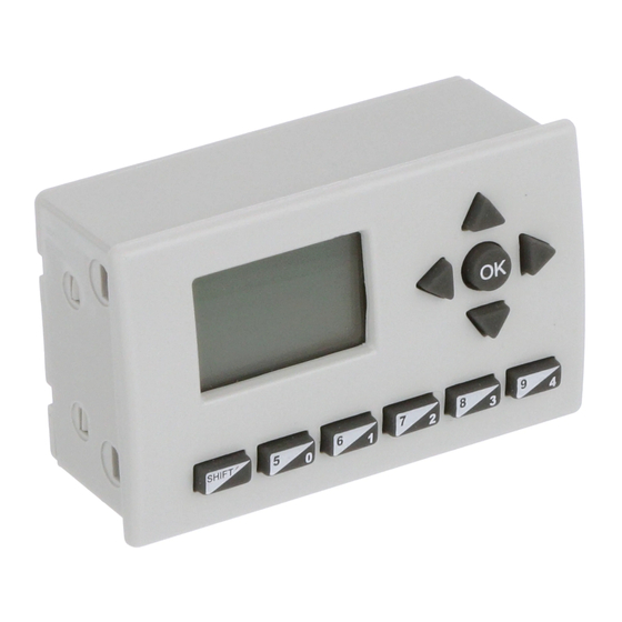
Page 12: Operator Panel
Shift key: This works in conjunction with the data entry keys to obtain values 5 through 9. Press and hold the Shift key while pressing a 0 to 4 key enters the comparable 5 to 9 value. PHOENIX CONTACT 2338_en_O... -
Page 13: Nlc-Op2-Lcd-076-4X20
The Operator Panel is hot-swappable and doesn’t require rebooting the controller. The NLC-OP2-LCD-076-4X20 is not powered from the NLC... and requires a separate, 12 or 24 V DC power source. Additional information on the Operator Panels is provided in Section 5, “Operator Panel usage”. 2338_en_O PHOENIX CONTACT... -
Page 14: Nanonavigator Programming Software
PC using a Windows 2000 or newer, 32- or 64-bit operating system. nanoNavigator software is available for download at phoenixcontact.com. For more information on using the nanoNavigator software, refer to the nanoNavigator User Manual. PHOENIX CONTACT 2338_en_O... -
Page 15: Installation And Connection Of Nanoline Components
NOTE: Do not remove the plastic cover when not installing an expansion module. – Remove the left-side plastic to connect a communication expansion module. – Remove the right-side plastic to connect I/O expansion modules. 2338_en_O PHOENIX CONTACT... -
Page 16: Base Unit Release Latch
Release latch Figure 2-2 Base unit release latch Hook the unit onto the mounting rail. Swivel the module fully onto the rail and push the release latch in to secure it to the rail. Figure 2-3 Rail placement PHOENIX CONTACT 2338_en_O... -
Page 17: Removing Modules From The Mounting Rail
If expansion modules are installed, slide them away, one at a time, from the base unit. Slide communication expansion modules to the left and I/O expansion modules to the right. NOTE: Do not slide multiple I/O expansion modules as a group as damage to the interfacing connectors may occur. 2338_en_O PHOENIX CONTACT... -
Page 18: Option Modules
(rotated), may cause damage to either the option module or base unit or both. Do not force option modules into a slot. They will slide easily when properly aligned. Install the Operator Panel and any option modules in the base unit before mounting the unit. PHOENIX CONTACT 2338_en_O... -
Page 19: Base Unit Slots
– the module is oriented properly – text must be oriented the same as other text on the face of the base unit. – the tabs are properly seated to secure the module in the base unit. 2338_en_O PHOENIX CONTACT... -
Page 20: Connections
The other end is open for connection to whatever type of connector is required. Trim the cable to the desired length before connecting. The NLC-MOD-RS485 option module supports connection of up to 16 nodes before a repeater is required. PHOENIX CONTACT 2338_en_O... -
Page 21: Modbus Network Connection (Nlc-03
The NLC-035… is capable of two-wire RS-485 connection for Modbus communication. A six-pin RJ12 connector attaches to the bottom of the controller, opposite the power connections. Pin 1 RJ12 open black Figure 2-8 RJ-12 to open end for 2-wire RS-485 connection 2338_en_O PHOENIX CONTACT... -
Page 22: Usb Connections
Panel installed in the base unit. Do not force option modules into a slot. They will slide easily when properly aligned. Install the Operator Panel and any option modules in the base unit before mounting the unit. PHOENIX CONTACT 2338_en_O... -
Page 23: Local Installation
Panel. The Receptor Panel snaps into the base unit housing and is powered through the connector in the base unit just like the Operator Panel. NOTE: Orient the Receptor Panel so the connector on the back mates with the connector in the base unit slot. 2338_en_O PHOENIX CONTACT... -
Page 24: Receptor Panel, Display Cable And Remote Operator Panel
When mounted remotely, the Operator Panel must be within 0.6 m of the base unit for proper communication. NOTE: To ensure proper power supply and communication with the Operator Panel, only use a display cable supplied by Phoenix Contact. NLC-OP1-LCD-032-4X20 Operator Panel... -
Page 25: Cutout Dimensions For Panel Mounting
Do not drill holes for the mounting screws; they do not pass through the enclosure wall. Insert the Operator Panel into the hole from the front. Mounting bracket Mounting screw IF T Operator Gasket Panel Enclosure wall Display cable Figure 2-13 Remote Operator Panel installation 2338_en_O PHOENIX CONTACT... - Page 26 8-pin RJ45 connector attaches to the Receptor Panel. For NLC-03… base units, an 6-pin RJ12 connector attaches directly to the base unit. A D-SUB 9 male connector attaches to the Operator Panel. Figure 2-14 RJ12 to D-SUB 9 cable PHOENIX CONTACT 2338_en_O...
- Page 27 Communication between the base unit and Operator Panel is via RS-232. This standard has a maximum length of 15 m. To mount the Operator Panel in an enclosure or cabinet: Base unit Operator Panel Display cable Figure 2-16 Remote Operator Panel installation 2338_en_O PHOENIX CONTACT...
-
Page 28: Connecting Power, Inputs And Outputs
Use a small screwdriver to turn the screw counterclockwise to release and clockwise to tighten wires after insertion into the appropriate position. CAUTION: Do not apply power to the Nanoline controller until directed to do so in the commissioning (startup) procedure. PHOENIX CONTACT 2338_en_O... -
Page 29: Power
Power always connects to the base unit that powers any installed modules. Inputs and outputs are optically isolated from the power input to the base unit. nanoLine nanoLine – NLC-EMC-PWR-01 Order No. 2701070 NLC-050-100A-08I-04QRA-05A Order No. 2701069 Figure 2-18 Power connections 2338_en_O PHOENIX CONTACT... -
Page 30: Digital Inputs
PNP-type input connection (base unit shown) – Figure 2-21 NPN-type input connection (base unit shown) Terminals are labeled as COM, shared by all channels, or Ix where x indicates the channel number. Channel numbering starts with 0. PHOENIX CONTACT 2338_en_O... -
Page 31: Digital Outputs
0. Positive (+) and negative (–) terminals are common for all channels. QO Q1 Q2 Q3 – Figure 2-22 Digital NPN output connection (base unit shown) QO Q1 Q2 Q3 – Figure 2-23 Digital PNP output connection (base unit shown) 2338_en_O PHOENIX CONTACT... -
Page 32: Analog Inputs
Each output channel has a current or voltage signal. Terminals are labeled as COM, shared by all channels, Ix where I indicates current output or Ux where U indicates a voltage output. The x indicates a channel number. Channel numbering starts with 0. PHOENIX CONTACT 2338_en_O... -
Page 33: Relay Outputs
To prevent such arcs from occurring, the contacts/loads must be fitted with protective circuits. In general, the following protective circuits can be used: – contact protective circuit – load protective circuit – combination of both protective circuits Figure 2-27 Contact protective circuit (A), load protective circuit (B) 2338_en_O PHOENIX CONTACT... - Page 34 Yes (U Advantages: diode short Non-critical sizing Disadvantages: Load Attenuation only above U Suppressor diode Medium to Yes (U Advantages: short Cost-effective Non-critical sizing Load Limits positive peaks Suitable for AC voltage Disadvantages: Attenuation only above U PHOENIX CONTACT 2338_en_O...
- Page 35 HF attenuation via power store Level-independent attenuation Reactive-current compensation Load Disadvantages: Exact sizing required Only suitable for DC voltage Capacitor sizing: C = L / 4 x R Load Load² Resistor sizing: R = 0.2 x R Load 2338_en_O PHOENIX CONTACT...
-
Page 36: Temperature Inputs
Figure 2-28 PT100/PT1000 connection A1 B1 C1 Figure 2-29 Thermocouple connection Each input channel has signal (Ax), sense (Bx) and return (Cx) terminals, where x indicates the channel number. A common ground is available to attach the shield. PHOENIX CONTACT 2338_en_O... -
Page 37: Led Indicators
Valid project present and running with no faults or warn- ings Valid project present and stopped, or no power present 1/3-second flash Fault exists and project stopped 1-second flash Valid project present and running but with warnings Power is present No power is present 2338_en_O PHOENIX CONTACT... - Page 38 Nanoline PHOENIX CONTACT 2338_en_O...
-
Page 39: Communication
The memory module can be removed from the base unit. When using the RS-232 or RS-485 module, the controller can exchange data using the Modbus RTU protocol. 2338_en_O PHOENIX CONTACT... -
Page 40: Serial Communication With Pc (Nlc-Pc/Serial-Cbl 1M Cable Shown)
Double-click the desired port (COM1) to open the “Communications Port” dialog box. Click the “Port Settings” tab. Set the various fields as follows: Bits per second 9600 Data bits Parity none Stop bits Flow control none Click the “OK” button when finished. PHOENIX CONTACT 2338_en_O... -
Page 41: Usb
– upload a project from a memory module to nanoNavigator. – download a project from a memory module to a Nanoline controller. – upload a project from a Nanoline controller to a memory module. 2338_en_O PHOENIX CONTACT... - Page 42 The memory module performs different operations depending upon where it is installed and the configuration of the Nanoline, and whether there is a project stored in memory. Table 3-1 indicates what action happens when a Nanoline system has power applied while a memory module is installed. PHOENIX CONTACT 2338_en_O...
-
Page 43: Ethernet Communication
Ethernet connection is through an RJ45 port on the front of the module. nanoLine Controller Ethernet Modbus TCP LNK/ACT Module Network Figure 3-2 NLC-COM-ENET-MB1 communication expansion module The NLC-COM-ENET-MB1 and NLC-050-100A-08I-04QRA-05A cannot be used together and still meet CE compliance. 2338_en_O PHOENIX CONTACT... -
Page 44: Leds
Nanoline is capable of communicating on the Verizon wireless CDMA network. The NLC-COM-CELLULAR-CDMA module is certified for use on a Verizon network. For information on configuration of the NLC-COM-GSM and NLC-COM-CELLULAR- CDMA modules, see the UM EN NLC-COM-GSM (2759). PHOENIX CONTACT 2338_en_O... -
Page 45: Modbus Communication
ModScan32 is a software application that operates as a Modbus master. It provides the ability to change data points in a connected slave device using either the RTU or ASCII Transmission mode. The following provides a few common procedures that can be accomplished using ModScan32. 2338_en_O PHOENIX CONTACT... -
Page 46: Connection Details" Dialog Box With Remote Modbus Parameters
Address was obtained using DHCP, use Wireshark or an equivalent IP sniffer to determine the IP Address assigned. Enter 502 in the “Service Port” field (the default is 502). Click the “Protocol Selections” button and enter “1 ms” in the “Delay Between Polls” field. Click the “OK” button. PHOENIX CONTACT 2338_en_O... -
Page 47: Connection Details" Dialog Box With Direct Connection Parameters
Click the “OK” button. ModScan32 running Modbus Holding Registers are shown in the status window. Use the Modbus Holding ® Registers chart (see “Modbus holding registers” on page 83) to determine the value and meaning of these registers. 2338_en_O PHOENIX CONTACT... - Page 48 Figure 3-8 “Write Coil” dialog box The “Write Coil” dialog box allows changing the status of the coil or flag. When the project is running, the coil or flag may change, depending on the flow chart logic. PHOENIX CONTACT 2338_en_O...
-
Page 49: Nanoline To Nanoline Communication
Connection between the two Nanoline controllers is through either an RS-232 or RS-485 crossover cable. The controller must be equipped with the appropriate communication module (NLC-MOD-RS232 or NLC-MOD-RS485) to allow connection of the cable. Pin 1 Pin 1 RJ11 RJ11 Figure 3-9 RS-232 cable 2338_en_O PHOENIX CONTACT... -
Page 50: Configuration
In the “Base Unit” group click the “Configure” button. In the resulting dialog box, choose the appropriate NLC-MOD-RS232 or NLC-MOD-RS485 option module. Click the “Configure” button in the “Communication Option Module” group. Click the “Enable Master” check box in the “Configure Serial Port” dialog box (see Figure 3-11). PHOENIX CONTACT 2338_en_O... -
Page 51: Real-Time Clock
This information can be set for a project when not connected to a base unit by clicking the “nanoLC… Configuration…” menu and clicking the “Configuration” button for the base unit. From the “Configure Base Unit” dialog box, select the nLC-MOD-RTC option module in Slot #2 and click the “Configure” button. 2338_en_O PHOENIX CONTACT... - Page 52 If European is selected, the “EU Time Zone” drop-down box allows selection of the closest time zone from Greenwich Mean Time (GMT) up to 2 hrs. – Set the “Fault” drop-down list to either Fault or Warning. PHOENIX CONTACT 2338_en_O...
-
Page 53: Rtc Faults
If the battery fails while running, the controller continues to function as long as power is applied. The Error Message appears at the top of the hour. The Flags related to Error Messages can be read by a Modbus client/master. They can also be read by the program using a Decision block. 2338_en_O PHOENIX CONTACT... - Page 54 Nanoline PHOENIX CONTACT 2338_en_O...
-
Page 55: Commissioning
– Specialist field equipment details – Control strategy details/drawings – Configuration program – Health and safety assessment Initial briefing by the Contracts Engineer, Applications Engineer and Electrical Supervisors are essential for a smooth transition through the project. 2338_en_O PHOENIX CONTACT... -
Page 56: Installation Checks
It should be separated from wiring of substantially different voltages, i.e., 115 or 230 V AC should be separated from high voltage wiring of 440 volts and up, and low voltage of 50 volts and less. PHOENIX CONTACT 2338_en_O... -
Page 57: Field Wiring Checks
Shielded cables are grounded/earthed to the ground/earth terminal strip provided on the Nanoline. – Wiring is tagged and labeled. – Wiring is neat and tidy. – Wiring is installed as described in the point chart. – Internal power wiring is connected correctly and to the right polarity. 2338_en_O PHOENIX CONTACT... - Page 58 Select any return and any field supply terminal and test for a short circuit. Should a short circuit be present, all the terminals will need to be disconnected and re-tested individually because both the return and field supplies may be common elsewhere. Return and input/output terminals PHOENIX CONTACT 2338_en_O...
-
Page 59: Power Up And Functionality Checks
Review and correct any conditions found until the LED operates correctly. 4.1.3.2 Operator Panel Once the power is applied, the optional Operator Panel should illuminate. If a program is loaded, a programmed startup screen will appear. If a program is not loaded, a status page will appear. 2338_en_O PHOENIX CONTACT... -
Page 60: Field Equipment Commissioning
47 for additional information. 4.1.4.3 Addressing the inputs Ensure the Nanoline is stopped. From the Operator Panel: • Press the <Shift> and <OK> keys on the Operator Panel. • Press the <1> key to stop processing. Or from nanoNavigator: PHOENIX CONTACT 2338_en_O... -
Page 61: Nanonavigator 2 "Nanoline Configuration" Dialog Box Showing Configuration Of Nlc-050
(see Figure 4-2). • Click the “Nanoline… Configuration” menu to open the “nanoLC Configuration” dialog box. Figure 4-1 nanoNavigator 2 “Nanoline Configuration” dialog box showing configuration of NLC-050… system 2338_en_O PHOENIX CONTACT... -
Page 62: Nanonavigator 3 "Nanoline Configuration" Dialog Box Showing Configuration Of Nlc-055
(see Figure 4-2). • Click the “nanoLC… Configuration” menu to open the “nanoLC Configuration” dialog box. • Ensure correct selection of the base unit and I/O expansion modules in each drop-down menu. PHOENIX CONTACT 2338_en_O... - Page 63 The speed with which this stage can be achieved depends upon the accuracy of the end- to-end checks performed during the installation checks. The field equipment cannot be checked and calibrated properly unless it is installed in the proper location and any commissioning required by the sensor/actuator has taken place. 2338_en_O PHOENIX CONTACT...
-
Page 64: Analog Inputs
Cable routing must be kept separate from any AC power wiring. The route of the cable should be verified against the network layout drawing and all input and output destinations tagged on the cables at each node. PHOENIX CONTACT 2338_en_O... -
Page 65: Modbus Communication
– When using BootP IP Addressing, use the IPAssign program available from Phoenix Contact as a free BootP server IP assignment tool. The IP address will be assigned after a download is performed to the Nanoline and IPAssign is run. - Page 66 Nanoline PHOENIX CONTACT 2338_en_O...
-
Page 67: Operator Panel Usage
Numbers 5 through 9 can be entered by holding the <Shift> key and pressing the desired number. When used within a Decision block, pressing a key, either <OK>, an arrow, or number key, is considered a digital ON. 2338_en_O PHOENIX CONTACT... -
Page 68: Special Key Combinations
Not all screens display “SF ” at the bottom of the screen. However, pressing the <Shift> and keys always displays the previous menu, even when not displayed at the bottom. key SHIFT <Shift> key <Shift> and keys Figure 5-2 PHOENIX CONTACT 2338_en_O... -
Page 69: Key Usage For Nlc-Op2-Lcd-076-4X20
When in Run mode, press the Menu and <1> keys together to adjust the color of the screen. Press the 1, 2, or 3 key to select the corresponding background color. Press the <OK> key to save the settings. Press the <Menu back> key to cancel the changes. Figure 5-4 Background color 2338_en_O PHOENIX CONTACT... - Page 70 or keys to select from the available menu choices. Figure 5-6 Serial port settings The factory default settings are: Baud rate 115200 Parity Stop Bits Press the <OK> key to save the settings. Press the <Menu back> key to cancel the changes. PHOENIX CONTACT 2338_en_O...
-
Page 71: Run Mode
The I/O indicators show the I/O that is available within the Nanoline and the expansion modules. If there was one expansion module attached, the display would look like Figure 5-9. Figure 5-9 Project running, no display, and one expansion module 2338_en_O PHOENIX CONTACT... -
Page 72: No Project Loaded
The third possible initial display screen is no project loaded onto the Nanoline. Upon power- up, the screen will look like Figure 5-12. Figure 5-12 Project not running, no display Figure 5-12 shows a Nanoline base unit only on the left and a Nanoline with three expansion modules on the right. PHOENIX CONTACT 2338_en_O... -
Page 73: Monitor Mode
The password, project name and setup information are entered in nanoNavigator by the programmer. The status for each item is displayed in reverse text (light on dark) next to the associated item. 2338_en_O PHOENIX CONTACT... -
Page 74: System Menu
The first column shows the physical location of the input channel. For example, Figure 5-16 shows inputs I0 through I5 are in the Nanoline base (CPU), and inputs I06 and I07 are on the first expansion module (E1--). PHOENIX CONTACT 2338_en_O... -
Page 75: Figure 5-17 Force Input Options
The “r” indication means the output is retentive (saved when power to the Nanoline is removed). – The “f” indication means the output is forced to a state of ON or OFF. – The third column indicates the current status of the output (OFF or ON). 2338_en_O PHOENIX CONTACT... -
Page 76: Figure 5-19 Force Output Options
Set as Retentive – When an output is set as retentive, it stores the current state in memory in the event of a power failure. When power is restored, the stored state is recalled and the output placed in that state. PHOENIX CONTACT 2338_en_O... -
Page 77: Figure 5-21 Setting An Output As Retentive
The “r” indication means the flag is retentive (saved when power to the Nanoline is removed). – The “f” indication means the flag is forced to a state of ON or OFF. – The third column indicates the current status of the flag (OFF or ON). 2338_en_O PHOENIX CONTACT... -
Page 78: Figure 5-24 Force Flag Options
To set the flag as non-retentive, from the flag list screen, use the or key to highlight the desired flag. Press the <OK> key, and then press the <4> key to set the flag as non- retentive. Figure 5-26 Removing the retentive setting PHOENIX CONTACT 2338_en_O... -
Page 79: Figure 5-27 Timer/Counter List
Use the or key to highlight the desired timer/counter, and then press the <OK> key. Figure 5-29 Entering a timer/counter preset value The format of the timer/counter value defaults to the value previously selected in nanoNavigator. The format possibilities are: Counter xxxxxx HH:MM:SS xx:xx:xx Seconds x.xxx 2338_en_O PHOENIX CONTACT... -
Page 80: Figure 5-30 Setting A Timer/Counter As Retentive
The first column displays the number of the register number. – The “r” indication means the register is retentive (saved when power to the Nanoline is removed). – The second column indicates the current value stored in the register. PHOENIX CONTACT 2338_en_O... -
Page 81: Figure 5-33 Entering A Register Value
To set the register as non-retentive, from the register list screen, use the or key to highlight the desired register. Press the <OK> key, and then press the <4> key to set the register as non-retentive. Figure 5-35 Removing the retentive setting 2338_en_O PHOENIX CONTACT... -
Page 82: Run/Stop Menu
Execution begins immediately. Unlike stopping execution, no additional screens are provided. Select Status 0 Monitor 1 Run/Stop - Stopped Password - Not Set Proj - Sprinkler Sy 4 Setup - PN 2701027 Figure 5-37 Press 1 to start program execution PHOENIX CONTACT 2338_en_O... -
Page 83: Password
The project name can have up to 256 characters but only the first 12 characters are displayed on the Operator Panel. Figure 5-39 Project name The Nanoline stores one project at a time. For information on downloading and uploading projects, refer to “Communication” on page 35. 2338_en_O PHOENIX CONTACT... -
Page 84: Setup
The fourth line is a header for I/O expansion modules installed. Beginning on the fifth line are the type and quantity of digital channels on each I/O expansion module. A line only appears when a module is connected. PHOENIX CONTACT 2338_en_O... -
Page 85: Memory Module
5. If not present, line 5 is not displayed. If a memory option module is present, from the System menu press the <5> key to access MemMod menu.The MemMod menu allows the user to: 2338_en_O PHOENIX CONTACT... -
Page 86: Memory Module Menu With Project Running
If the project is running, option 1 is not available until the project is stopped. Figure 5-47 Memory Module menu with project stopped For more information on how the optional memory module works, refer to “Memory Module” on page 37. PHOENIX CONTACT 2338_en_O... -
Page 87: A Technical Appendix
ON = Reset to factory default OFF = Continue with current settings – UCS: Update Configuration and Settings ON = Update and apply the new configuration and settings from base module OFF = Continue with the current settings 2338_en_O PHOENIX CONTACT... - Page 88 IP-CONFLICT: This is valid only when default address is applied to the unit. ON = IP Address applied to the communication expansion module is duplicated on the network (expansion module will not work correctly) OFF = IP Address applied to the communication expansion module is unique in the network PHOENIX CONTACT 2338_en_O...
- Page 89 Holding register 0x0106: Subnet mask 2 (ModScan32 address: 40262) Subnet mask 3 Subnet mask 4 Holding register 0x0107: Default gateway 1 (ModScan32 address: 40263) Default Gateway 1 Default Gateway 2 Holding register 0x0108: Default gateway 2 (ModScan32 address: 40264) Default Gateway 3 Default Gateway 4 2338_en_O PHOENIX CONTACT...
-
Page 90: A 2 Modbus/Nanoline Communication
0 so all decimal ranges shown are offset by a factor of one, i.e. hexadecimal 0x1000 is the equivalent of decimal 4096, but because of ModScan32 addressing, the starting address is actually 4097. If using ModScan32 in the hexadecimal format, then hexadecimal 0x1000 actually equals 0x1001. PHOENIX CONTACT 2338_en_O... -
Page 91: A 2.1 Nlc-050
Modbus Request Address 0x2000 and the high-order 16-bits of Nanoline Timer/Counter Preset 0 would occupy Modbus Request Address 0x2001. Nanoline Timer/Counter Preset 1 would occupy Modbus Request Addresses 0x2002 and 0x2003) † Multiple Modbus commands may be required to view the entire Modbus range. 2338_en_O PHOENIX CONTACT... -
Page 92: A 2.2 Nlc-055
Modbus Request Address 0x2000 and the high-order 16-bits of Nanoline Timer/Counter Preset 0 would occupy Modbus Request Address 0x2001. Nanoline Timer/Counter Preset 1 would occupy Modbus Request Addresses 0x2002 and 0x2003) † Multiple Modbus commands may be required to view the entire Modbus range. PHOENIX CONTACT 2338_en_O... -
Page 93: A 3 Special Formats
Calculator or equivalent. Each pair of hex digits are individually converted to decimal format. 726583 Decimal value Hex value 0 0 0 B 1 6 3 7 Formatted value 11:22:55 Figure A-3 Time-formatted data item type conversion using hex format 2338_en_O PHOENIX CONTACT... - Page 94 Nanoline PHOENIX CONTACT 2338_en_O...
-
Page 95: B Technical Appendix - Status/Command Flags
Some commands are specific to the Nanoline and others allow control from a remote device via the Ethernet connection. – Ethernet flags represent the bits of Modbus Holding Registers 0x0101 (Command register) and 0x0102 (Status register). – Flags 72-87 are commands (see Table B-2) and may be turned on or off. 2338_en_O PHOENIX CONTACT... - Page 96 Reserved for future use F-84 ETH Command 12 (Reserved) Reserved for future use F-85 ETH Command 13 (Reserved) Reserved for future use F-86 ETH Command 14 (Reserved) Reserved for future use F-87 ETH Command 15 (Reserved) Reserved for future use PHOENIX CONTACT 2338_en_O...
-
Page 97: Ethernet Status Flags
Reserved for future use F-100 ETH Status 12 (Reserved) Reserved for future use F-101 ETH Status 13 (Reserved) Reserved for future use F-102 ETH Status 14 (Reserved) Reserved for future use F-103 ETH Status 15 (Reserved) Reserved for future use 2338_en_O PHOENIX CONTACT... -
Page 98: B 2 Nlc-055
Flags 152-167 are status flags (see Table B-6) and are read only. If the NLC-COM-GSM or NLC-COM-CELLULAR-CDMA module is installed, some flags may be used for other purposes. Refer to the NLC-COM-GSM user manual for GSM flags. PHOENIX CONTACT 2338_en_O... - Page 99 ETH Command 11 Reserved for future use F-148 ETH Command 12 Reserved for future use F-149 ETH Command 13 Reserved for future use F-150 ETH Command 14 Reserved for future use F-151 ETH Command 15 Reserved for future use 2338_en_O PHOENIX CONTACT...
-
Page 100: Ethernet Status Flags
ETH Status 11 Reserved for future use F-164 ETH Status 12 Reserved for future use F-165 ETH Status 13 Reserved for future use F-166 ETH Status 14 Reserved for future use F-167 ETH Status 15 Reserved for future use PHOENIX CONTACT 2338_en_O... -
Page 101: C Technical Appendix - Commissioning
Component Name Hot-swappable RS-232 option module NLC-MOD-RS232 RS-485 option module NLC-MOD-RS485 USB option module NLC-MOD-USB Memory module NLC-MOD-MEM 032K Real-time cock NLC-MOD-RTC Operator Panel NLC-OP1-LCD-032-4X20 Ethernet module NLC-COM-ENET-MB1 GSM module NLC-COM-GSM CDMA module NLC-COM-CELLULAR-CDMA I/O expansion modules 2338_en_O PHOENIX CONTACT... -
Page 102: C 2 Commissioning Checklist
Check for AC voltages Use meter Check for DC voltages Use meter Check for short circuits to earth ground Use meter Check for short circuits between terminals Use meter * Suggested status codes; X - Completed; NA - Not applicable PHOENIX CONTACT 2338_en_O... - Page 103 Check programmed control logic manually Ethernet installation checks Check Ethernet operations Ethernet wiring and hardware checks Check Ethernet wiring Ethernet data transmission Check communications using Modscan32 software * Suggested status codes; X - Completed; NA - Not applicable 2338_en_O PHOENIX CONTACT...
-
Page 104: C 3 Points Chart
Table C-4 Output points list Module Hardware Software Type Label Comments Base Q-00 Base Q-01 Base Q-02 Base Q-03 Q-04 Q-05 Q-06 Q-07 Q-08 Q-09 Q-10 Q-11 Q-12 Q-13 Q-14 Q-15 PHOENIX CONTACT 2338_en_O... - Page 105 Input points list Module Hardware Software Type Label Comments Base I-00 Base I-01 Base I-02 Base I-03 Base I-04 Base I-05 I-06 I-07 I-08 I-09 I-10 I-11 I-12 I-13 I-14 I-15 I-16 I-17 I-18 I-19 I-20 I-21 I-22 I-23 2338_en_O PHOENIX CONTACT...
- Page 106 Nanoline Table C-6 Analog points list Module Hardware Software Type Label Comments AQ-00 AQ-01 AQ-02 AQ-03 AQ-04 AQ-05 AQ-06 AQ-07 AQ-08 AI-01 AI-02 AI-03 AI-04 AI-05 AI-06 AI-07 AI-08 PHOENIX CONTACT 2338_en_O...
-
Page 107: D Technical Appendix - Technical Data
Operator Panel cable, RJ45 to RJ45, 60 cm, for remote display NLC-OP1-MKT-CBL 2701438 Operator Panel cable, RJ45 to DSUB 9, 290 cm, for NLC-OP2-LCD-076- NLC-OP2-RJ45-CBL 2400195 4X20 and NLC-OP1-MKT Operator Panel cable, RJ12 to DSUB 9, 290 cm, for NLC-OP2-LCD-076- NLC-OP2-RJ11-CBL 2400196 4X20 and NLC-035-024D-04I-02QRD-05A 2338_en_O PHOENIX CONTACT... -
Page 108: Nanonavigator
Serial cable, RJ11 to open, 5 m NLC-RS485-CBL 5M 2701073 Serial cable, USB to RJ11, 2 m NLC-USB to SERIAL-CBL 2M 2400111 Real-time clock module, provides time storage in off-power situations NLC-MOD-RTC 2701153 nanoNavigator configuration software NLC-NAV-01 2701221 PHOENIX CONTACT 2338_en_O... -
Page 109: D 2 Technical Specifications
19…30 V DC 100… 19…26 V AC 240 V AC Typical current consumption 92 mA 150 mA 150 mA 70 mA @ 24 DC @ 230 V AC Maximum current consumption 250 mA – Protection Reverse polarity 2338_en_O PHOENIX CONTACT... -
Page 110: Digital Outputs
– 100,000 cycles Operating frequency No load 100 Hz 300 operations per minute Rated load 100 Hz 30 operations per minute Overload response Restart after removal of External protection required. overload Protection Thermal fuse External protection required. PHOENIX CONTACT 2338_en_O... -
Page 111: D 2.2 Nlc-055
100… 240 V AC Typical current consumption 100 mA 150 mA 250 mA 50 mA @ 230 V AC Maximum current consumption 250 mA 250 mA 400 mA 70 mA @ 110 V AC Protection Reverse polarity 2338_en_O PHOENIX CONTACT... - Page 112 1.5 @ 120 V AC / 0.9 @ 240 V AC Signal delay @ 20°C (excluding bounce) – 10 ms Release time @ 20°C (excluding bounce) – 4 ms Mechanical service life – 10 x 10 cycles Electrical service life (see Figure D-1) – 100,000 cycles PHOENIX CONTACT 2338_en_O...
-
Page 113: Nlc-035
Screw terminal, 0.2 - 2.5 mm², 12-24 AWG, 0.5-0.6 Nm Operating temperature range -25…70°C Storage temperature range -25…85°C Humidity (maximum) @ 25°C System data 2702031 2400079 Number of expansion modules Number of communication expansion modules Number of base unit option modules 2338_en_O PHOENIX CONTACT... - Page 114 Nominal load 7.2 W (80 Ohmic Lamp 7.2 W 7.2 VA (1.2 H, 80 Inductive Operating frequency No load 100 Hz Rated load 100 Hz Overload response Restart after removal of overload Protection External protection required PHOENIX CONTACT 2338_en_O...
-
Page 115: D 2.4 Digital I/O Expansion Module
Nominal input current OFF 1 mA 0.2 mA Response time ON 60 µs 600 µs 850 µs Response time OFF 70 µs 700 µs 960 µs Protection Polarity reversal – Permissible cable length to sensor 100 m 2338_en_O PHOENIX CONTACT... - Page 116 – 100,000 cycles Operating frequency No load 100 Hz 300 operations per minute 100 Hz 30 operations per minute Rated load Overload response Restart after removal of overload Requires external protection Protection Thermal fuse Requires external protection PHOENIX CONTACT 2338_en_O...
-
Page 117: Analog Expansion Module (Order No. 2701098)
12 bit Basic error limit 1.00% Cut-off frequency (3 dB) 5 Hz Current input Signal input 0…20 mA / 4…20 mA 120 Input resistance of current input Basic error limit 1.00% Cut-off frequency (3 dB) 5 Hz 2338_en_O PHOENIX CONTACT... -
Page 118: Analog Expansion Module (Order No. 2701040)
0…10 V DC 1000 Input resistance of voltage input Resolution 12 bit Basic error limit 1.00% Current output Signal output 0…20 mA / 4…20 mA 500 Input resistance of current input Basic error limit 1.00% PHOENIX CONTACT 2338_en_O... -
Page 119: D 2.7 Temperature Expansion Module (Order No. 2701671)
±1% full scale +1°C (CJC error) -100°C 1300°C ±1% full scale +1°C (CJC error) -50°C 1769°C ±1.5% full scale +1°C (CJC error) -50°C 1769°C ±1.5% full scale +1°C (CJC error) -100°C 400°C ±1.5% full scale +1°C (CJC error) 2338_en_O PHOENIX CONTACT... -
Page 120: Operator Panel (Order No. 2701137)
-0…60°C Humidity (maximum) @ 50°C Supply voltages Typical current consumption 32 mA Maximum current consumption 50 mA Connection Supplied by base via connector Interface Communication method Serial link Connector type 2.54 mm socket or custom RJ45 cable PHOENIX CONTACT 2338_en_O... -
Page 121: Operator Panel (Order No. 2701945)
103 x 40 x 43 mm Weight 88 g Degree of protection IP20 Operating temperature range -25…60°C Storage temperature range -25…85°C Humidity (maximum) @ 25°C Interface Communication method Modbus Ethernet Communication rate 10/100 Mbps Number of simultaneous connections Connection method RJ45 2338_en_O PHOENIX CONTACT... -
Page 122: Gsm Modem Module (Order No. 2701344)
Power output 850, 900 MHz 1800, 1900 MHz Interface SIM Card 6 pin, 3 V Communication method Antenna connection SMA-F Antenna requirements Power >2 W Gain <3 dBi 50 Impedance Recommended VSWR <2:1 Required VSWR <10:1 PHOENIX CONTACT 2338_en_O... -
Page 123: Cdma Modem Module (Order No. 2400428)
Frequency 800/1900 MHz CDMA 1x RTT/1x EV-DO Rev. A Power output 0.25 W Interface Communication method CDMA Antenna connection SMA-F Antenna requirements Power >0.25 W Gain <5.12 dBi 50 Impedance Recommended VSWR <2:1 Required VSWR <5:1 2338_en_O PHOENIX CONTACT... -
Page 124: Base Unit Option Module
Communication rate 115 kbps 12 Mbps Connection method Slot #1 Connector type RJ12 Recommended cable (Phoenix Contact Order No.) 2701234 2701073 2701247 D 2.14 RTC technical specifications (Order No. 2701153) General Dimensions (H x W x D) 24.5 x 25.5 x 49 mm... -
Page 125: Conformance/Approvals
0.5 kV symmetrical Conducted Interference IEC/EN 61000-4-6 Criterian A Test voltage 10 V Noise emissions according to 61000-6-4 EN 55011 Class A Industrial 1000000 100000 10000 Current (A) Figure D-1 Relay life expectancy @ 120 V AC 2338_en_O PHOENIX CONTACT... - Page 126 Nanoline PHOENIX CONTACT 2338_en_O...
-
Page 127: Appendixes
NPN-type input connection (base unit shown) ........26 Figure 2-22: Digital NPN output connection (base unit shown) ....... 27 Figure 2-23: Digital PNP output connection (base unit shown) ....... 27 Figure 2-24: Analog input connection ..............28 2338_en_O PHOENIX CONTACT... - Page 128 Serial port settings ................66 Figure 5-7: Opening screen in Run mode ............. 67 Figure 5-8: Project running, no display, and no expansion modules ..... 67 Figure 5-9: Project running, no display, and one expansion module ..... 67 PHOENIX CONTACT 2338_en_O...
- Page 129 Password Not Set ................79 Figure 5-39: Project name ..................79 Figure 5-40: Setup menu ..................80 Figure 5-41: Setup screen ..................80 Figure 5-42: System information screen ..............80 Figure 5-43: Set Date screen .................. 81 2338_en_O PHOENIX CONTACT...
- Page 130 Time-formatted data item type using binary format ......89 Figure A-2: Date-formatted data item type using binary format ......89 Figure A-3: Time-formatted data item type conversion using hex format ....89 Appendix D Figure D-1: Relay life expectancy @ 120 V AC ............ 121 PHOENIX CONTACT 2338_en_O...
-
Page 131: E 2 List Of Tables
Base unit status flags................91 Table B-2: Ethernet command flags..............92 Table B-3: Ethernet status flags ................93 Table B-4: Base unit status flags................94 Table B-5: Ethernet command Flags..............95 Table B-6: Ethernet status flags ................96 2338_en_O PHOENIX CONTACT... - Page 132 Hot-swappable components..............97 Table C-2: Suggested pre-commissioning checklist ..........98 Table C-3: Power up and functionality checklist ............ 99 Table C-4: Output points list ................100 Table C-5: Input points list................... 101 Table C-6: Analog points list ................102 PHOENIX CONTACT 2338_en_O...
-
Page 133: E 3 Index
Installing modules ............11 Analog inputs............28 Analog outputs ............28 Digital inputs............26 LEDs Digital outputs............27 Base unit ..............33 Power ..............25 Ethernet module ............. 40 Relay outputs ............29 RS-232 ..............36 RS-485 ..............37 Serial ..............35 Temperature inputs ..........32 USB................37 2338_en_O PHOENIX CONTACT... - Page 134 Analog ..............28 Start-up behavior ............38 Connection .............24 Digital ..............27 Relay ..............29 Temperature inputs............32 Troubleshooting ............69 Ethernet..............40 Opening message screen ........ 67, 68 Type codes Base unit ..............6 Expansion module............ 7 USB ................37 PHOENIX CONTACT 2338_en_O...
Need help?
Do you have a question about the Nanoline Series and is the answer not in the manual?
Questions and answers