Xerox Phaser 6128MFP Service Manual
Hide thumbs
Also See for Phaser 6128MFP:
- User manual (182 pages) ,
- Quick use manual (17 pages) ,
- Quick user manual (16 pages)
Table of Contents
Advertisement
Quick Links
Advertisement
Table of Contents
Troubleshooting

Related Manuals for Xerox Phaser 6128MFP


Summary of Contents for Xerox Phaser 6128MFP
- Page 1 Phaser 6128MFP ® Multi-Function Printer Phaser 6128MFP ® Service Manual...
- Page 3 Phaser 6128MFP ® Service Manual Warning The following servicing instructions are for use by qualified service personnel only. To avoid personal injury, do not perform any servicing other than that contained in the operating instructions, unless you are qualified to do so. First Printing: March 2009...
- Page 4 Xerox technical training materials and service manuals are intended for use by authorized Xerox service technicians and service partners only and are not for resale. These materials may not be distributed, copied, or otherwise reproduced without prior written consent from Xerox Corporation.
-
Page 5: Table Of Contents
Information Pages................1-27 Phaser 6128MFP Service Manual... - Page 6 Phaser 6128MFP Operational Overview ........
- Page 7 Non-Xerox Toner Cartridge Error ........
- Page 8 Fax Communications Error ..............3-148 Phaser 6128MFP Service Manual...
- Page 9 Macintosh Troubleshooting (Mac OS 10.2 and Higher) ......... . .4-76 Phaser 6128MFP Service Manual...
- Page 10 Guaranteed and Maximum Print Areas............5-59 viii Phaser 6128MFP Service Manual...
- Page 11 Lower Scanner Cover................8-26 Phaser 6128MFP Service Manual...
- Page 12 Transfer Belt ................8-103 Phaser 6128MFP Service Manual...
- Page 13 Firmware MPC Update ............... . .A-12 Index Phaser 6128MFP Service Manual...
- Page 14 Contents Phaser 6128MFP Service Manual...
-
Page 15: About This Service Manual
About this Service Manual The Phaser 6128MFP Service Manual is the primary document used for repairing, maintaining, and troubleshooting the printer. Use this manual as your primary resource for understanding the operational characteristics of the printer and all available options. This manual describes specifications, theory, and the diagnosis and repair of problems occurring in the printer and attached options. -
Page 16: Manual Organization
Manual Organization The Phaser 6128MFP Service Manual contains these sections: Introductory, Safety, and Regulatory Information: This section contains important safety information and regulatory requirements. Chapter 1 - General Information: This section contains an overview of the printer’s operation, configuration, specifications, and consumables. -
Page 17: Symbols Marked On The Product
Product Terms Caution: A personal injury hazard exists that may not be apparent. For example, a panel may cover the hazardous area. Danger: A personal injury hazard exists in the area where you see the sign. Phaser 6128MFP Service Manual... -
Page 18: Power Safety Precautions
• if the printer is exposed to any excess moisture, • if the printer is dropped or damaged, • if you suspect that the product needs servicing or repair, • whenever you clean the product. Phaser 6128MFP Service Manual... -
Page 19: Electrostatic Discharge (Esd) Precautions
• Handle ICs and Erasable Programmable Read-Only Memories (EPROM’s) carefully to avoid bending pins. • Pay attention to the direction of parts when mounting or inserting them on Printed Circuit Boards (PCB’s). Phaser 6128MFP Service Manual xvii... -
Page 20: Service Safety Summary
Class 1 Laser Product The Phaser 6128MFP is certified to comply with Laser Product Performance Standards set by the U.S. Department of Health and Human Services as a Class 1 Laser Product. This means that this product does not emit hazardous laser radiation;... - Page 21 This printer uses heat to fuse the image to paper. When operating, the Fuser is very hot. Turn the printer power Off and wait at least 5 minutes for the Fuser to cool before you attempt to service the Fuser or adjacent components. Phaser 6128MFP Service Manual...
-
Page 22: Regulatory Specifications
• Consult the dealer or an experienced radio/television technician for help. Any changes or modifications not expressly approved by Xerox could void the user's authority to operate the equipment. To ensure compliance with Part 15 of the FCC rules, use shielded interface cables. - Page 23 European Union The CE mark applied to this product symbolizes Xerox’s declaration of conformity with the following applicable Directives of the European Union as of the dates indicated: January 1, 1995: Low Voltage Directive 73/23/EEC as amended by 93/68/EEC January 1, 1996: Electromagnetic Compatibility Directive 89/336/EEC This product, if used properly in accordance with the user's instructions, is neither dangerous for the consumer nor for the environment.
- Page 24 Phaser 6128MFP Service Manual...
-
Page 25: General Information
General Information In this chapter... • Printer Introduction and Overview • Printer Configurations • Parts of the Printer • Maintenance Items • Consumables • Specifications • Controller Functions Chapter... -
Page 26: Printer Introduction And Overview
General Information Printer Introduction and Overview The Xerox Phaser 6128MFP combines a color laser print engine, scanner, copier, and Fax. The Phaser 6128MFP has a single-pass color laser architecture, which offers color and mono print speed at 12/16-ppm, and resolutions up to 600 x 600 dots-per-inch (dpi). -
Page 27: Printer Configurations
10/100 Base-TX Manual Feed Slot (Single sheet) Standard Standard Tray (250 Sheets) Standard Wireless LAN Optional a. The Phaser 6128MFP has one memory slot with 256 MB DDR2 DIMM installed to provide the maximum of 384 MB. Phaser 6128MFP Service Manual... -
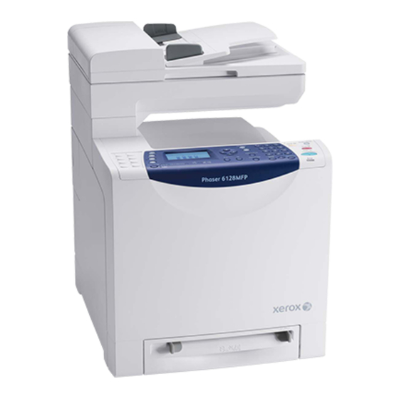
Page 28: Parts Of The Printer
General Information Parts of the Printer Front and Side Views s6128mfp-126 Automatic Document Feeder (ADF) Output Tray Front Door Release Power Switch Right Side Door Sheet Feeder Paper Tray Front Door Control Panel Phaser 6128MFP Service Manual... -
Page 29: Rear View
General Information Rear View s6128mfp-127 ADF Cover ESS Cover USB Port Ethernet Port Phone Line out Phone Line in Power test AC input Phaser 6128MFP Service Manual... -
Page 30: Internal View
General Information Internal View s6128mfp-128 Fuser Imaging Unit Toner Cartridges Transfer Belt Front Cover Release Phaser 6128MFP Service Manual... -
Page 31: Control Panel
Control Panel The Control Panel consists of multiple LEDs, a display, and several function buttons. These buttons are used to navigate the menu system, perform functions, and select modes of operation. Control Panel Button Descriptions s6128mfp-129 Phaser 6128MFP Service Manual... - Page 32 When illuminated, it indicates that there is a job in the printer’s memory. Color Mode button Press to switch between Color and Black and White modes for your copy, fax, and scan job. One touch keypad Use to dial stored speed-dial numbers. Phaser 6128MFP Service Manual...
-
Page 33: Maintenance Items
Print life is based on “typical” office printing and 5% coverage per color on 24 lb. paper. Print life figures are not guaranteed and varies depending on usage habits. Imaging Unit print life is based on 3-page jobs using letter-size paper. Phaser 6128MFP Service Manual... -
Page 34: Consumables
Gray scale. Internal counters track consumables and maintenance life. Life ratings are based on A-size sheets at 5% coverage. Toner Cartridge Print Life C,M,Y Black Standard Capacity 1,000 pages 1,000 pages High Capacity 2,500 pages 3,100 pages 1-10 Phaser 6128MFP Service Manual... -
Page 35: Specifications
Less than 30 seconds from Power On Operating System Windows 2000/ 2003 Server/ XP Pro/ XP/ Vista Macintosh OS 10.2 or higher Linux Redhat, SuSe, and TurboLinux 10 Desktop * Assumes a 30 day month of printing. Phaser 6128MFP Service Manual 1-11... -
Page 36: Scanning Specifications
Up to 6 SMB servers Scan to FTP Up to 6 FTP servers Scan to E-mail Yes (no individual user log in) Network Scan to Document Glass, 9 sec. Computer via SMB 150 dpi, mixed, letter size 1-12 Phaser 6128MFP Service Manual... -
Page 37: Copy Specifications
Off, Normal, Higher (1, 2) Number of Copies 1-99 Multiple Up (N to 1) Off, Auto, ID Copy, Manual Duplex Copy On, Off Poster 2x2, 3x3, 4x4 Auto Fit On, Off Cloning On, Off Collate Color: 19 B/W: 50 Phaser 6128MFP Service Manual 1-13... -
Page 38: Fax Specifications
Super Fine: 400 x 400 dpi Driver PCL driver - supported PS driver - not support Color Not support Delayed Start Up to 24 hours Broadcast Sending Up to 30 destinations Zoom 25%-400% (same as printer driver) 1-14 Phaser 6128MFP Service Manual... -
Page 39: Memory Specifications
Power Consumption (with all options, 110 or 220 V) Power Saver Mode 18.4W or less Standby Mode (Fuser On) 60W or less Color Continuous Printing 360W or less B/W Continuous Printing 360W or less Maximum Value 1100 W or less Phaser 6128MFP Service Manual 1-15... -
Page 40: Print Speed
Humidity (% RH) Operating 15 to 85% RH Standby 5 to 85% RH Altitude Operating 0 to 3,100 meters (10,171 feet) Acoustic Noise LWA(B) Sound Power Level (B) Sound Pressure (dBA) Printing 6.16 51.6 Standby 25.7 1-16 Phaser 6128MFP Service Manual... -
Page 41: Operating Mode
LCD: Off, LCD Backlight: Off Operation LED: Power Saver LED is turned On. NOTE When the printer receives a print job or a button is pressed, the printer exits the Power Saver mode and enters the Ready mode. Phaser 6128MFP Service Manual 1-17... -
Page 42: First Print Output Time (Fpot)
Paper is A size Short-Edge Feed (SEF). • Document is on the document glass (Document setting: Platen mode). • Media: Media feed from the standard media tray. Mode FCOT (sec.) Color Less than 30.0 sec. Mono Less than 21.0 sec. 1-18 Phaser 6128MFP Service Manual... -
Page 43: Image Specifications
Horizontal Duplex 234 mm ± 0.8 mm Vertical Simplex 190 mm ± 0.5 mm Vertical Duplex 190 mm ± 0.8 mm Registration Leading Edge 10.0 mm ± 2.0 mm Side Edge 8.5 mm ± 2.5 mm Phaser 6128MFP Service Manual 1-19... -
Page 44: Physical Dimensions And Clearances
25 kg (55 lb.) without consumables) Minimum Clearances 320 mm/ 12.60 inches 585 mm/ 23.03 inches 100 mm/ 3.94 inches 507 mm/ 19.96 inches 250 mm/ 9.84 inches 600 mm/23.62 inches 425 mm/16.73 inches 100 mm/3.94 inches s6128mfp-131 1-20 Phaser 6128MFP Service Manual... -
Page 45: Mounting Surface Specifications
Known problems that occur as a result of exceeding the mounting surface specifications are: • Color-to-Color mis-registration, primarily in the horizontal (laser scan) direction. • A smear or line of toner approximately 40 mm from the trailing edge of the print. Phaser 6128MFP Service Manual... -
Page 46: Media And Tray Specifications
General Information Media and Tray Specifications The following tables list the recommended Xerox paper for the printer. Supported Paper Size Paper Type Dimension Manual Feed Tray Letter 8.5 x 11 in. Legal 8.5 x 14 in. US Folio 8.5 x 13 in. -
Page 47: Controller Functions
50 users. RAM Disk RAM Disk functions when memory is expanded, enabling Collation, Secure Print, Proof Print, Form Overlay, and Font Download. 256 MB is needed to enable RAM Disk and all related functions. Collation Phaser 6128MFP Service Manual... - Page 48 Off. This function is not available for MAC OS 10.2 and Linux operating systems. Form Overlay The function for writing PCL6 forms are downloaded into RAM Disk. Font Download PCL6 fonts can be downloaded into RAM Disk. Phaser 6128MFP Service Manual...
-
Page 49: Non-Genuine Mode
Xerox (TM) Replace Empty Prints with full Toner Toner Soon functionality up to Cartridge) Cartridge 40% of the Toner Cartridge life. Other OEM Non-Xerox Printer displays error (non-Xerox Toner and will not print. printer Cartridge manufacturer) Phaser 6128MFP Service Manual... -
Page 50: Maintenance Function
1. Auto Diagnostics: The printer is checked when it is turned on. It is checked whether hardware (ROM, RAM, ASIC, etc..) operates properly. 2. Manual Diagnostics: Only qualified service personnel can perform manual diagnostics using the Service Mode in the Control Panel. Phaser 6128MFP Service Manual... -
Page 51: Information Pages
Version, Boot Version, Engine Version, PostScript CRD Version, Default Paper, Default Language, Current Temperature, Current Humidity Print Volume Print Volume for each paper size Network Setup Firmware Version, MAC Address, Ethernet, TCP/IP, Protocol, Host Access List, Adobe Protocol Phaser 6128MFP Service Manual... - Page 52 Language, Auto Log Print, Print ID, Print Text, Banner Sheet, RAM Disk, Tray Switching, mm/inch, Start Up Page Maintenance Auto Reg Adj., Non-Xerox Toner Paper Tray, Paper Size, Orientation, 2-Sided, Font, Symbol Set, Font Size, Font Pitch, Form Line, Quantity, Image Enhance, Hex Dump, Draft...
- Page 53 10/30/2008 11:13 IOT Remain Registration Jam Page:1(Last Page) XEROX CORPORATION and Fui Xerox Co., Ltd. 2008 Print Meter (Print Volume Report) The Print Meter page contains, Date of Initialization, Job Accounting User Name, Pages, Sheets, and Date/Time. Phaser 6128MFP Service Manual...
- Page 54 General Information 1-30 Phaser 6128MFP Service Manual...
-
Page 55: Theory Of Operation
Theory of Operation In this chapter... • Phaser 6128MFP Operational Overview • Printing Process • Media Path • Major Assemblies and Functions • Printer Modes • Printer Control • Drive Transmission Chapter... -
Page 56: Phaser 6128Mfp Operational Overview
Theory of Operation Phaser 6128MFP Operational Overview The Phaser 6128MFP is a full-color multifunction printer that uses raster output scanner (ROS) lasers with an electrophotographic four-color CMYK process. The tandem system consists of four color drums (C, M, Y, and K) which creates the toner image. -
Page 57: Printing Process
Exit Pinch Roller (Fuser) Exit Roller (Fuser) Heat Roller (Fuser) Fuser Belt (Fuser) Fuser BTR (Printer) BTR (Printer) BTR (Printer) BTR (Printer) Drive Roller (Printer) BCR (PHD) Drum (PHD) BCR Cleaner Roller (PHD) Magnet Roller (PHD) s6128mfp-002 Phaser 6128MFP Service Manual... -
Page 58: Charging
(which is an insulator in a dark area and a conductor when receiving light) and the drum inside is composed of conductor. The cleaning roller is a sponge that contacts the BCR to catch the toner. Photoreceptor Conductor Cleaning Roller Drum HVPS s6128mfp-003 Phaser 6128MFP Service Manual... -
Page 59: Exposure
The area on the surface where the laser beam strikes becomes conductive. The negative charge on the surface flows to the more positive drum, lowering the voltage potential. In this way the surface areas exposed to the laser beam become the electrostatic latent image. Phaser 6128MFP Service Manual... - Page 60 Laser Unit Negative Electric Charge Positive Electric Charge Photoreceptor Conductor Laser Beams Drum Surface Drum Laser Beam Electrostatic Latent Image Concept of Drum Electrostatic Potential on Laser Beam Latent Image Drum Surface Laser Beam Photoreceptor Conductor s6128mfp-005 Phaser 6128MFP Service Manual...
-
Page 61: Development
(electrostatic latent image) where the negative charge is lower than the charge on the magnet roller, forming the toner image on the drum. Once the toner adheres to the drum, the negative charge of the toner-bearing location increases, which decreases the potential and the toner-attracting force. Phaser 6128MFP Service Manual... -
Page 62: Transfer (Drum
The toner is transferred onto the paper in the order of Y, M, C, and K. Drum Surface (Black Toner Image) Drum Surface (Cyan Toner Image) Paper Black Toner Image Cyan Toner Image Drum Surface Magenta (Magenta Toner Image) Toner Image Yellow Toner Image Drum Surface (Yellow Toner Image) s6128-008 Phaser 6128MFP Service Manual... -
Page 63: Imaging Unit
Erase Lamp (LED) to prepare the drum for the next Exposure cycle. : Positive Electric Charge : Negative Electric Charge : Toner Erase Lamp (LED Assembly) Blade Conductor Photoreceptor Drum Cleaning Roll s6128-009 Phaser 6128MFP Service Manual... -
Page 64: Excess Toner Collection
The excess toner is collected by the cleaner blade contacting the drum and is moved to the Toner Cartridge collection box by two augers. Auger Cleaning Side Collection Box Toner Cartridge Auger Cleaner Blade s6128mfp-010 2-10 Phaser 6128MFP Service Manual... -
Page 65: Fusing
Toner is fused onto the media by the combination of heat and pressure. Warm-Up Stand By Printing Main Heater Lamp On/Off Nip Head Nip Spring Paper Felt Belt Belt Frame Fixed Toner Heat Roller Heater Lamp Sheet Unfixed Toner s6128-011 Phaser 6128MFP Service Manual 2-11... -
Page 66: Media Path
Feed Prevention Motor Drive/ Solenoid/Feed Roller Leading Edge Registration Assembly Registration (Except SSI) Motor Drive/Clutch/ Registration Roller Transfer Belt Motor Drive/Belt Fuser Motor Drive/Heat Roller/ Pressure Belt Exit Roller in the Fuser Top Cover s6128-012 2-12 Phaser 6128MFP Service Manual... -
Page 67: Media Path Components
: Paper Transfer : Paper Sensors Exit Roller Exit Sensor Heat Roller Pressure Belt Belt Rubber Registration Roller Metal Registration Roller Manual Feed No Paper Sensor Registration Sensor Separator Roller Feed Roller Tray No Paper Sensor s6128mfp-013 Phaser 6128MFP Service Manual 2-13... -
Page 68: Major Assemblies And Functions
The side guides move at a right angle to the paper transfer direction to align the paper width. • Tray End Guide The end guide moves in toward the paper transfer direction to determine the paper size. 2-14 Phaser 6128MFP Service Manual... - Page 69 Separator Roller at rest. The Separator Roller is pushed toward the Feed Roller by spring pressure, and controlled by the Friction Clutch. Feed Roller Separator Roller Friction Clutch Separator Roller s6128-015 Phaser 6128MFP Service Manual 2-15...
-
Page 70: Feeder
Theory of Operation Feeder Feed Roller Tray No Paper Sensor Feed Solenoid s6128mfp-016 • Tray No Paper Sensor Detects the presence/absence of paper in the Tray based on the position of No Paper Actuator. 2-16 Phaser 6128MFP Service Manual... - Page 71 The Feed Solenoid transmits drive energy from the Main Drive Assembly to the Feed Roller. • Feed Roller When the Feed Solenoid operates, it allows the Feed Roller to rotate and feed the paper. Main Drive Feed Roller Drive Feed Roller Feed Solenoid s6128-018 Phaser 6128MFP Service Manual 2-17...
-
Page 72: Manual Feed & Registration
The Registration Sensor detects paper when the paper leading edge reaches the registration chute. When paper is fed from the manual feed slot, the Registration Sensor measures the paper length. The On time of the Registration Sensor determines the media length. 2-18 Phaser 6128MFP Service Manual... - Page 73 Rear View Front Registration Registration Roller Actuator Output Actuator Registration Output Spring Registration Sensor Registration Input Actuator Registration Actuator Spring Metal Registration Roller Registration Sensor Registration Clutch Rubber Registration Roller s6128-020 Phaser 6128MFP Service Manual 2-19...
- Page 74 The printer doesn’t have switches for detecting paper size, and the length of paper is detected only by the Registration Sensor when feeding paper. If printing data and paper size don’t match, an error is sent to the Image Processor board. 2-20 Phaser 6128MFP Service Manual...
- Page 75 Roller Actuator Sensor Registration Sensor Registration Input Actuator Paper From Manual Sheet Feed Paper Detection: Trailing Edge Paper Registration Registration Roller Roller Actuator Actuator Paper Registration Registration Registration Registration Sensor Input Actuator Input Actuator Sensor s6128-023 Phaser 6128MFP Service Manual 2-21...
-
Page 76: Transfer Belt And Fuser
The Belt feeds the paper toward the direction of the Fuser. • ADC Sensor The ADC Sensor detects the toner patches on the Belt and converts them to voltage value. The voltage value is used to control the density of toner. 2-22 Phaser 6128MFP Service Manual... -
Page 77: Laser Unit
The Exit Sensor detects passage of printed pages after fusing on the Actuator’s position changes. Laser Unit Rear View Mirror Polygon Mirror Scanner Front Mirror Laser Diode Board Lens Mirror SOS Board SOS Sensor Mirror Laser Unit Lens Windows s6128-025 Phaser 6128MFP Service Manual 2-23... - Page 78 The Lenses correct aberration. • Mirror The mirror directs the laser beam to the Imaging Unit. • Window The window is the area where the laser beams exit the Laser Unit. 2-24 Phaser 6128MFP Service Manual...
-
Page 79: Toner Cartridge & Dispenser
The CRUM Connector reads and writes the CRUM data. Printer specific information is stored in the CRUM. • Dispenser Motor (C/M/Y/K) The Dispenser Motor provides the drive for the Agitator and Auger in the Toner Cartridge, and supplies toner to the Developer. Phaser 6128MFP Service Manual 2-25... -
Page 80: Imaging Unit
Each drum is given a latent image to which toner is applied by the Developer. The resulting toner image is transferred to the paper. • CRUM Information specific to the Developer/Imaging unit is stored in the CRUM. • Erase Lamp (LED) 2-26 Phaser 6128MFP Service Manual... -
Page 81: Drive
The drive consists of three assemblies: • Main Drive Assembly Drives the Imaging Unit, Transfer Belt, Registration Rollers, and Feeder. • Sub Drive Assembly Supplies drive to the Fuser and Developers (C, M, Y, K). Phaser 6128MFP Service Manual 2-27... - Page 82 Gear D3 In Sub Motor Full Color Mode Black And White Mode Color Mode Color Mode Switching Sensor Cam C Cam C Switching Sensor Gear C Gear C Color Mode Color Mode Switching Solenoid Switching Solenoid s6128-030 2-28 Phaser 6128MFP Service Manual...
-
Page 83: Electrical
MCU Board Humidity Sensor IP Board Multi Protocol HVPS Network Card (MPC) s6128mfp-031 The Fan removes heat from the printer to prevent overheating. Power Switch The Power Switch turns the printer AC Power Supply On/Off. Phaser 6128MFP Service Manual 2-29... - Page 84 High-Voltage Power Supply (HVPS) The HVPS provides high-voltage power to the components in the transfer belt and Imaging Unit to perform charging, development, and primary transfer of the print process to the BCR, BTR, and Developer. 2-30 Phaser 6128MFP Service Manual...
- Page 85 When installing a new I/P Board in the printer, you must transfer the following parts from the old board to the new board: • Memory DIMM • FAX Board Humidity /Temperature Sensor The Humidity/Temperature Sensor reads the humidity and temperature within the printer. Phaser 6128MFP Service Manual 2-31...
- Page 86 Machine Control Unit (Electric Signal) Laser Unit (Laser Beams) Laser Unit Imaging Unit Electrostatic Latent On Drum (Invisible Image) Imaging Unit Toner Image On Drum Toner Image On Paper Transfer Belt Fuser Print Image On Paper s6128-034 2-32 Phaser 6128MFP Service Manual...
-
Page 87: Printer Modes
Therefore, the laser beam light quantity is monitored and controlled by the laser diodes. The Laser Unit has four laser diodes for Yellow, Magenta, Cyan, and Black respectively and the beam intensity is automatically adjusted for each color. Phaser 6128MFP Service Manual 2-33... -
Page 88: Process Control
The toner dispense quantity is calculated by the toner dispense time. This calculation is made for each color. 2-34 Phaser 6128MFP Service Manual... -
Page 89: Color Registration Control
2. The patches for color registration control are generated on the Belt. These patches are composed of 10 mm lines of K, C, K, M, K, and Y in this order by the amount of four dispense counts, led by a black trigger. Phaser 6128MFP Service Manual 2-35... -
Page 90: Fuser Control
Heat Roller temperature distribution can be uniform. When the temperature of the Heat Roller edge is high, cooling down is performed to lower the temperature to the target value. 2-36 Phaser 6128MFP Service Manual... -
Page 91: Drive Transmission
Imaging Unit Gear 2 [ Drum (C) ] [ Drum (Y) ] HSG Xerographics (C) HSG Xerographics (Y) [ Drum (K) ] [ Drum (M) ] HSG Xerographics (K) HSG Xerographics (M) Imaging Unit s6128-036 Phaser 6128MFP Service Manual 2-37... - Page 92 [ Belt ] Rubber Registration Gear Gear P5 Metal Registration Gear [ Metal Registration Roller ] Registration Feeder Chute Registration Clutch Feed Gear Front [ Registration Roller ] [ Feed Roller ] Feed Solenoid s6128-037 2-38 Phaser 6128MFP Service Manual...
-
Page 93: Sub-Drive Assembly
Gear P4-2 Color Mode Gear D3 In Magnet Gear (K) Gear C Switching Solenoid Cam C [ Magnet Roller (K) ] Gear D3 Out Flange D3 Hsg Assy Deve (K) Imaging Unit Imaging Unit Drive s6128-038 Phaser 6128MFP Service Manual 2-39... - Page 94 Imaging Unit Gear D4 Gear D3 Out Gear P2 Cam C Flange D3 Flange D3 Main Drive Cam C Print Cartridge Drive Gear P3 Gear C Gear P4 Color Mode Gear P4-2 Switching Solenoid s6128-039 2-40 Phaser 6128MFP Service Manual...
- Page 95 [ Magnet Roll (K) ] [ Magnet Roll (C) ] [ Magnet Roll (M) ] [ Magnet Roll (Y) ] Developer Developer Developer Developer Housing (M) Housing (Y) Housing (K) Housing (K) Imaging Unit s6128-040 Phaser 6128MFP Service Manual 2-41...
- Page 96 Gear D4 [ Magnet Roller (M) ] Developer (M) Magnet Gear (Y) Gear D5 [ Magnet Roller (Y) ] Imaging Unit Drive Developer (Y) Gear D2 Front Gear D3 In Gear D4 Gear D3 Out s6128-041 2-42 Phaser 6128MFP Service Manual...
- Page 97 [ Side Cleaning Auger ] [ Developer Paddle ] Auger Gear [ Auger Front ] Auger Gear [ Auger Rear ] Xerographics Housing (Y, M, C, K) Developer Housing (Y, M, C, K) Imaging Unit s6128-042 Phaser 6128MFP Service Manual 2-43...
- Page 98 [ Front Auger ] Magnet Gear [ Magnet Roller ] Imaging Unit Gear 2 [ Drum ] Imaging Unit Gear 1 Imaging Unit Gear 2 [ Drum ] Sub Drive Front Imaging Unit Main Drive s6128-043 2-44 Phaser 6128MFP Service Manual...
- Page 99 [ Agitator (K) ] Auger Idler Gear (K) Auger Gear (K) Toner Cartridge (C) [ Auger (K) ] Dispenser Motor (C) Toner Cartridge (M) Dispenser Motor (M) Toner Cartridge (Y) Dispenser Motor (Y) Right Left s6128-045 Phaser 6128MFP Service Manual 2-45...
- Page 100 Theory of Operation Fuser Drive Fuser Drive [ Name Of Moving Parts ] Sub Drive Heat Roller Idler Gear Heat Roller Gear Exit Idler Gear Exit Gear [ Heat Roller ] [ Exit Roller ] Fuser s6128-046 2-46 Phaser 6128MFP Service Manual...
- Page 101 [ Name Of Moving Parts ] : Indicates The Engagement Of Gears Exit Gear [ Exit Roller ] Fuser Exit Idler Gear Heat Roller Gear [ Heat Roller ] Heat Roller Idler Gear Sub Drive Front s6128-047 Phaser 6128MFP Service Manual 2-47...
-
Page 102: Scanner
The optical image reflected from the document reaches the Charged Coupled Device (CCD) image sensor via the light path. CVT Position Platen Registration Point (Home Position) Scanner Assy CCD Image Sensor Scanner Home Position Sensor s6128-048 2-48 Phaser 6128MFP Service Manual... - Page 103 Home Position Sensor, thus detecting the Registration position. • Cold Cathode Fluorescent Lamp (Exposure Lamp) The Cold Cathode Fluorescent Lamp exposes the document. • Charged Coupled Device Board The Charged Coupled Device (CCD) Board (Image Sensor) converts optical images into electrical signals. Phaser 6128MFP Service Manual 2-49...
- Page 104 Shading compensation compensates for pixel-by-pixel sensitivity variations and the non-uniformity of lamp light in the fast scanning direction. The AGC and AOC adjustment values are used to compensate for the image data read by the CCD Image Sensor. 2-50 Phaser 6128MFP Service Manual...
-
Page 105: Ccd Image Sensor
Drive Signal/ CCD Clock Scanner Sensor Signal CCD Board/Motor/ R G B Image Signal Sensor/Lamp Y M C K Message Signal/ Drive Signal Control Panel Switch/Display/LED Switch Signal Command Status Image Signal MCU Board s6128mfp-051 Phaser 6128MFP Service Manual 2-51... -
Page 106: Scanning On Document Glass
Scanner Assembly: • Exposure Lamp that illuminates light onto the document, • CCD Image Sensor that reads light reflected from the document, and • Lenses and mirrors comprising the light path for the optical image. 2-52 Phaser 6128MFP Service Manual... -
Page 107: Automatic Document Feeder
The ADF Board controls the sensors and motor in the ADF. • Feed Sensor The Feed Sensor is located downstream from the Feed Roller to detect completion of document feed. • Document Present: Shielded (blocked) • Document Absent: Unshielded (unblocked) Phaser 6128MFP Service Manual 2-53... -
Page 108: Adf Media Path
The Nudger Roller moves down and presses onto the media in the paper tray to enable media feed. The Nudger Roller moves down with normal rotation of the ADF Motor. Upon completion of media feed, the ADF Motor reverses rotation to return the Nudger Roller to its normal position. 2-54 Phaser 6128MFP Service Manual... - Page 109 Exposure Lamp at the CVT position. 3. As the image is scanned, media is fed and ejected by the Exit Roller that is driven by the ADF Motor. Takeaway Roller Exit Roller CVT Position s6128-058 Phaser 6128MFP Service Manual 2-55...
-
Page 110: Adf Drive
Gear E Gear H Gear D Gear F Gear I [ Exit Roll ] [ Takeaway Roll ] Gear G Spring Clutch [ Feed Roll ] Gear J [ Nudger Roll ] Feed Roller Assembly s6128-056 2-56 Phaser 6128MFP Service Manual... - Page 111 Gear J Gear D [ Exit Roller ] Gear C Gear C Gear C Gear B Gear B Gear B Gear H Gear H Gear H Gear A Gear I [ Takeaway Roller ] s6128-057 Phaser 6128MFP Service Manual 2-57...
-
Page 112: Fax
(G3 Fine), scanning resolution is 8 divisions per millimeter in the horizontal direction and 7.7 divisions per millimeter in the vertical direction, where the data amounts to approximately four million pixels. As resolution increases, the amount of data also increases, lengthening the transmission time. 2-58 Phaser 6128MFP Service Manual... - Page 113 Digital Signal Control Circuit Image Digital data Modem A/D Conversion Conversion Unit (Modulation) Sending FAX Analog Signal Telephone Line Control Circuit Receiving FAX Modem Conversion A/D Conversion (Demodulation) Unit Digital Signal Printer Print Printing s6128-060 Phaser 6128MFP Service Manual 2-59...
- Page 114 With data compression, any part of the scanned imaged data consisting of continuous or black pixels is encoded into a single element, thus compressing the volume of data. Memory temporarily stores data during transmission and reception. 2-60 Phaser 6128MFP Service Manual...
-
Page 115: Protocol Monitor
In order for a fax to be established, both ends of the line must recognize that the other end is a non-voice (Fax) terminal. Since G3 fax communication is intended for a transmission over the conventional voice network, a fax communication must be initiated via audible tones. Phaser 6128MFP Service Manual 2-61... - Page 116 Therefore, the session may show a looped sequence such as ABCDCD...E, ABCDBCDBCD...E. etc., depending on the remainder of the document or the transmission parameters for the subsequent page. 2-62 Phaser 6128MFP Service Manual...
- Page 117 Protocol Monitor allows the user to monitor and print the transmission/reception records of signals during a G3 fax session that is in conformance to the ITU-T Recommendation T.30, thereby helping to isolate fax communication issues. Phaser 6128MFP Service Manual 2-63...
- Page 118 Receiving side: From the transmission of CED signal to the detection of incoming DCN signal. The following illustrates the different Fax reports available and includes an example Protocol Monitor report with the descriptions of signals handled by Protocol Monitor. s6128mfp-327 2-64 Phaser 6128MFP Service Manual...
-
Page 119: Fax Standards (Itu-T Recommendations)
Image data in digital format. Data compression. Most common standard in use. Group 4 Approx. 3 sec. 400 x 400 dpi 64kbps Digital (G4) (using ISDN) transmission. Supported by various digital transmission services. Halftone supported. Phaser 6128MFP Service Manual 2-65... - Page 120 Theory of Operation 2-66 Phaser 6128MFP Service Manual...
-
Page 121: Error Messages And Codes
Error Messages and Codes In this chapter... • Introduction • Servicing Instructions • Messages, Codes, and Procedures • Jam Errors • Consumable/Routine Maintenance Errors • Tray and Media Errors • Configuration, Memory, and Firmware Errors • Email Errors • SMB Errors •... -
Page 122: Introduction
Jam and System (fatal) errors. The printer can retain up to 42 Jam errors and 42 System Fail errors. Examples of Error message and Chain Link code: • System Fail History • Chain Link: 018-310 • Paper Jam History • Paper Jam Type: IOT Remain Registration Jam Phaser 6128MFP Service Manual... - Page 123 Error History Report Date & Time : 10/30/2008 11:14 System Fail History Paper Jam History Date Time Paper Jam Type 10/30/2008 11:13 IOT Remain Registration Jam Page:1(Last Page) XEROX CORPORATION and Fui Xerox Co., Ltd. 2008 Phaser 6128MFP Service Manual...
-
Page 124: Servicing Instructions
1. Use the Parts List to locate a part number. 2. Use the FRU Disassembly procedures to replace the part. Step 5: Final Checkout 1. Test the printer to be sure you have corrected the initial problem and there are no additional problems present. Phaser 6128MFP Service Manual... -
Page 125: Messages, Codes, And Procedures
Machine Control Unit Multi-Function Device (IIT controller) Multi-Protocol Network Card Non-Volatile Memory. Used instead of NVRAM. NVRAM Non-Volatile Random Access Memory Printer Control Language Page Description Language Random Access Memory Registration Read Only Memory TRAN Transfer Belt Phaser 6128MFP Service Manual... -
Page 126: Error Message And Code Summary
Manageable Limit. MFD Controller Error <File Error> page 3-135 Controller Error 017-978 Document Page Count Press OK Button exceeds Limit. MFD Controller Error <File Error> page 3-135 Controller Error 017-979 File Double Open. Press OK Button Phaser 6128MFP Service Manual... - Page 127 <Commucation Error> page 3-133 Controller Error Communication Interrupted Error 033-513 due to Memory Full. Press OK Button Fax Codec Error <JPEG DNL/SOF0 Error> page 3-142 Controller Error 033-514 Line Number Unavailable at Press OK Button JPEG Reception. Phaser 6128MFP Service Manual...
- Page 128 3-134 Controller Error 033-524 ATMOVE> Press OK Button The unsupported Adaptive Template is executed. Fax Codec Error <JBF Error Marker Bad page 3-134 Controller Error 033-525 Newline> Press OK Button The unsupported Image Level is executed. Phaser 6128MFP Service Manual...
- Page 129 Error Error> Error 033-759 The Control Channel Retrain Press OK Button Error occurred. Fax Communication <Control Channel OFF Time page 3-137 Controller Error Out> Error 033-760 The Control Channel OFF time Press OK Button out occurred. Phaser 6128MFP Service Manual...
- Page 130 <Undefined Maker Error> page 3-134 Controller Error 033-772 The undefined marker was Press OK Button detected. Fax Codec Error <BIH Error> page 3-134 Controller Error 033-773 The BIH was abnormal at Press OK Button JBIG decoding. 3-10 Phaser 6128MFP Service Manual...
- Page 131 Press OK Button MFD Memory Full <Memory Full> page 3-133 Controller Error 033-788 Exceeds the memory capacity. Press OK Button Fax Job Canceled <Cancel> page 3-135 Controller Error 033-789 The Cancellation occurred. Press OK Button Phaser 6128MFP Service Manual 3-11...
- Page 132 3-148 Controller Error Exceeds the predetermined Error 035-705 value of the resending. Press OK Button Fax Communication <Fall Back Error> page 3-137 Controller Error The Fall Back error occurred. Error 035-706 Press OK Button 3-12 Phaser 6128MFP Service Manual...
- Page 133 3-148 Controller Error Exceeds the predetermined Error 035-737 value of the resending. Press OK Button Fax Communication <T5 Time Out> page 3-148 Controller Error The T5 Time Out error Error 035-739 occurred. Press OK Button Phaser 6128MFP Service Manual 3-13...
- Page 134 MFD Controller Error <Download Program Sum page 3-142 Controller Error 117-312 Error> Restart Printer The download program sum error occurred. Error 117-322 <SYSMGR Task Error> page 3-135 Controller Restart Printer The SYSMGR task error occurred. 3-14 Phaser 6128MFP Service Manual...
- Page 135 3-135 Controller Error Error> Error 133-231 The data processing interface Restart Printer error on T FAXCOM. Fax Error <JBIG Parameter Error> page 3-135 Controller Error 133-234 The JBIG parameter setting Restart Printer error occurred. Phaser 6128MFP Service Manual 3-15...
- Page 136 <Memory Pool Rerese Error> page 3-142 Controller Error 133-248 The Memory Pool release error Restart Printer occurred (OS error). Fax Error <Message Receive Error> page 3-142 Controller Error 133-249 The Message receive error Restart Printer occurred (OS error). 3-16 Phaser 6128MFP Service Manual...
- Page 137 Restart Printer Fax Error <File Open Error> page 3-142 Controller Error 133-276 The File Open error occurred. Restart Printer Fax Error <File Close Error> page 3-142 Controller Error 133-277 The File Close error occurred. Restart Printer Phaser 6128MFP Service Manual 3-17...
- Page 138 Controller <EEPROM R/W Error> page 3-142 Controller Initialized NVM EEPROM Read/Write error at system boot. Toner Copy, Scan Fax <IOT Y CRU Near Life> page 3-58 Yellow Low Yellow cartridge is near end of life. 3-18 Phaser 6128MFP Service Manual...
- Page 139 <IOT C CRU Detached> page 3-66 Print Cartridge The yellow cartridge is not Error 093-972 detected. Toner Insert Black <IOT K CRU Detached> page 3-66 Print Cartridge The yellow cartridge is not Error 093-973 detected. Phaser 6128MFP Service Manual 3-19...
- Page 140 POP3 Login Failed Failed to Login to POP3 Server Error 016-505 at Mail Transmission. Press OK Button Server Email Login Error <SMTP Error> page 3-118 Error 016-506 Required User Parameter Not Press OK Button Set. 3-20 Phaser 6128MFP Service Manual...
- Page 141 Press OK Button not allowed to login to SMB scan. Server SMB Login Error <SMB Error> page 3-120 Error 031-522 SMB user authentication has Press OK Button failed, or login to SMB scanner has failed. Phaser 6128MFP Service Manual 3-21...
- Page 142 SMB scan file could not be File Make Error successfully created. Press OK Button Server SMB Error <SMB Error> page 3-124 Error 031-534 SMB scan folder could not be Folder Make Error successfully created. Press OK Button 3-22 Phaser 6128MFP Service Manual...
- Page 143 Error 031-546 SMB protocol error (4-048): Press OK Button The user is invalid. Server SMB Login Error <SMB Error> page 3-124 Error 031-547 SMB protocol error (4-049): Press OK Button The user is locked out. Phaser 6128MFP Service Manual 3-23...
- Page 144 Press OK Button The login name or password for FTP scan has a problem. Server FTP Path Error <Migration to RepositoryPath page 3-124 Error 031-579 failed> Press OK Button Image storage problem on FTP scan server. 3-24 Phaser 6128MFP Service Manual...
- Page 145 Administra TYPE Command Error FTP scan. tor. Press OK Button Server FTP Error <PORT command failed> See System Error 031-595 The PORT command failed on Administra PORT Command Error FTP scan. tor. Press OK Button Phaser 6128MFP Service Manual 3-25...
- Page 146 Checksum error in main Restart Printer program ROM is detected. RAM Error <ESS DIMM Slot RAM Power page 3-116 Error 116-320 On Initializing Fail > Restart Printer Error in on I/P Board DIMM RAM during initialization. 3-26 Phaser 6128MFP Service Manual...
- Page 147 A fatal error occurred in Contact Support File2Net. If Message Returns 131-398 Scan <SMB Error> Cycle Restart Printer A fatal error occurred in system Contact Support SMBclient. power. If If Message Returns the error persists, page 3-114 Phaser 6128MFP Service Manual 3-27...
- Page 148 The ESSSUB1 task error occurred. System Error 117-354 <ESSMGR Task Error> page 3-117 Restart Printer Failed in AIF SET. System Error 117-355 <ESSMGR Task Error> page 3-117 Restart Printer The Service Function-ID out of range.. 3-28 Phaser 6128MFP Service Manual...
- Page 149 <Parameter Error> page 3-129 Error 062-322 Abnormality of the parameter. Restart Printer Memory Full <IIT Memory Over Flow> page 3-128 Error 062-324 The amount of scanning data Add Memory exceeded memory capacity. Press OK Button Phaser 6128MFP Service Manual 3-29...
- Page 150 <IOT Side 2 No paper> page 3-80 continue Media was not reloaded into manual feed slot for duplex printing. Remove paper from <IOT SSF No Paper> page 3-81 Manual Feed Waiting for reseat media in manual feed slot. 3-30 Phaser 6128MFP Service Manual...
- Page 151 <No suitable paper in SSF> page 3-81 XXX(Paper Size) No media in manual feed slot. Load Manual Feed YYY(Paper Type) Media Press OK Button to <No suitable paper in SSF> page 3-81 continue No media in manual feed slot. Phaser 6128MFP Service Manual 3-31...
- Page 152 Fan Motor Error <IOT Fan Motor Failure> page 3-103 Error 042-328 Fan Motor failure detected. Restart Printer Fuser Replace Fuser <IOT Fuser Life Over> page 3-54 010-351 Printer Fuser has reached end of life. Replace Fuser 3-32 Phaser 6128MFP Service Manual...
- Page 153 3-53 005-124 The ADF Jam occurred when Open ADF Cover and the job was cancelled. Remove Document Scanner ADF Cover R <ADF Cover Open> page 3-108 Open The ADF Cover is open. Close ADF Cover Phaser 6128MFP Service Manual 3-33...
- Page 154 <Download Error> page 3-114 Error 016-500 An error was detected at Flash Restart Printer memory erasing. Other Write Flash Error <Download Error> page 3-114 Error 016-501 An error was detected at Flash Restart Printer memory writing. 3-34 Phaser 6128MFP Service Manual...
- Page 155 Press OK Button communication error detected.. Other Invalid User <Auditron-Invalid User> page 3-86 Error 016-757 Account error occurs. Press OK Button Other Disabled Func <Auditron-Disabled Function> page 3-86 Error 016-758 Disabled function is selected. Press OK Button Phaser 6128MFP Service Manual 3-35...
- Page 156 Restart Printer detected. Code:XX 01: Humid Sensor Error 02: Temp. Sensor Error 03: Humid/Temp Sensors Error Other Copy, Scan, Fax, Non- <Custom Toner Mode> page 3-68 Xerox Toner The printer is in custom toner mode. 3-36 Phaser 6128MFP Service Manual...
-
Page 157: Jam Errors
Jam at Exit Open Front Cover Initial Actions • Check the media path for obstructions or debris. • Check the condition of the Feed and Seperator Rollers. • Cycle printer power. • If the problem persists, follow the procedure below. Phaser 6128MFP Service Manual 3-37... - Page 158 Go to step 9. wear. Feed Roller Is the Feed Roller damaged or worn? (page 8-10). Run the Tray Feed Solenoid test (DO- Replace the Go to step 18. 2F) on (page 4-49). Tray. Does the solenoid operate? 3-38 Phaser 6128MFP Service Manual...
- Page 159 Are the connectors secure? Check Left Side Harness continuity. Repair or Go to step 20. Disconnect P/J23 from the MCU replace the Board and P/J231 from the Feed harness Solenoid. (PL10.4.18). Is the harness damaged? Phaser 6128MFP Service Manual 3-39...
- Page 160 Interlock Switch is closed? Check Registration Clutch resistance. Replace the Replace the Disconnect P/J262 from the Feed MCU Board Registration Solenoid (page 8-57). Clutch Is the resistance across J262-1 and (page 8-35). J262-2 about 280 Ohms? 3-40 Phaser 6128MFP Service Manual...
-
Page 161: Jam At Front Cover
Feed No Paper Sensor. (PL10.4.18). Is the harness damaged? Check for +3.3 V at J23 on the MCU Go to step 6. Replace the Board. MCU Board Is +3.3 V available between J23-6 (page 8-57). <=> ground? Phaser 6128MFP Service Manual 3-41... - Page 162 Check No Paper Sensor signal. Replace the Replace the Does the voltage between ground MCU Board Manual Feed <=>J23-8 on the MCU Board change (page 8-57). No Paper when the actuator blocks the Sensor sensor? (page 8-28). 3-42 Phaser 6128MFP Service Manual...
-
Page 163: Jam At Front Cover Open Front Cover And Remove Paper
Registration Rollers operate? Run the Registration Sensor test (DI- Replace the Go to step 5. 02) (page 4-35). MCU Board Use the Registration Actuator In to (page 8-57). toggle the sensor output. Does the sensor operate? Phaser 6128MFP Service Manual 3-43... - Page 164 Interlock Switch is closed? Check Registration Clutch resistance. Replace the Replace the Disconnect P/J262 from the Feed MCU Board Registration Solenoid (page 8-57). Clutch Is the resistance across J262-1 and (page 8-35). J262-2 about 280 Ohms? 3-44 Phaser 6128MFP Service Manual...
-
Page 165: Jam At Exit
Are the connectors secure? Check the Fuser Harness continuity. Repair or Go to step 4. Disconnect P/J17 from the MCU replace the Board and P/J171 from the frame. harness Is the harness damaged? (PL6.1.2). Phaser 6128MFP Service Manual 3-45... - Page 166 J17-1 pin on the MCU Board? Check exit sensor signal. Replace the Replace the Does the voltage between ground MCU Board Fuser <=>J17-3 on the MCU Board change (page 8-57). (page 8-11). when the exit sensor actuator blocks the sensor? 3-46 Phaser 6128MFP Service Manual...
-
Page 167: Jam At Manual Feed Slot
Run the Main Motor test (DO-00) on Go to step 4. Go to step 15. (page 4-41). Does the motor rotate? Does the media reach the Go to step 5. Go to step 7. Registration Rollers when fed from the Tray? Phaser 6128MFP Service Manual 3-47... - Page 168 Check Manaul Feed Sensor signal. Replace the Replace the Does the voltage between ground MCU Board Manual Feed <=>J23-8 on the MCU Board change (page 8-57). Sensor when the actuator blocks the (page 8-27). sensor? 3-48 Phaser 6128MFP Service Manual...
- Page 169 Interlock Switch is closed? Check Registration Clutch resistance. Replace the Replace the Disconnect P/J262 from the Feed MCU Board Registration Solenoid (page 8-57). Clutch Is the resistance across J262-1 and (page 8-35). J262-2 about 280 Ohms? Phaser 6128MFP Service Manual 3-49...
-
Page 170: Jam At Registration Roller
Does the Front Cover latch correctly? replace the Front Cover (page 8-15). Check the Transfer Belt. Repair or Go to step 4. Is the Transfer Belt damaged or replace the misaligned? Transfer Belt (page 8-103). 3-50 Phaser 6128MFP Service Manual... - Page 171 Registration Actuator In is (page 8-29). used to block the sensor? Check connectors P/J26 and P/J262 Go to step 14. Reconnect the between the MCU Board and connectors. Registration Clutch. Are the connectors secure? Phaser 6128MFP Service Manual 3-51...
- Page 172 Check for +24 V at J21 on the MCU Replace the Replace the Board. Main Drive MCU Board Is +24 V available at J21-2 and J21- Assembly (page 8-57). 4 when the Interlock Switch is (page 8-58). closed? 3-52 Phaser 6128MFP Service Manual...
-
Page 173: Jam At Scanner
Check the connectors P/J1002 and Go to step 5. Secure the P/J1003 on the I/P Board. connectors. Are the connections secure? Replace the ADF Assembly Replace the I/P Complete. (page 8-79). Board Does the error persist? (page 8-41). Phaser 6128MFP Service Manual 3-53... -
Page 174: Consumable/Routine Maintenance Errors
Go to step 3. Reseat the Fuser. Cycle system power. Go to step 4. Complete. Does the error persist. Replace the Fuser (page 8-11). Replace the Complete. Does the error still occur? MCU Board (page 8-57). 3-54 Phaser 6128MFP Service Manual... -
Page 175: Fuser Error
Check the LVPS Harness for continuity. Go to step 4. Replace the LVPS Disconnect P/J501 from the LVPS. Disconnect P/J14 from the MCU Board. Harness. Check continuity between P/J501 <=> P/ J14. Is the harness damaged? Phaser 6128MFP Service Manual 3-55... -
Page 176: Reseat Fuser Error
“Fuser” on page 10-21 Fuser Harness, PL10.8.6 Troubleshooting Procedure Step Actions and Questions Check the connectors P/J17 and P/J171 Go to step 2. Reconnect between the MCU Board and the Fuser. Are the connectors secure? connectors. 3-56 Phaser 6128MFP Service Manual... - Page 177 Is there a measurable resistance between each pair of pins? Replace the Fuser (page 8-11). Replace the Complete. Does the error persist? MCU Board (page 8-57). NOTE Reset the Fuser life counter after installation of a new Fuser. Phaser 6128MFP Service Manual 3-57...
-
Page 178: Toner Cartridge Errors
Toner Cartridge PL5.1.21~24 “Toner Dispense” on page 10-20 MCU Board, PL10.7.7 Troubleshooting Procedure Table Step Actions and Questions Replace the Toner Cartridge Replace the Complete. (page 8-13). MCU Board Does the error persist? (page 8-57). 3-58 Phaser 6128MFP Service Manual... -
Page 179: Low Density Yellow Cartridge Error
Low Density Yellow Cartridge Initial Actions • Check that the cartridge is a genuine Xerox Toner Cartridge. If not, replace with a genuine Xerox cartridge. • Check the Toner Cartridge life cycle count. If at or near end of life, replace the cartridge. -
Page 180: Low Density Magenta Cartridge Error
Low Density Magenta Cartridge Initial Actions • Check that the cartridge is a genuine Xerox Toner Cartridge. If not, replace with a genuine Xerox cartridge. • Check the Toner Cartridge life cycle count. If at or near end of life, replace the cartridge. - Page 181 (page 8-91) Replace the Imaging Unit Go to step 7. Complete. (page 8-8). Does the error persist? Reseast the Transfer Belt at the Replace the Complete Front Cover. Transfer Belt Does the error persist? (page 8-103) Phaser 6128MFP Service Manual 3-61...
-
Page 182: Low Density Cyan Cartridge Error
Low Density Cyan Cartridge Initial Actions • Check that the cartridge is a genuine Xerox Toner Cartridge. If not, replace with a genuine cartridge. • Check the Toner Cartridge life cycle count. If at or near end of life, replace the cartridge. -
Page 183: Low Density Black Cartridge Error
Low Density Black Cartridge Initial Actions • Check that the cartridge is a genuine Xerox Toner Cartridge. If not, replace with a genuine cartridge. • Check the Toner Cartridge life cycle count. If at or near end of life, replace the cartridge. - Page 184 (page 8-91) Replace the Imaging Unit Go to step 7. Complete. (page 8-8). Does the error persist? Reseast the Transfer Belt at the Replace the Complete Front Cover. Transfer Belt Does the error persist? (page 8-103) 3-64 Phaser 6128MFP Service Manual...
-
Page 185: Non-Xerox Toner Cartridge Error
Error Messages and Codes Non-Xerox Toner Cartridge Error A Toner Cartridge CRUM ID error indicates a non-Xerox cartridge is installed. The following troubleshooting procedure applies to these errors. Applicable Errors • 093-960: Non-Xerox Toner Yellow Print Cartridge • 093-961: Non-Xerox Toner Magenta Print Cartridge •... -
Page 186: Insert Cartridge Error
093-972: Insert Cyan Cartridge • 093-973: Insert Black Cartridge Initial Actions • Check that the cartridge is a genuine Xerox Toner Cartridge. If not, check the Toner Type setting. Set to Non-Xerox Toner if necessary. • Check installation of the Toner Cartridge. •... - Page 187 Is +3.3 V available at the indicated CRUM connector? Check for +3.3 V at P/J14 on the Replace the Replace the MCU Board. MCU Board LVPS Is 3.3 V available at P14-12? (page 8-57). (page 8-47). Phaser 6128MFP Service Manual 3-67...
-
Page 188: Non-Xerox Toner
Error Messages and Codes Non-Xerox Toner The Printer does not have a genuine Xerox Print Cartridge installed. The following troubleshooting procedure applies to this error. Applicable Error • Non-Xerox Toner Initial Actions • Check the Toner Cartridge manufactuer. • Cycle printer power. -
Page 189: Iu Crum Error
Repair the Go to step 2. harness. harness. Disconnect P/J42 and P/J422 and check continuity. Is the harness damaged? Replace the Imaging Unit Replace the Complete. (page 8-8). MCU Board Does the error persist? (page 8-57).. Phaser 6128MFP Service Manual 3-69... -
Page 190: Imaging Unit Life, Replace Imaging Unit Error
Troubleshooting Procedure Table Step Actions and Questions Replace the Imaging Unit Replace the Complete. (page 8-8). MCU Board (page 8-57).. NOTE Remove the 8 sealing tapes from the new Imaging Unit before installation. Does the error persist? 3-70 Phaser 6128MFP Service Manual... -
Page 191: Check Imaging Unit Error
Does the error persist? Replace the Imaging Unit Replace the Complete. (page 8-8). MCU Board (page 8-57).. NOTE Remove the 8 sealing tapes from the new Imaging Unit before installation. Does the error persist? Phaser 6128MFP Service Manual 3-71... -
Page 192: Insert Imaging Unit Error
Is the harness damaged? Replace the Imaging Unit Replace the Complete. (page 8-8). MCU Board (page 8-57). NOTE Remove the 8 sealing tapes from the new Imaging Unit before installation. Does the error persist? 3-72 Phaser 6128MFP Service Manual... -
Page 193: Tray And Media Errors
Use the actuator to toggle the (page 8-57). sensor output. Does the sensor operate? Check connectors P/J23 and P/J234 Go to step 4. Reconnect the between the MCU Board and the No connectors. Paper Sensor. Are the connectors secure? Phaser 6128MFP Service Manual 3-73... - Page 194 Does the voltage between ground MCU Board Manual Feed <=>J23-8 on the MCU Board change (page 8-57).If No Paper when the actuator blocks the the error Sensor sensor? persists, replace (page 8-28). the I/P Board (page 8-41) 3-74 Phaser 6128MFP Service Manual...
-
Page 195: Load Tray Or Illegal Settings
Does the display change when the Actuator is activated? Check the wiring harness connectors Go to step 5. Reconnect the P/J23, P/J234 between the No Paper connectors. Sensor and the MCU Board. Are the connections secure? Phaser 6128MFP Service Manual 3-75... - Page 196 Replace the Replace the No Measure the voltage across ground MCU Board Paper Sensor <=> J23-11 on the MCU Board. (page 8-57). (page 8-33). Does the voltage change when the No Paper Sensor is activated? 3-76 Phaser 6128MFP Service Manual...
-
Page 197: Insert Output To Tray
Is the harness damaged? Check for +3.3 V at J23 on the MCU Go to step 5. Replace the Board. MCU Board Is +3.3 V available between J23-9 (page 8-57). <=> ground when the Interlock Switch is closed? Phaser 6128MFP Service Manual 3-77... -
Page 198: Check Manual Feed
Actions and Questions Was media removed from the Go to step 2. Go to step 3 manual feed slot during a print operation? Reload the manual feed slot. Go to step 3. Complete. Does the error persist? 3-78 Phaser 6128MFP Service Manual... - Page 199 Check No Paper Sensor signal. Replace the Replace the Does the voltage between ground MCU Board Manual Feed <=>J23-8 on the MCU Board change (page 8-57). No Paper when the actuator blocks the Sensor sensor? (page 8-28). Phaser 6128MFP Service Manual 3-79...
-
Page 200: Insert Output To Manual Feed
Feed No Paper Sensor. (PL10.4.18). Is the harness damaged? Check for +3.3 V at J23 on the MCU Go to step 6. Replace the Board. MCU Board Is +3.3 V available between J23-6 (page 8-57). <=> ground? 3-80 Phaser 6128MFP Service Manual... -
Page 201: Load Or Remove Paper From Manual Feed
Check the Manual Feed Sensor Repair or Go to step 2. Actuator for damage or replace the misalignment. Remove the Lower Manual Feed Chute (PL3.2.27) to examine the Sensor actuator. Actuator Is the actuator damaged or (page 8-28). misaligned? Phaser 6128MFP Service Manual 3-81... - Page 202 Check No Paper Sensor signal. Replace the Replace the Does the voltage between ground MCU Board Manual Feed <=>J23-8 on the MCU Board change (page 8-57). No Paper when the actuator blocks the Sensor sensor? (page 8-28). 3-82 Phaser 6128MFP Service Manual...
-
Page 203: Reseat Paper At Manual Feed
Front Cover (page 8-15). Run the Main Motor test (DO-0) on Go to step 4. Repair or (page 4-41). replace the Does the motor and Registration Main Drive Rollers rotate? Assembly (page 8-58). Phaser 6128MFP Service Manual 3-83... -
Page 204: Registration Roller Actuator, Pl3.3.8
Check Manual Feed Sensor signal. Replace the Replace the Does the voltage between ground MCU Board Manual Feed <=>J23-8 on the MCU Board change (page 8-57). Sensor when the actuator blocks the (page 8-27). sensor? 3-84 Phaser 6128MFP Service Manual... - Page 205 Interlock Switch is closed? Check Registration Clutch resistance. Replace the Replace the Disconnect P/J262 from the Feed MCU Board Registration Solenoid (page 8-57). Clutch Is the resistance across J262-1 and (page 8-35). J262-2 about 280 Ohms? Phaser 6128MFP Service Manual 3-85...
-
Page 206: Configuration, Memory, And Firmware Errors
A disabled operation was attempted. This troubleshooting procedure applies to this error. Applicable Error • 016-758: Disabled Func Error Initial Actions • Check the print driver version. • Cycle printer power. • If the problem persists, follow the procedure below. 3-86 Phaser 6128MFP Service Manual... -
Page 207: Limit Exceeded Error
Cycle printer power. • If the problem persists, follow the procedure below. Troubleshooting Reference Table Applicable Parts Wiring and Plug/Jack Map References Image Processor Board, PL10.6.6 “Map 3 - Electrical and Drive” on page 10-8 Phaser 6128MFP Service Manual 3-87... -
Page 208: Invalid Job Error
Wiring and Plug/Jack Map References Image Processor Board, PL10.6.6 “Map 3 - Electrical and Drive” on page 10-8 Troubleshooting Procedure Table Step Actions and Questions Print a small size file. Go to step 2. Complete. Does the error persist? 3-88 Phaser 6128MFP Service Manual... -
Page 209: Mcu Firmware Error
“Map 1 - MCU Board” on page 10-6 Troubleshooting Procedure Table Step Actions and Questions Check the MCU Board installation. Replace the Check system Cycle system power. MCU Board electrical Does the error persist? (page 8-57). grounds. Phaser 6128MFP Service Manual 3-89... -
Page 210: Download Mode Error
“Map 1 - MCU Board” on page 10-6 MCU Board, PL10.7.7 Troubleshooting Procedure Table Step Actions and Questions Check the MCU Board installation. Replace the I/P Check system Cycle system power. Board electrical Does the error persist? (page 8-41). grounds. 3-90 Phaser 6128MFP Service Manual... -
Page 211: Pagec Timer Error
“Map 3 - Electrical and Drive” on page 10-8 Troubleshooting Procedure Table Step Actions and Questions Check the Image Processor Board Replace the I/P Complete. installation. Board Cycle system power. (page 8-41). Does the error persist? Phaser 6128MFP Service Manual 3-91... -
Page 212: Ram Disk Full Error
Does the memory amount listed (page 8-41). Configuration match the installed memory? page to check memory. Replace the memory card Replace the Complete. Does the error still occur? Image Processor Board (page 8-41). 3-92 Phaser 6128MFP Service Manual... -
Page 213: Collate Full Error
Configuration. and reprint the Does the memory amount listed Configuration match the installed memory? page to check memory. Partition the print job. Replace the Complete. Does the error still occur? Image Processor Board (page 8-41). Phaser 6128MFP Service Manual 3-93... -
Page 214: Firmware Errors
Complete. connection connection, then cycle system power. Does the error still occur? Reseat connections on the Image Replace the Complete. Processor Board, then cycle system Image power. Processor Board Does the error persist? (page 8-41). 3-94 Phaser 6128MFP Service Manual... -
Page 215: Mcu Communication Error
Disconnet P/J901 and P/J10 and Repair the Go to step 4. check the harness continuity. harness. Is the harness damaged? Replace the MCU Board (page 8-57). Replace the I/P Complete. Does the error persist? Board (page 8-41). Phaser 6128MFP Service Manual 3-95... -
Page 216: Mcu Nvram Error
Go to step 3. continuity. Disconnect: harness. J311 from the Yellow CRUM J312 from the Magenta CRUM J313 from the Cyan CRUM J314 from the Black CRUM J31 from the MCU Board Is the harness damaged? 3-96 Phaser 6128MFP Service Manual... - Page 217 Check for +3.3 V at the MCU Board Replace the Go to step 5. connector P/J42. EEPROM Board. Is there +3.3 V between P42-3 <=>ground? Reseat the MCU Board connections. Replace the Complete. Does the error persist? MCU Board (page 8-57). Phaser 6128MFP Service Manual 3-97...
-
Page 218: Electrical
Check for +5 V at J403 of the I/P Replace the Replace the I/P Board. Control Panel Board Is there +5 V between ground <=> (page 8-43). (page 8-41). J403-4 on the MCU Board when the Interlock Switch is closed? 3-98 Phaser 6128MFP Service Manual... -
Page 219: K Mode Sol Error
Is the resistance across J24-1 and MCU Board Feed Drive J24-2 80 to 110 Ohms? (page 8-57). Assembly (page 8-37). Check the solenoid connection. Go to step 7. Secure the Are P/J26 and P/J261 secure? connections. Phaser 6128MFP Service Manual 3-99... -
Page 220: Main Motor Error
Wiring and Plug/Jack Map References Main Drive, PL7.1.2 “Map 1 - MCU Board” on page 10-6 MCU Board, PL10.7.7 “Map 3 - Electrical and Drive” on page 10-8 Main Motor Harness, PL10.8.7 “Main Drive” on page 10-16 3-100 Phaser 6128MFP Service Manual... -
Page 221: Main Drive
Check for +24 V at J21 on the MCU Replace the Replace the Board. Main Drive MCU Board Is +24 V available at J21-2 and J21- Assembly (page 8-57). 4 when the Interlock Switch is (page 8-58). closed? Phaser 6128MFP Service Manual 3-101... -
Page 222: Sub Motor Error
Sub Drive to check continuity. (PL10.8.8). Is the harness damaged? Check the Sub Drive Assembly for Go to step 7. Reseat the Sub correct installation. Drive Assembly Is the Sub Drive Assembly installed (page 8-60). correctly? 3-102 Phaser 6128MFP Service Manual... -
Page 223: Fan Motor Error
Is the connection secure? Fan. Check the Main LVPS harness Repair or Go to step 4. continuity. Disconnect P/J501from replace the the LVPS and P/J14 from the MCU LVPS Harness Board. (PL10.8.14). Is the harness damaged? Phaser 6128MFP Service Manual 3-103... -
Page 224: Laser Error
Go to step 3. Reinstall the installation. Laser Unit Is the Laser Unit correctly installed? (page 8-98), then go to step Does the error still occur when the Go to step 3. Complete. power is turned On? 3-104 Phaser 6128MFP Service Manual... -
Page 225: Front Cover Open Close Front Cover
Front Cover, PL1.1.8 “Map 1 - MCU Board” on page 10-6 Interlock Harness, PL10.6.4 “Map 3 - Electrical and Drive” on page 10-8 LVPS, PL10.6.16 “LVPS” on page 10-14 MCU Board, PL10.7.7 LVPS Main Harness, PL10.8.14 Phaser 6128MFP Service Manual 3-105... -
Page 226: Side Door Open Close Side Door
Applicable Error • Side Door Open Close Side Door Initial Actions • Check the Right Side Door and switch actuator for damage. • Cycle printer power. • If the problem persists, follow the procedure below. 3-106 Phaser 6128MFP Service Manual... - Page 227 Harness. Disconnect P/J29 from the harness. MCU Board and P/J291 from the switch. Is the harness damaged? Replace the Right Side Door Switch Replace the Complete. (page 8-51). MCU Board Does the error persist? (page 8-57). Phaser 6128MFP Service Manual 3-107...
-
Page 228: Scanner Adf Cover R Open
Check the connector P/J1003 on the Go to step 3. Secure the I/P Board. connector. Is the connection secure? Replace the ADF Assembly Replace the I/P Complete. (page 8-79). Board Does the error persist? (page 8-41). 3-108 Phaser 6128MFP Service Manual... -
Page 229: Ctd Sensor Error (Cmyk)
On? Check Left Side Harness continuity. Repair or Go to step 4. Disconnect P/J28 from the MCU replace the Board and P/J281 to the Transfer harness Belt. (PL10.4.18). Is the harness damaged? Phaser 6128MFP Service Manual 3-109... - Page 230 Interlock Switch is closed? Reseat the Imaging Unit. Go to step 10. Complete. Does the error persist? Replace the indicated Toner Replace the Complete. Cartridge. Transfer Belt Does the error persist? (page 8-103). 3-110 Phaser 6128MFP Service Manual...
-
Page 231: Check Unit Ctd Sensor Error
Disconnect P/J28 from the MCU replace the Board and P/J281 to the Transfer harness Belt. (PL10.4.18). Is the harness damaged? Replace the Transfer Belt Replace the Complete. (page 8-103). MCU Board Does the error persist? (page 8-57). Phaser 6128MFP Service Manual 3-111... -
Page 232: Transfer Life Or Dtb Life Over Error
Disconnect P/J28 from the MCU replace the Board and P/J281 to the Transfer harness Belt. (PL10.4.18). Is the harness damaged? Replace the Transfer Belt Replace the Complete. (page 8-103). MCU Board Does the error persist? (page 8-57). 3-112 Phaser 6128MFP Service Manual... -
Page 233: Env Sensor Error
Is the harness damaged. Check the Humidity/Temperature Replace the Replace the Sensor signal. Humidity/ MCU Board Is there +5 V across ground <=> J20- Temperature (page 8-57). 4 pin on the MCU Board? Sensor (page 8-45). Phaser 6128MFP Service Manual 3-113... -
Page 234: Memory Errors
117-365: Verify Flash Error • 131-397: Verify Flash Error Initial Actions • Cycle printer power. • If the problem persists, follow the procedure below. Troubleshooting Reference Table Applicable Parts Wiring and Plug/Jack Map References Image Processor Board, PL10.6.6 3-114 Phaser 6128MFP Service Manual... -
Page 235: Out Of Memory
Troubleshooting Procedure Table Step Actions and Questions Check the memory. Divide the print Go to step 2. Print the Configuration page to job to fit determine installed memory size. installed Is the print job too large? memory. Phaser 6128MFP Service Manual 3-115... -
Page 236: Ram Errors
Memory Card was recently installed, Memory Card. it may not be compatible. Is the Memory Card compatible? Check the Memory Card for correct Go to step 3. Reseat the installation. Memory Card. Is the Memory Card correctly installed? 3-116 Phaser 6128MFP Service Manual... -
Page 237: Controller Error
Image Processor Board, PL10.6.6 “Imaging” on page 10-24 Troubleshooting Procedure Table Step Actions and Questions Reseat all connections to the I/P Replace the I/P Complete. Board, then cycle system power. Board Does the error persist? (page 8-41) Phaser 6128MFP Service Manual 3-117... -
Page 238: Email Errors
Go to step 2. ping command. Is the printer connected to the network? Check the network setting: System > Go to step 3. Correct the Admin Menu > Wired. network Are the network settings correct? settings. 3-118 Phaser 6128MFP Service Manual... - Page 239 Change the Does the printer configuration configurations match the server requirements? to match. Check the Image Processor Board Replace the I/P Complete. installation. Board Does the error persist when (page 8-41). connecting to the server? Phaser 6128MFP Service Manual 3-119...
-
Page 240: Smb Errors
Is the printer and computer network. connected to the network? Check the Image Processor Board Replace the I/P Complete. installation. Board Does the error persist when (page 8-41). connecting to the server? 3-120 Phaser 6128MFP Service Manual... -
Page 241: Smb Or Dns Error
Rename the Does the Share Name in the Server shared folder. Address tab of the address book match the target system? Cycle system power. Replace the I/P Complete. Does the error persist? Board (page 8-41). Phaser 6128MFP Service Manual 3-121... -
Page 242: Smb Login Error
Go to step 2. Set the user Is the User Limit in the Sharing tab limit to set to Maximum Allowed? Maximum Allowed. Cycle system power. Replace the I/P Complete. Does the error persist? Board (page 8-41). 3-122 Phaser 6128MFP Service Manual... -
Page 243: Smb Error
Check the operating system version: Go to step 2. Upgrade the Is the client computer running client Windows 2000 or later? computer. Cycle system power. Replace the I/P Complete. Does the error persist? Board (page 8-41). Phaser 6128MFP Service Manual 3-123... -
Page 244: Smb Or Ftp Errors
• Check the system adress book configuration settings. • Cycle printer power. • If the problem persists, follow the procedure below. Troubleshooting Reference Table Applicable Parts Wiring and Plug/Jack Map References Image Processor Board, PL10.6.6 3-124 Phaser 6128MFP Service Manual... - Page 245 Check the sharing folder. Go to step 3. Reset the Is the Sharing tab of the sharing Sharing tab foler set correctly? setting. Cycle system power. Replace the I/P Complete. Does the error persist? Board (page 8-41). Phaser 6128MFP Service Manual 3-125...
-
Page 246: Scanner And Copier Errors
Image Processor Board (PL10.6.6) “System Control” on page 10-22 USB Cable Troubleshooting Procedure Table Step Actions and Questions Check the USB cable connection. Go to step 2. Complete. Reconnect the PC and the printer. Does the error persist? 3-126 Phaser 6128MFP Service Manual... - Page 247 Panel > Scanners and Cameras. Is the Scanner icon available? Check the scanner software on the Go to step 4. Install the PC: Start > Programs > Xerox > scanner utility Phaser 6128MFP. software. Is the Scan Manager software installed? Check the Scan Manager settings: Go to step 5.
-
Page 248: Scanner Error
Go to step 5. Set the default setting. Is the scan default for to 600. Resolution set to 600? Replace the IIT Sub Assembly Replace the I/P Complete. (page 8-82). Board Does the error persist? (page 8-41). 3-128 Phaser 6128MFP Service Manual... - Page 249 “Imaging” on page 10-24 Troubleshooting Procedure Table Step Actions and Questions Check connectors P/J1001 and P/ Replace the I/P Complete. J1002,on the Image Processor Board Board. Reseat the connectors. (page 8-41). Does the error persist? Phaser 6128MFP Service Manual 3-129...
-
Page 250: Scanner Error
Turn the printer Off, wait 5 seconds, Go to step 2. Complete. then turn the power On. Does the error persist? Check IIT connections to the Image Replace the Complete. Processor Board. Image Does the error persist? Processor Board (page 8-41). 3-130 Phaser 6128MFP Service Manual... -
Page 251: Copier Error Last Sheet Not Copied
Print a Configuration page: System Go to step 4. Complete. > Information Pages > Configuration. Does the error persist when copying, faxing, or scanning? Cycle system power. Replace the Complete. Does the error persist? Image Processor Board (page 8-41). Phaser 6128MFP Service Manual 3-131... -
Page 252: Controller Error
P/J1002 on the I/P Board, then cycle Board system power. (page 8-41), Does the error persist? then go to step Restore system power. Replace the IIT Complete. Does the error persist? Sub Assembly (page 8-82). 3-132 Phaser 6128MFP Service Manual... -
Page 253: Fax Errors
Go to step 2. Complete diag > BackUp Data > Document Clear. Does the error persist after clearing the data? Reseat the Memory Card and cycle Go to step 3. Complete system power. Does the error persist? Phaser 6128MFP Service Manual 3-133... -
Page 254: Fax Codec Error
033-786: Fax Codec Error Initial Actions • Cycle printer power. • If the problem persists, follow the procedure below. Troubleshooting Reference Table Applicable Parts Wiring and Plug/Jack Map References “Imaging” on page 10-24 Image Processor Board, PL10.6.6 3-134 Phaser 6128MFP Service Manual... -
Page 255: Mfd Controller Errors
017-987: Controller Error (File Read Error) • 017-989: Controller Error (File Write Error) • 033-502: Fax Error • 033-787; Memory Full • 033-789: Fax Job Cancelled • 033-790: Fax Job Cancelled • 033-791: Fax Job Cancelled Phaser 6128MFP Service Manual 3-135... - Page 256 Admin Menu > Fax Settings > country Country. setting. Is the country setting correct? Reseat IIT connections on the I/P Replace the I/P Complete. Board, then cycle system power. Board Does the error persist? (page 8-41). 3-136 Phaser 6128MFP Service Manual...
-
Page 257: Fax Communication Error
Go to step 2. Complete. both ends. Reconnect the Fax line to the Fax Board. Does the error still occur? Set the Fax Capability V34 setting to Go to step 3. Complete. Disable. Does the error persist? Phaser 6128MFP Service Manual 3-137... - Page 258 Initial Actions • Cycle printer power. • If the problem persists, follow the procedure below. Troubleshooting Reference Table Applicable Parts Wiring and Plug/Jack Map References Image Processor Board, PL10.6.6 “Imaging” on page 10-24 Fax Board, PL10.6.9 3-138 Phaser 6128MFP Service Manual...
-
Page 259: Target Fax Connect Errors
Applicable Parts Wiring and Plug/Jack Map References Image Processor Board, PL10.6.6 “Imaging” on page 10-24 Troubleshooting Procedure Table Step Actions and Questions Is the target Fax number correct? Go to step 2. Manually dial the number. Phaser 6128MFP Service Manual 3-139... -
Page 260: Fax Communication Error
Check the system firmware. Go to step 2. Reload system Is the system firmware current? firmware. Check the Junk Fax setting. Go to step 3. Replace the I/P Is Junk Fax Filter On? Board (page 8-41). 3-140 Phaser 6128MFP Service Manual... -
Page 261: Fax Codec Error
Check the system firmware. Go to step 2. Reload system Is the system firmware current? firmware. Reseat all connections to the I/P Replace the I/P Complete. Board and cycle system power. Board Does the error persist? (page 8-41) Phaser 6128MFP Service Manual 3-141... -
Page 262: Fax Data Errors
133-249: Fax Error • 133-251: Fax Error • 133-252: Fax Error • 133-259: Fax Error • 133-260: Fax Error • 133-261: Fax Error • 133-269: Fax Error • 133-271: Fax Error • 133-272: Fax Error 3-142 Phaser 6128MFP Service Manual... - Page 263 Check the system firmware. Reseat Reload system Is the system firmware current? connections to firmware. the I/P Board, then go to step Cycle system power. Replace the I/P Complete. Does the error persist? Board (page 8-41) Phaser 6128MFP Service Manual 3-143...
-
Page 264: Incorrect Password Error
Set the Panel Lock Set to Disable. Replace the I/P Set the Panel Does the error persist? Board Lock Set to (page 8-41). Enable. If the error returns, replace the I/P Board (page 8-41). 3-144 Phaser 6128MFP Service Manual... -
Page 265: Fax Communication Error
I/P Board, then go to step Cycle system power. Go to step 3. Complete. Does the error persist? Replace the I/P Board (page 8-41). Repalce the IIT Complete. Does the error persist? Sub Assembly (page 8-82). Phaser 6128MFP Service Manual 3-145... -
Page 266: Fax Communication Error
I/P Board, then go to step Replace the Fax Board (page 8-47). Go to step 6. Complete. Does the error persist? Cycle system power. Replace the I/P Complete. Does the error persist? Board (page 8-41) 3-146 Phaser 6128MFP Service Manual... -
Page 267: Target Fax No Answer
I/P Board, then go to step Replace the Fax Board (page 8-47). Go to step 6. Complete. Does the error persist? Cycle system power. Replace the I/P Complete. Does the error persist? Board (page 8-41) Phaser 6128MFP Service Manual 3-147... -
Page 268: Fax Communications Error
• Cycle printer power. • If the problem persists, follow the procedure below. Troubleshooting Reference Table Applicable Parts Wiring and Plug/Jack Map References Image Processor Board, PL10.6.6 “System Control” on page 10-22 Fax Board PL10.6.9 3-148 Phaser 6128MFP Service Manual... - Page 269 Check the system firmware. Reseat Reload system Is the system firmware current? connections to firmware. the I/P Board, then go to step Cycle system power. Replace the I/P Complete. Does the error persist? Board (page 8-41) Phaser 6128MFP Service Manual 3-149...
- Page 270 Error Messages and Codes 3-150 Phaser 6128MFP Service Manual...
-
Page 271: General Troubleshooting
General Troubleshooting In this chapter... • Introduction • System Startup • Power On Self Test (POST) • Service Diagnostics • Service Diagnostics Menu Maps • Service Diagnostic Tests • Control Panel Troubleshooting • Inoperable Printer Troubleshooting • AC Power Supply Troubleshooting •... -
Page 272: Introduction
7. The Control Panel LED turns Green and Red and Diagnosing... message is displayed. 8. The Control Panel message changes to Ready Calibrating and then Xerox Toner Cartridge. 9. The Control Panel LED turns Green and the Ready message is displayed. -
Page 273: Power On Self Test (Post)
Error if extended RAM is not supported. MAC+PHY Test 116-352 This test performs PHY internal loopback. ASIC 116-343 Performs register test. PANEL This test checks Control Panel function. 024-371 This test performs communication tests between the print engine and controller. Phaser 6128MFP Service Manual... -
Page 274: Service Diagnostics
General Troubleshooting Service Diagnostics The Phaser 6128MFP printer has built-in diagnostics to test Sensors, Clutches, Solenoids, display printer status, and provides some NVRAM access. Use these tests to diagnose problems and isolate which component or sub assembly part needs replacement. -
Page 275: Exiting Service Diagnostics Mode
Then a numeric value selected by Up and Down are written into NVM by pressing OK. Exiting Service Diagnostics Mode Scroll to Complete in the Fax/Scanner Diag group Exit Mode in the Printer Diag test group, then press OK. Phaser 6128MFP Service Manual... -
Page 276: Service Diagnostics Menu Maps
Check the record of jobs Magyar Total Impression Forward Settings printed. Forward Settings Number Color Impression Forward Set Print Polski Black Impression Forward Error Print Türkçe Prefix Dial Prefix Dial Number Discard Size Extel Hook Threshhold Modem Speed Country s6128mfp-064 Phaser 6128MFP Service Manual... - Page 277 SMB/FTP Life IU C Time ContaminationChk Email Life IU K Time SMB/FTP Backup Life IU Xero Complete Exit Email Backup Life IU Deve K SMB/FTP Error Life Manual Feed Email Error Life Tray Sheet Print s6128mfp-302 Phaser 6128MFP Service Manual...
- Page 278 Mag FB COLOR Home Pos Sensor V.17 9600bps Mag FB GRAY Tray Sensor V.17 7200bps Mag ADF COLOR Feed Sensor Mag ADF GRAY ADF Cover Sensor Lamp FB Motor ADF Motor Counter Clear (FB) Counter Clear (ADF) s6128mfp-303 Phaser 6128MFP Service Manual...
-
Page 279: Service Diagnostic Tests
FAX or Scanner related Check OK or NG errors occur. Fire3 IBIG Test Ready This test checks the Fire3 IBIG. Run Now checking this test when FAX or Scanner related Check OK or NG errors occur. Relay/Signal Test Phaser 6128MFP Service Manual... - Page 280 16 key numbers on the LCD. 0000000000000000 Use to transmit the specified signal Now Sending Signal separately 3 seconds after off hook. Complete After 16-digit signal is transmitted, the signal stops, but off hook status continues. 4-10 Phaser 6128MFP Service Manual...
- Page 281 V.34 2400bps V.29 9600bps V.29 7200bps V.27ter 4800bps V.27ter 2400bps V.21 300 bps V.17 14400bps V.17 12000bps V.17 9600bps V.17 7200bps Pattern All 0 Pattern All 1 Pattern 0101010101 Pattern 0000100001 Pattern 1111011110 Now Sending Signal Phaser 6128MFP Service Manual 4-11...
- Page 282 Regi ADF Lead [Hex]: affects image quality. Regi ADF Side [Hex]: Auto Set ON Sets whether or not to auto-adjust Registration Set OFF the registration. Complete Sensor Feed Sensor V Adjusts the Feed sensor output Parameter value. 4-12 Phaser 6128MFP Service Manual...
- Page 283 Ready Processing Complete Counter Clear Counter Clear (FB) Use to clear the platen counter. (FB) Ready Processing Complete Counter Clear Counter Clear (ADF) Use to clear the ADF counter. (ADF) Ready Processing Complete Phaser 6128MFP Service Manual 4-13...
- Page 284 Values range from 0 to 127. When the value is 10, the margin is 10 mm. Valid when the Discard Size setting in Fax Setting is "Off" 4-14 Phaser 6128MFP Service Manual...
- Page 285 10 to 255. When the value is 10, the duration is 200 msec. Any on hook signal shorter than the set time is invalid. Dis Dial tone Sets whether or not to enable dial tone pattern detection. Phaser 6128MFP Service Manual 4-15...
- Page 286 BackUp Data NOTE: The system data initialization does not initialize data on EEPROM (except dial types and country codes). The counter clear does not clear scan counter clearance on EEPROM; it only clears counters on SRAM. 4-16 Phaser 6128MFP Service Manual...
- Page 287 (provides a list of specified in Data1. country) Document Document Clear Clears all stored data including calling table, substitute queue. Clear Ready Processing Complete Complete Exits the Fax/Scanner Diag menu. Complete Complete? Exits the Service Diagnostic menu. Phaser 6128MFP Service Manual 4-17...
-
Page 288: Iit I/O Diagnostic Testing Procedures
7. Reverse the carriage with the FB Motor test. 8. Perform the FAX/Scanner Diag > Scanner Maintenance > IIT I/O Check >Home Position Sensor test again. 9. Check the ControL Panel display for Status ON. 4-18 Phaser 6128MFP Service Manual... - Page 289 5. Press Stop to return one step higher menu. 6. Remove the media from the ADF Tray. 7. Perform the FAX/Scanner Diag > Scanner Maintenance > IIT I/O Check >Tray Sensor test. 8. Check the sensor "Status OFF" Phaser 6128MFP Service Manual 4-19...
- Page 290 6. Press Stop to return one step higher menu. 7. Remove the media from the ADF Tray. 8. Perform the FAX/Scanner Diag > Scanner Maintenance > IIT I/O Check >Feed Sensor test. 9. Check the Control panel display for Status OFF. 4-20 Phaser 6128MFP Service Manual...
- Page 291 5. Press Stop to return one step higher menu. 6. Close the ADF cover. 7. Perform the FAX/Scanner Diag > Scanner Maintenance > IIT I/O Check >ADF Cover Sensor test. 8. Check the Control panel display for Status OFF. Phaser 6128MFP Service Manual 4-21...
- Page 292 7. Press Stop to return one step higher menu. 8. Repeat the Lamp test FAX/Scanner Diag > Scanner Maintenance > IIT I/O Check >Lamp test. 9. Press the Arrow buttons to select Set ON. 10. Check that the Lamp is ON. 4-22 Phaser 6128MFP Service Manual...
- Page 293 7. Press Stop to return one step higher menu. 8. Repeat the Lamp test FAX/Scanner Diag > Scanner Maintenance > IIT I/O Check >FB Motor test. 9. Press the Arrow buttons to select Reverse. 10. Check that the carriage move to the Left. Phaser 6128MFP Service Manual 4-23...
- Page 294 2. Perform the FAX/Scanner Diag > Scanner Maintenance > IIT I/O Check >ADF Motor test. 3. Press the Arrow buttons to select Forward. 4. Press OK to run the test. 5. Listen for motor operation. 4-24 Phaser 6128MFP Service Manual...
-
Page 295: Iot Diagnostic Tests
Test result: NG(Go to FIP.) OK (cycle main power.). MAC+PHY Start Run this test when 116-314, 116- Test Processing 350, 116-351, 116-352 and 116-355 Check OK or NG errors occur. Test result: NG (Go to FIP.) OK (cycle main power.) Phaser 6128MFP Service Manual 4-25... - Page 296 During the Sensor Test, no other diagnostic. functions can be performed. The printer only accepts DO components and exit commands. The device code for each component is listed below. Code Component DO-0, DO-1, DO-2 Main Drive Motor 4-26 Phaser 6128MFP Service Manual...
- Page 297 Use this function to verify the printer configuration. The Configuration Page contains: Engine installation unit information Standard Tray Optional Tray (displaying version) Optional Duplex Unit (displaying version) Engine ROM Revision No. MCU NVM Revision No. Phaser 6128MFP Service Manual 4-27...
- Page 298 For B/W print, only K is displayed. The ranges are from 0-100% for each color (CMYK). Configuration Not used in this printer. Counter Type Not used in this printer. Print Counter Numeric counts of activity. 4-28 Phaser 6128MFP Service Manual...
- Page 299 Errors in Black and White FAX reception. Scan Service SMB/FTP Transferred pages (SMB or FTP). Email Scan to Email pages. SMB/FTP Error Errors in scan to SMB/FTP transfers. Email Error Errors in Scan to Email transfers. Phaser 6128MFP Service Manual 4-29...
- Page 300 Ready Prints a pattern in which the density Processing of each cyan, magenta, yellow, or black is varied from 0-100%. Toner Pallet Toner Pallet Check Prints a pattern of 100% density of Check each color. 4-30 Phaser 6128MFP Service Manual...
- Page 301 Adjusts registration in the scan KtoM direction. Fast Scan 2 -1 * KtoY Fast Scan 2 -1 * KtoC Life Y Toner Yellow toner cartridge life count. Life M Toner Magenta toner cartridge life count. Phaser 6128MFP Service Manual 4-31...
- Page 302 Feed Life Tray Tray sheet count. Sheet Print Ready Prints current parameter values. Exit Mode Exits Service Mode. Complete Exit Complete Exit Pressing OK twice, exits the Service Diagnostic menu. Exit? 4-32 Phaser 6128MFP Service Manual...
-
Page 303: Iot Sensor Testing Procedures
3. Perform the Exit Sensor test: Engine Diag > Sensor Test > Exit Sensor. 4. Move the Sensor up and down and check the information on the Control Panel display. The Low and High values change from 0 up 99. Phaser 6128MFP Service Manual 4-33... - Page 304 General Troubleshooting Exit Sensor Control Panel Digital Input DI- 3 L 0 Normal Digital Input DI- 3 L 1 s6128mfp-074 5. Press the Stop button to stop the Exit Sensor test. 4-34 Phaser 6128MFP Service Manual...
- Page 305 The Low and High values change from 0 up 99. Control Panel Actuator Digital Input DI- 3 L 0 Normal Digital Input DI- 3 L 1 s6128mfp-075 5. Press the Stop button to stop the Registration Sensor test. Phaser 6128MFP Service Manual 4-35...
- Page 306 Panel display. The Low and High values change from 0 up to 99. Control Panel Digital Input DI- 7 L 0 Normal Digital Input DI- 7 L 1 s6128mfp-076 6. Press the Stop button to stop the Cover Open Sensor test. 4-36 Phaser 6128MFP Service Manual...
- Page 307 The Low and High values change from 0 up to 99. Actuator K Mode Solenoid Control Panel Digital Input DI- 4 L 0 Paper Normal K Mode Sensor Digital Input DI- 4 L 1 s6128mfp-077 9. Press the Stop button to stop the test. Phaser 6128MFP Service Manual 4-37...
- Page 308 Control Panel display. The Low and High values change from 0 up to 99. Control Panel Digital Input DI- 6 L 0 Normal Digital Input DI- 6 L 1 s6128mfp-078 4. Press the Stop button to stop the Side Switch test. 4-38 Phaser 6128MFP Service Manual...
- Page 309 0 up to 99. Control Panel Digital Input DI- 0 H 0 Normal Digital Input DI- 0 H 1 s6128mfp-079 4. Press the Stop button to stop the Tray 1 No Paper test. Phaser 6128MFP Service Manual 4-39...
- Page 310 Control Panel display. The Low and High values change from 0 up to 99. Control Panel Digital Input DI- 1 H 0 Normal Digital Input DI- 1 H 1 s6128mfp-080 5. Press the Cancel button to stop the Tray No Paper test. 4-40 Phaser 6128MFP Service Manual...
-
Page 311: Iot Motor, Solenoid Testing Procedures
DO-1, DO-2. The rotational speed order of the Main Motor test is DO-2 > DO-0 > DO-1. 4. Verify that the Main Motor is running, the imaging unit drums are rotating, and the transfer belt is moving. Phaser 6128MFP Service Manual 4-41... - Page 312 General Troubleshooting s6128mfp-082 5. Press the Stop button to stop the Main Motor test. 4-42 Phaser 6128MFP Service Manual...
- Page 313 DO-6, DO-7). The rotational speed order of the test is DO-7 > DO-5 > DO-6. 4. Verify that the Sub Motor is running and the Exit Roller is rotating. s6128mfp-083 5. Press the Stop button to stop the Sub Motor test. Phaser 6128MFP Service Manual 4-43...
- Page 314 3. Perform the K Mode Solenoid test: Engine Diag > Motor Test > K Mode Solenoid (DO-a). s6128mfp-084 4. Press the Stop button to stop the K Mode Solenoid test. 5. Turn off the printer and install the Feed Drive Assembly. 4-44 Phaser 6128MFP Service Manual...
-
Page 315: Feed Roller Rotation
To repeat either the (DO-b) or (DO-c) test, it is necessary to press the Stop button first. However, to perform the (DO-c) test after the (DO-b) test, it is only necessary to select the test 4. Press the Stop button to stop the Tray 1 Feed Solenoid test. Phaser 6128MFP Service Manual 4-45... - Page 316 1. Enter Service Diagnostics (page 4-4). 2. Perform the Fan test: Engine Diag > Motor Test > Fan (DO-1e ,DO-1f). 3. Verify that the fan is running. s6128mfp-086 4. Press the Stop button to stop the Fan test. 4-46 Phaser 6128MFP Service Manual...
- Page 317 4. Perform the Toner Motor test: Engine Diag > Motor Test > CMYK Toner Motor (DO-21, DO-23, DO-25, DO-27). 5. Check that the Toner Motor for the chosen color is running and the gear is rotating. s6128mfp-087 6. Press the Stop button to stop the Toner Motor test. Phaser 6128MFP Service Manual 4-47...
- Page 318 7. Verify that the Main Motor is running and the Registration Rollers are rotating. s6128mfp-088 8. Press the Stop button to stop the Registration Clutch test. 9. Press the Down Arrow button to find Main Motor DO-0 10. Press the Stop button to stop the Main Motor test. 4-48 Phaser 6128MFP Service Manual...
- Page 319 3. Perform the Tray 2 Feed Solenoid (Auto) test: Engine Diag > Motor Test> Tray Feed Solenoid (DO-2f). 4. Observe the Feed Solenoid movement. s6128mfp-089 6. Press the Stop button to stop the Feed Solenoid (Auto) test. Phaser 6128MFP Service Manual 4-49...
- Page 320 4. Perform the Drum Erase Lamp K test: Engine Diag > Motor Test > Drum Erase Lamp K (DO-3d). 5. Verify that the Lamp is operating. s6128mfp-090 7. Press the Stop button to stop the Drum Erase Lamp K test. 4-50 Phaser 6128MFP Service Manual...
- Page 321 4. Perform the Drum Erase Lamp YMC test: Engine Diag > Motor Test > Drum Erase Lamp YMC (DO-3f). 5. Verify that the Lamps are operating. s6128mfp-091 7. Press the Stop button to stop the Drum Erase Lamp YMC test. Phaser 6128MFP Service Manual 4-51...
-
Page 322: Control Panel Troubleshooting
Corrective Action: Clean the document glass or repair the scanner. If the original is being sent from the ADF, try making a copy with the original placed on the platen. If this resolves the problem, the fault is in the ADF. 4-52 Phaser 6128MFP Service Manual... -
Page 323: Reception Fault
2. Problem with printing quality, such as corrupted image, lines in image, or top/ bottom cut off. If copy function is normal. Cause: Degraded telephone line connection is caused by noise, etc., or a fault is sending Fax’s scanner. Phaser 6128MFP Service Manual 4-53... -
Page 324: Other Fax Problems
There are several types of DSL: • ADSL (Asymmetric Digital Subscriber Line) – Transmits digital information at a high-speed bandwidth on phone lines. ADSL provides continuously available connection with differing upstream and downstream transmission speeds and 4-54 Phaser 6128MFP Service Manual... -
Page 325: Fax Failure After Installation/Relocation
RJ-11 and can be used with no problems. On the other hand, since these four-conductor cables are also used for ISDN systems, the number of elements is not the key for identification of the type of line/service. PSTN s6128mfp-092 Phaser 6128MFP Service Manual 4-55... - Page 326 2. For PSTN: tone. Is there a continuous tone present at the hook? Does the cable have 2 conductors? Is the line a PBX? Go to step 8. Request the telephone company for a line repair. 4-56 Phaser 6128MFP Service Manual...
- Page 327 1. Check the Auto Answer Fax value: Set the value Replace the System > Admin Menu > Fax Settings to below 30. Image > Auto Answer Fax. Processor Board 2. Does the value exceed 30? (page 8-41). Phaser 6128MFP Service Manual 4-57...
-
Page 328: Fax Failure After Continuous Normal Operation
Tone to Pulse, etc.)? setting. Is a dial tone present at Off hook? Go to step 7. Go to step 9. Does the manual dialing function Go to step 8. Replace the properly? I/P Board (page 8-41). 4-58 Phaser 6128MFP Service Manual... - Page 329 1. Print the stored data and turn Secure Go to step Complete. Rcv. to Disable. 2. Does the error still occur? Is a calling tone present? Go to step Replace the I/P Board (page 8-41). Phaser 6128MFP Service Manual 4-59...
-
Page 330: Color Fax Troubleshooting
Applicable Parts Wiring and Plug/Jack Map References IIT Sub Asssembly (PL10.9.2) “Imaging” on page 24 Troubleshooting Procedure Table Step Actions and Questions Did the user operate the Fax machine Go to step 2. Complete. correctly? 4-60 Phaser 6128MFP Service Manual... - Page 331 Is the Color Fax setting On? setting On. Check the original document. Go to step 5. Complete. Is the customer using a color document? Did the user select Color Fax mode? Replace the Complete. IIT Sub Assembly (page 8-82). Phaser 6128MFP Service Manual 4-61...
-
Page 332: Engine Test Print
Troubleshooting Procedure Table Step Actions and Questions Print the Pattern IOT test print from Replace the Replace the Service Diagnostics . Image MCU Board Did the test pattern print? Processor (page 8-57). Board (page 8-41). s6128mfp-093 4-62 Phaser 6128MFP Service Manual... -
Page 333: Inoperable Printer Troubleshooting
AC wall outlet? output from the outlet. Check the power cord for defects or a Replace or Replace the loose connection. Is the power cord loose reconnect LVPS or defective? the power (page 8-47). cord. Phaser 6128MFP Service Manual 4-63... -
Page 334: Dc Power Supply Troubleshooting
3. Measure the DC voltages between these pins on the LVPS: P501-1 <=> P501-2 = +5 V P501-3 <=> P501-4 = +3.3 V P502-1 <=> P502-2 = +24 V Are all of the voltages present? 4-64 Phaser 6128MFP Service Manual... - Page 335 1. Turn the Power Switch Off. Complete. Go to step 2. Connect J502 to the LVPS then turn the Power Switch On. 3. Measure the voltage between P502-1 <=> P501-2? Is there +24 V present? Phaser 6128MFP Service Manual 4-65...
-
Page 336: +24 Vdc Interlock Switch
Actions and Questions Check the Interlock Harness for Complete Replace the continuity. Interlock Harness 1. Disconnect P/J44. (page 8-52). 2. Check continuity between P/J44-1 <=> P/J44-3. Is the circuit continuous when the Interlock is activated? 4-66 Phaser 6128MFP Service Manual... -
Page 337: Abnormal Noise And Electrical Problems
2. Perform the Main Motor test another: (page 4-41): Service Mode > Engine Diag > Motor Test > Main Motor Imaging Unit FULL2. (page 8-8) Is the noise still present? Transfer Belt (page 8-103) Main Drive Assembly (page 8-58). Phaser 6128MFP Service Manual 4-67... -
Page 338: Abnormal Noise During Standby
Actions and Questions Perform the Fan test (page 4-46): Service Replace the Replace the Mode > Engine Diag > Motor Test > Fan. Fan. LVPS. Is the noise coming from the Fan? (page 8-50) (page 8-47) 4-68 Phaser 6128MFP Service Manual... -
Page 339: Abnormal Noise During Printing
Feed Solenoid test first, then turn off the Main Motor FULL2 test. Check the feed slot paper guides Go to step 7. Reset the Were the guides correctly set, and was guides, then the paper correctly inserted? go to step 7. Phaser 6128MFP Service Manual 4-69... - Page 340 2. Perform the Main Motor test another: (page 4-41): Service Mode > Engine Diag > Motor Test > Main Motor Imaging Unit FULL2. (page 8-8) Is the noise still present? Transfer Belt (page 8-103) Main Drive Assembly (page 8-58). 4-70 Phaser 6128MFP Service Manual...
- Page 341 2. Perform the Sub Motor test another: (page 4-43): Service Mode > Engine Diag > Motor Test > Sub Motor Imaging Unit FULL2. (page 8-8) Is the noise still present? Fuser (page 8-11) Sub Drive Assembly (page 8-60). Phaser 6128MFP Service Manual 4-71...
-
Page 342: Electrical Noise
2. Inspect the five Imaging Unit HV Unit connections. (page 8-8) or Are the five HV terminals on the Imaging clean the Unit, and five springs on the frame spring(s). (PL4.1.10 and PL4.1.15 to 18) dirty and/ or deformed? 4-72 Phaser 6128MFP Service Manual... -
Page 343: Ac Supply Problems
1. Turn the printer power Off. Complete Replace the LVPS. 2. Disconnect the printer power cord and (page 8-47) wait for one minute. 3. Reconnect the power cord. 4. Turn the printer power On. Does the printer operate normally? Phaser 6128MFP Service Manual 4-73... -
Page 344: Dc Short
Check the Control Panel connection Complete Go to step 3. Reconnect the Control Panel connector (P/J220). Does the Control Panel operate normally? Reseat all MCU Board connectors. Complete Replace the Does the printer operate normally? LVPS. (page 8-47). 4-74 Phaser 6128MFP Service Manual... -
Page 345: Operating System And Application Problems
Ports list is identical to the one on the Configuration page. You may need to click the Configure Port button to see the IP address. If necessary, re-select the TCP/IP number used for the printer. Phaser 6128MFP Service Manual 4-75... -
Page 346: Macintosh Troubleshooting (Mac Os 10.2 And Higher)
2. Open the Network Utility and click the Ping tab. 3. Enter the printer’s IP address. 4. Click Ping. If you do not get a response, verify that your TCP/IP settings are correct for your printer and computer. 4-76 Phaser 6128MFP Service Manual... -
Page 347: Print-Quality Troubleshooting
Print-Quality Troubleshooting In this chapter... • Print-Quality Problems Overview • Checklist Before Troubleshooting Print-Quality • Print-Quality Troubleshooting • Print-Quality Specifications • Print-Quality Troubleshooting Chapter... -
Page 348: Print-Quality Problems Overview
Refer to “Media and Tray Specifications” on page 1-22 for supported and specialty media that have been tested and approved for use in the Phaser 6128MFP. Use paper from a fresh ream that is acclimated to room temperature and humidity. - Page 349 Black Print • Vertical Blank Lines • Horizontal Band, Voids, or Streaks • Vertical Stripes • Horizontal Stripes • Partial Band • Random Spots • Repeating Bands, Lines, Marks, or Spots • Background Contamination • Unfused Image Phaser 6128MFP Service Manual...
-
Page 350: Checklist Before Troubleshooting Print-Quality
If you are printing on an uneven print surface, change the paper type settings in the Tray Settings menu. Check that the correct media is being used. The Imaging Unit needs to be replaced. Light or Undertone Print Phaser 6128MFP Service Manual... - Page 351 6. Streaks appear on the page. The toner may be low. Change the Toner Cartridge(s). If you are using preprinted forms, make sure the toner can withstand the temperature of 0° C to 35° C. Horizontal Band, Void, or Streaks Phaser 6128MFP Service Manual...
- Page 352 9. The job prints, but the top and side margins are incorrect. Make sure the Paper Size setting in the Tray Settings is correct. Make sure the margins are set correctly in the software application. Image Not Centered Phaser 6128MFP Service Manual...
-
Page 353: Print-Quality Troubleshooting
5-42 Magnification the ADF feeding. Lines or Streaks There are lines or streaks on copies from the page 5-43 (from ADF) ADF. Spots from ADF There are spots on copies from the ADF. page 5-44 Phaser 6128MFP Service Manual... -
Page 354: Light Or Undertone Print
Troubleshooting Procedure Table Step Actions and Questions Check the toner type. Go to step 2. Replace with Are the cartridges genuine Xerox? Xerox toner. Check the media condition. Go to step 4. Replace the Is the media the recommended media with a... - Page 355 Open and close the Front Cover to Complete Go to step 18. reseat the Transfer Belt. Is the image printed correctly? Replace the Transfer Belt Complete Go to step 19. (page 8-103) Is the image printed correctly? Phaser 6128MFP Service Manual...
-
Page 356: Blank Print
Toner Cartridge C (PL5.1.22) Toner Cartridge M (PL5.1.23) Toner Cartridge Y (PL5.1.24) Transfer Belt (PL6.1.7) Sub Drive Assembly (PL7.1.1) Main Drive Assembly (PL7.1.2) Feed Drive Assembly (PL7.1.4) IP Board (PL10.6.6) MCU Board (PL10.7.7) Blank Print 5-10 Phaser 6128MFP Service Manual... - Page 357 Inspect the laser beam path Remove the Go to step 11. Are there any obstructions between foreign the Laser Unit and Imaging Unit? substances. Reseat the Imaging Unit. Complete Go to step 12. Is the image printed correctly? Phaser 6128MFP Service Manual 5-11...
- Page 358 412 connected correctly? J411 and/or P/ J412 securely, then go to step Is the image printed correctly? Complete Go to step 19. Reseat all MCU Board connectors. Complete Go to step 20. Is the image printed correctly? 5-12 Phaser 6128MFP Service Manual...
- Page 359 Is the image printed correctly? Replace the Transfer Belt Complete Go to step 24. (page 8-103) Is the image printed correctly? Replace the Laser Unit. (page 8-98) Complete Replace the IP Is the image printed correctly? Board (page 8-41). Phaser 6128MFP Service Manual 5-13...
-
Page 360: Black Print
Go to step 5. Is the image printed correctly? Reseat all IP Board connectors. Complete Go to step 6. Is the image printed correctly? Reseat the Laser Unit. Complete Go to step 7. Is the image printed correctly? 5-14 Phaser 6128MFP Service Manual... - Page 361 Is the image printed correctly? Replace the HVPS Board Complete Go to step 12. (page 8-54). Is the image printed correctly? Replace the Laser Unit (page 8-98). Complete Replace the Is the image printed correctly? MCU Board (page 8-57). Phaser 6128MFP Service Manual 5-15...
-
Page 362: Vertical Blank Lines
Is the image printed correctly? Complete Go to step 5. Inspect the Transfer Belt surface. Replace the Go to step 6. Is there any damage to the transfer Transfer Belt belt surface? (page 8-103). 5-16 Phaser 6128MFP Service Manual... - Page 363 412 connected correctly? Is the image printed correctly? Complete Go to step 18. Replace the Laser Unit (page 8-98). Complete Replace the Is the image printed correctly? MCU Board (page 8-57). Phaser 6128MFP Service Manual 5-17...
-
Page 364: Horizontal Band, Voids, Or Streaks
3. Is the image printed correctly? Complete Go to step 4. Inspect the transfer belt surface. Replace the Go to step 5. Is there any damage to the belt? Transfer Belt (page 8-103). 5-18 Phaser 6128MFP Service Manual... - Page 365 Go to step 18. Replace the HVPS (page 8-54). Complete Go to step 19. Is the image printed correctly? Replace the Laser Unit (page 8-98). Complete Replace the Is the image printed correctly? MCU Board (page 8-57). Phaser 6128MFP Service Manual 5-19...
-
Page 366: Vertical Stripes
Go to step 4. Is the image printed correctly? Reseat the Fuser. Complete Go to step 5. Is the image printed correctly? Reseat all MCU Board connectors. Complete Go to step 6. Is the image printed correctly? 5-20 Phaser 6128MFP Service Manual... - Page 367 Is the image printed correctly? Replace the IP Board (page 8-41). Complete Go to step 14. Is the image printed correctly? Replace the Laser Unit (page 8-98). Complete Replace the Is the image printed correctly? MCU Board (page 8-57). Phaser 6128MFP Service Manual 5-21...
-
Page 368: Horizontal Stripes
Do any of the horizontal bands match the chart? Check the Transfer Belt high-voltage Clean or Go to step 3. connections.. replace the Are the contacts on the Transfer Belt Transfer Belt and springs damaged or dirty? contacts or spring(s). 5-22 Phaser 6128MFP Service Manual... - Page 369 Replace the IP Board (page 8-41). Complete Go to step 16. Is the image printed correctly? Replace the Laser Unit (page 8-98). Complete Replace the Is the image printed correctly? MCU Board (page 8-57). Phaser 6128MFP Service Manual 5-23...
-
Page 370: Partial Band
3. Is the image printed correctly? Complete Go to step 4. Inspect the transfer belt surface. Replace the Go to step 5. Is the transfer belt damaged? Transfer Belt (page 8-103). 5-24 Phaser 6128MFP Service Manual... - Page 371 Is the image printed correctly? Replace the IP Board (page 8-41). Complete Go to step 17. Is the image printed correctly? Replace the Laser Unit (page 8-98). Complete Replace the Is the image printed correctly? MCU Board (page 8-57). Phaser 6128MFP Service Manual 5-25...
-
Page 372: Random Spots
Service Mode > Test Print > corresponding Contamination Chk parts. 2. Compare any spots with the Pitch Chart (page 5-51). Do any of the spots appear at regular intervals, and do the intervals match the chart? 5-26 Phaser 6128MFP Service Manual... - Page 373 Is the image printed correctly? Replace the IP Board (page 8-41). Complete Go to step 19. Is the image printed correctly? Replace the Laser Unit (page 8-98). Complete Replace the Is the image printed correctly? MCU Board (page 8-57). Phaser 6128MFP Service Manual 5-27...
-
Page 374: Repeating Bands, Lines, Marks, Or Spots
Troubleshooting Procedure Table Step Actions and Questions Check for spot’s regular intervals. Do Refer to “Pitch Complete. spots, lines, or marks that might Chart Test appear on the page occur at regular Print” on intervals? page 5-51. 5-28 Phaser 6128MFP Service Manual... -
Page 375: Residual Image Or Ghosting
Do the four erase LEDs light correctly? Inspect the connections between Go to step 5. Reconnect the the MCU Board and Erase LED Assy. connectors Are P/J141 and P/J14 connected securely, then correctly? go to step 5. Phaser 6128MFP Service Manual 5-29... - Page 376 Is the image printed correctly? Replace the Fuser (page 8-11). Complete Go to step 14. Is the image printed correctly? Replace the MCU Board (page 8-57). Complete Replace the IP Is the image printed correctly? Board (page 8-41). 5-30 Phaser 6128MFP Service Manual...
-
Page 377: Background Contamination
Is the image printed correctly? 1. Open the Front Cover, and remove Go to step 7. Go to step 5. the Imaging Unit. 2. Defeat the safety interlock switch. Do the four erase LEDs light correctly? Phaser 6128MFP Service Manual 5-31... - Page 378 Is the image printed correctly? Replace the Imaging Unit Complete Go to step 17. (page 8-8). Is the image printed correctly? Replace the IP Board (page 8-41). Complete Replace the Is the image printed correctly? MCU Board (page 8-57). 5-32 Phaser 6128MFP Service Manual...
-
Page 379: Skew
Go to step 5. Replace the condition. paper with a Is the paper dry and recommended new dry and paper? recommended one, then go to step 4. Is the image printed correctly? Complete Go to step 5. Phaser 6128MFP Service Manual 5-33... - Page 380 Service Mode > Engine Diag > page 8-75. Motor Test > Main Motor FULL2. 2. While it is running, start the Regi Clutch test: Service Mode > Engine Diag > Motor Test > Regi Clutch. Do the registration rollers rotate? 5-34 Phaser 6128MFP Service Manual...
-
Page 381: Damaged Media
Does the Front Cover latch close defective parts, properly? then go to step Is the image printed correctly? Complete Go to step 5. Reseat the Imaging Unit. Complete Go to step 6. Is the image printed correctly? Phaser 6128MFP Service Manual 5-35... - Page 382 Is the image printed correctly? Replace the Separator Roller Complete Go to step 19. (page 8-7). Is the image printed correctly? Replace the Feed Roller (page 8-10). Complete Go to step 20. Is the image printed correctly? 5-36 Phaser 6128MFP Service Manual...
- Page 383 Motor Test > Main Motor FULL2. 2. While it is running, start the Regi Clutch test: Service Mode > Engine Diag > Motor Test > Regi Clutch. Do the Regi Roller Assy and Metal Regi Roller rotate? Phaser 6128MFP Service Manual 5-37...
-
Page 384: Unfused Image
Is the image printed correctly? Complete Go to step 3. Check the Toner type Replace with Go to step 5. Is non-Xerox Toner in use? Xerox toner, then go to step Is the image printed correctly? Complete Go to step 5. -
Page 385: Color Registration
Does the mis-registration (color Go to step 5. Complete shift) appear on the print? Open and close the Front Cover. Complete Replace any Does the Front Cover latch close defective parts, properly? then go to step Phaser 6128MFP Service Manual 5-39... - Page 386 Go to step 12. Complete (page 8-103). Does the mis-registration (color shift) appear on the print? Replace the MCU Board (page 8-57). Replace the Complete Does the mis-registration (color printer. shift) appear on the print? 5-40 Phaser 6128MFP Service Manual...
-
Page 387: Wavy Lines
2. Is the media the recommended the document type, loaded in the correct glass mode. position, and meet specifications? Is the ADF closed against the Replace the IIT Close the ADF. document glass completely? Sub-Assembly (page 8-82). Phaser 6128MFP Service Manual 5-41... -
Page 388: Incorrect Magnification
Is the ADF closed against the Go to step 3. Close the ADF. document glass completely? 1. Perform Scanner Calibration Replace the IIT Complete. procedure (“Scanner Calibration” Sub-Assembly on page 6-7). (page 8-82). 2. Does the error still occur? 5-42 Phaser 6128MFP Service Manual... -
Page 389: Lines Or Streaks (From Adf)
Go to step 3. glass? document glass using a lint-free cloth. Does the image quality improve? Complete. Go to step 4. Are there scratches on the document Replace the IIT Complete. glass? Sub-Assembly (page 8-82). Phaser 6128MFP Service Manual 5-43... -
Page 390: Spots From Adf
Go to step 3. document glass and the CVT debris and window. clean the document glass 2. Are there any debris? using a lint-free cloth. Does the image quality improve? Complete. Replace the IIT Sub-Assembly (page 8-82). 5-44 Phaser 6128MFP Service Manual... -
Page 391: Test Prints
Image Processor Board. The colors should be aligned vertically and horizontally. Compare the print with this example to determine the problem. • Fail: Check the printer controller or the MCU Board. • Pass: Check the Image Processor Board. s6128mfp-324 Phaser 6128MFP Service Manual 5-45... -
Page 392: Grid 2 Ess Test Print
This test is used to identify problems with cyan toner or another color toner. Compare the print with this example to determine the problem. • Fail: Check the cyan Toner Cartridge. • Pass: Check another Toner Cartridge. s6128mfp-097 5-46 Phaser 6128MFP Service Manual... -
Page 393: Magenta 20% Ess Test Print
This test is used to identify problems with yellow toner or another color toner. Compare the print with this example to determine the problem. • Fail: Check the yellow Toner Cartridge. Pass: Check another Toner Cartridge. • s6128mfp-099 Phaser 6128MFP Service Manual 5-47... -
Page 394: Black 20% Ess Test Print
Compare the print with this example to determine the problem. • Fail: Check the cyan, magenta, or yellow Toner Cartridge. • Pass: Check the black Toner Cartridge. s6128mfp-101 5-48 Phaser 6128MFP Service Manual... -
Page 395: Gradation Ess Test Print
Compare the print with this example to determine the problem. • Fail: Check the toner cartridge and delivery for the problem color. • Pass: Check the print data. s6128mfp-103 Phaser 6128MFP Service Manual 5-49... -
Page 396: Contamination Check Test Prints
Pages 1 through 4: Vertical and horizontal scale patterns on a 20% density background of one color; for evaluating regularity and intervals. Page 5: A Pitch Chart that lists repeating defect intervals and their associated components. s6128mfp-105 s6128mfp-106 s6128mfp-104 s6128mfp-107 s6128mfp-108 5-50 Phaser 6128MFP Service Manual... -
Page 397: Pitch Chart Test Print
Exit Pinch Roller (FUSER) Exit Roller (FUSER) Heat Roller (FUSER) Fuser Belt (FUSER) FUSER BTR (PRINTER) BTR (PRINTER) BTR (PRINTER) BTR (PRINTER) Drive Roller (PRINTER) Drum (PHD) BCR (PHD) Magnet Roller (PHD) BCR Cleaner Roller (PHD) s6128mfp-109 Phaser 6128MFP Service Manual 5-51... -
Page 398: Imaging Unit Refresh Test Print
When the result of a Contamination Check corresponds to b-12 (PHD) of the pitch chart, printing this test print may improve image quality. This chart is printed the [PHD Refresh Configuration Chart] of the [Diagnosis] tab in [Tool Box].. s6128mfp-110 5-52 Phaser 6128MFP Service Manual... -
Page 399: Mq Test Print
MQ Chart.. Roll Parts Period (mm) Replaceable Parts Heat Roll 66.7 Fuser Drum 75.4 Imaging Unit Mag Roll 37.7 Imaging Unit Drive Roll 44.0 Printer Registration Roll 37.6 Printer s6128mfp-112 s6128mfp-108 Phaser 6128MFP Service Manual 5-53... -
Page 400: Alignment Test Print
K/C/ M below the light-colored patches.. • Fail: Characters repeat in the light area. • Pass: Characters are not visible in the light area. s6128mfp-114 5-54 Phaser 6128MFP Service Manual... -
Page 401: Print-Quality Specifications
Print-Quality Troubleshooting Print-Quality Specifications The following provide specifications for Skew, Parallelism, Linearity, Perpendicularity, Magnification Error, Registration, and Guaranteed and Maximum Print Areas. Color Chart s6128mfp-115 Phaser 6128MFP Service Manual 5-55... -
Page 402: Skew
To measure Skew: Measure the margin of the paper at the leading edge of each corner, and then take the difference between them. Image Area s6128mfp-117 Parallelism • Horizontal: 180 mm ± 1.2 mm • Vertical: 280 mm ± 1.2 mm 5-56 Phaser 6128MFP Service Manual... -
Page 403: Linearity
Slant: 269 mm ± 1.2 mm 180 mm Assumed Perfect Line Printed Real Line Linearity of Horizontal Line (within ±0.5 mm) 280 mm Linearity of Slant Linearity of (within ±1.1 mm) Vertical Line (mm) (within ±0.5 mm) 254.5 mm s6128mfp-119 Phaser 6128MFP Service Manual 5-57... -
Page 404: Perpendicularity
Horizontal Duplex:190 mm ± 0.8% • Vertical Simplex: 234 mm ± 0.5% • Vertical Duplex: 234 mm ± 0.8% Magnification = Measured Length / Nominal (within ±0.5%) Nominal = 180 mm Nominal = 280 mm s6128mfp-121 5-58 Phaser 6128MFP Service Manual... -
Page 405: Registration
(within ±2 mm) Left Edge Nominal = 8.5 mm (within ±2.5 mm) s6128mfp-122 Guaranteed and Maximum Print Areas • Maximum Print Area: 210.9 mm x 351.6 mm • Guaranteed Print Area: 207.9 mm x 347.6 mm Phaser 6128MFP Service Manual 5-59... - Page 406 (exp. Yellow) (Shifts 0.17mm/1count) (Value of Fast Scan K to Y + Value of Fast Scan 2 K to M,Y or C -1 to 2 Fast Scan 2 K to Y )/4 (Shifts 0.01mm/1count) 5-60 Phaser 6128MFP Service Manual...
- Page 407 Default Slow Scan 600 M, Y, C Value Shifts the print area in this direction Image Side by reducing the value. Shifts the print area in this direction by increasing the value. Default Value s6128mfp-124 Phaser 6128MFP Service Manual 5-61...
- Page 408 Print-Quality Troubleshooting 5-62 Phaser 6128MFP Service Manual...
-
Page 409: Adjustments And Calibrations
Adjustments and Calibrations In this chapter... • Adjustments • Calibrations • Parameter Settings Chapter... -
Page 410: Adjustments
Color Regi Chart. Press OK. The Color Registration Chart prints. When finished, the Ready menu appears. s6128mfp-322 Note After printing the Color Registration Correction Chart, do not power Off the printer until the printer motor has stopped running. Phaser 6128MFP Service Manual... -
Page 411: Enabling/Disabling Automatic Color Registration
6. Are you sure? message is displayed. Press the OK button to start the Auto Adjustment procedure. 7. The printer starts the auto Color Registration process. 8. When the auto Color Registration is completed, the Ready menu is displayed. Phaser 6128MFP Service Manual... - Page 412 The color registration adjustment is complete when the straightest Y, M, and C lines are next to the 0 line. Note If 0 is not displayed next to the straightest lines, determine the values and adjust again. Phaser 6128MFP Service Manual...
-
Page 413: Resetting The Fuser
5. “Are you sure?” message is displayed. Press the OK button to start the process. 6. Initializing... --> Initialized messages are displayed. The Maintenance Mode - Reset Fuser menu is displayed when the process is completed. Phaser 6128MFP Service Manual... -
Page 414: Calibrations
5. Are you sure? message is displayed. Press the OK button to start the process. 6. Initializing... --> Initialized messages are displayed. 7. The Maintenance Mode - Initialize NVM menu is displayed when the process is completed. 8. Turn the printer power Off and back On. Phaser 6128MFP Service Manual... -
Page 415: Scanner Calibration
3. The Service Mode is displayed. Select Fax/Scanner Diag and press the OK button. 4. Press the Up Arrow or Down Arrow button to find Scanner Maintenance. Press the OK button. 5. Press the Up Arrow or Down Arrow button to find Parameter. Press the OK button. Phaser 6128MFP Service Manual... - Page 416 Index and Value information using the provided scanner calibration information. Parameter Index (Hex) : 04 Value (Hex) : 51 04 : 51 05 : 28 06 : 1E 07 : 24 08 : 34 09 : 21 0A : 1F s6128mfp-176 Phaser 6128MFP Service Manual...
-
Page 417: Parameter Settings
(exp. Yellow) (Shifts 0.17mm/1count) (Value of Fast Scan K to Y + Value of Fast Scan 2 K to M,Y or C -1 to 2 Fast Scan 2 K to Y )/4 (Shifts 0.01mm/1count) Phaser 6128MFP Service Manual... - Page 418 Life K Waste Toner (Waste Toner cleaning count) Life IU Y Time (Dispense Time) Life IU M Time (Dispense Time) Life IU C Time (Dispense Time) Life IU K Time (Dispense Time) Life IU Xero (Round Time) 6-10 Phaser 6128MFP Service Manual...
-
Page 419: Fax/Scanner Parameter Setting
3. Enter the appropriate value and press the OK button. 4. Press the Stop button three times to return to the Parameter menu. 5. Press the Up Arrow or Down Arrow button to find Complete. Press the OK button two times to exit. Phaser 6128MFP Service Manual 6-11... - Page 420 Adjustments and Calibrations 6-12 Phaser 6128MFP Service Manual...
-
Page 421: Cleaning And Maintenance
Cleaning and Maintenance In this chapter... • Service Maintenance Procedure • Cleaning • Maintenance Chapter... -
Page 422: Service Maintenance Procedure
7. Remove any debris or foreign objects from the Fuser, Transfer Belt, Imaging Unit, and inside of the printer. 8. Remove and clean the paper trays. 9. Clean all rubber rollers with a lint-free cloth slightly dampened with cold water. Phaser 6128MFP Service Manual... -
Page 423: Maintenance
Review proper printer operation using a customer file, if possible. Check with the customer regarding any special applications they may be running. • Review with the customer all work that was performed and discuss proper printer care. Phaser 6128MFP Service Manual... - Page 424 Cleaning and Maintenance Phaser 6128MFP Service Manual...
-
Page 425: Service Parts Disassembly
Service Parts Disassembly In this chapter... • Overview • Maintenance Items and Consumables • Covers • Feeder • Chassis • Xerographics Chapter... -
Page 426: Overview
When needed, the orientation of the printer is called out in the procedure as an aid for locating the printer parts. The following figure identifies the Front, Rear, Left, and Right sides of the printer. Left Rear Front Right s6128mfp-301 Phaser 6128MFP Service Manual... -
Page 427: Preparation
Procedural flow diagrams are included in the Reference chapter. These diagrams indicate the sequence ofparts removal or replacement. Use these diagrams as a guide to which parts to remove to access a specific part, or in which order to reassemble parts. Phaser 6128MFP Service Manual... - Page 428 PL6.1.1 PL10.10.4 Fuser Assembly ADF Separator Pad Assembly PL4.1.21 PHD Assembly PL10.3.5 Separator Roller PL5.1.21 Assembly Toner Cartridge (K) PL3.2.4 PL5.1.22 Feed Roller Toner Cartridge (C) Assembly PL5.1.23 Toner Cartridge (M) PL5.1.24 Toner Cartridge (Y) s6128mfp-130 Phaser 6128MFP Service Manual...
-
Page 429: Notations In The Disassembly Text
Bold arrows in an illustration show direction of movement when removing or replacing a component. • The notation “(tap, plastic, 10 mm)” or “(metal, 6 mm)” refer to the type of screw being removed. Replacement Note Provides information specific to the replacement of parts or assemblies. Phaser 6128MFP Service Manual... -
Page 430: Fastener Types
Always use the correct type and size screw. Using the wrong screw can damage tapped holes. Do not use excessive force to remove or install either a screw or a printer part. Phaser 6128MFP Service Manual... -
Page 431: Maintenance Items And Consumables
1. Hold the tray and pinch the left and right hooks of the Separator Roller. Swing the Separator Roller to release the two hooks. s6128mfp-177 2. Pull the Separator Roller up to remove it from the Tray. s6128mfp-178 Phaser 6128MFP Service Manual... -
Page 432: Imaging Unit
Caution Cover the Imaging Unit to avoid light exposure. 1. Open the Front Cover. 2. Place a sheet of paper over the Transfer Belt to protect the belt. 3. Rotate the four securing locks counter-clockwise. s6128mfp-179 Phaser 6128MFP Service Manual... - Page 433 Service Parts Disassembly 4. Grasp the left and right handles and pull the Imaging Unit straight forward until it is clear, then lift as shown. Take care to not touch the drums. s6128mfp-180 Phaser 6128MFP Service Manual...
-
Page 434: Feed Roller
Because there are grooves in only in one side of the Feed Roller, it fits over the pins on the feed shaft in only one direction. Note the location of the grooves when installing the Feed Roller on the shaft. 8-10 Phaser 6128MFP Service Manual... -
Page 435: Fuser
Allow the Fuser to cool before using this procedure. 1. Open the Front Cover. 2. Pull the lever to release the lock. 3. Swing the right side of the Fuser toward you with the lever released to unplug the fuser connector. s6128mfp-182 Phaser 6128MFP Service Manual 8-11... - Page 436 4. Lift the Fuser up, then to the right to remove it. s6128mfp-183 Replacement Note If the Fuser being replaced has reached end-of-life: 1. Reset the Fuser counter in the customer menu 2. It is highly recommended that the Feed and Separator Rollers be replaced also. 8-12 Phaser 6128MFP Service Manual...
-
Page 437: Toner Cartridges
Service Parts Disassembly Toner Cartridges PL5.1.21~24 1. Open the Right Side Door. s6128mfp-184 2. Push the Toner Cartridge handle toward the rear to release the latch. s6128mfp-185 Phaser 6128MFP Service Manual 8-13... - Page 438 Service Parts Disassembly 3. Swing open the Toner Cartridge Holder and slide the Toner Cartridge out of the holder as shown. s6128mfp-186 8-14 Phaser 6128MFP Service Manual...
-
Page 439: Covers
3. Remove the Rear Cover (page 8-22). 4. Remove the Right Side Cover (page 8-23). 5. Close the Front Cover. 6. Release the Pivot Shaft hook and pull the Left and Right Pivot Shafts out of the Front Cover. s6128mfp-308 Phaser 6128MFP Service Manual 8-15... - Page 440 Service Parts Disassembly 7. Disconnect P/J5301 and release the harness from the chassis. P/J5301 s6128mfp-187 8. Release the Transfer Belt bosses from the guides in the Front Cover and remove the cover. 8-16 Phaser 6128MFP Service Manual...
-
Page 441: Left Side Cover
Service Parts Disassembly Left Side Cover PL 10.1.10 1. Open the Front Cover. 2. Loosen the captive screw that secures the ESS Cover. Gently pull the cover back and swing the cover open. s6128mfp-188 s6128mfp-189 Phaser 6128MFP Service Manual 8-17... - Page 442 Service Parts Disassembly 3. Remove the 3 screws (silver, tap, 8mm) and release the 3 hooks that secure the Left Side Cover. Hooks Hook s6128mfp-190 8-18 Phaser 6128MFP Service Manual...
-
Page 443: Outer Pole Cover
Outer Pole Cover. 5. Release the 2 hooks that secure the Outer Pole Cover at the back to remove the cover. Replacement Note Engage the 2 hooks on the back side of the Outer Pole Cover first. Phaser 6128MFP Service Manual 8-19... -
Page 444: Inner Pole Cover
6. Remove the Top Cover (page 8-25). 7. Remove the Lower Scanner Cover (page 8-26). 8. Remove the ESS Cover (page 8-21). 9. Release the 3 hooks that secure the Inner Pole Cover to the chassis. s6128mfp-300 8-20 Phaser 6128MFP Service Manual... -
Page 445: Ess Cover
4. Remove the 2 screws that secure the brackets to the chassis and remove the ESS Cover. s6128mfp-309 Replacement Note Align the bosses of the ESS Cover brackets to the chassis before tightening the screws. Phaser 6128MFP Service Manual 8-21... -
Page 446: Rear Cover
Service Parts Disassembly Rear Cover PL10.1.5 1. Open the Front Cover. 2. Remove the Left Side Cover (page 8-17). 3. Remove the two screws (silver, tap, 8mm) that secure the Rear Cover. s6128mfp-250 8-22 Phaser 6128MFP Service Manual... -
Page 447: Right Side Cover
3. Remove the Rear Cover (page 8-22). 4. Open the Toner Door. 5. Remove the 8 screws (silver, tap, 8mm) that secure the cover to the chassis. Hooks Hook s6128mfp-251 6. Release hooks to remove the cover. Phaser 6128MFP Service Manual 8-23... -
Page 448: Right Side Door
2. Remove the Left Side Cover (page 8-17). 3. Remove the Rear Cover (page 8-22). 4. Remove the Right Side Cover (page 8-23). 5. Release the bosses that secure to upper and lower Toner Door hinges to the Right Side Cover. s6128mfp-252 8-24 Phaser 6128MFP Service Manual... -
Page 449: Top Cover
6. Remove the two screws (silver, tap, 8mm) that secure the Top Cover to the chassis. 7. Lift the front of the Top Cover to release the cover from the 2 bosses and remove. s6128mfp-253 Phaser 6128MFP Service Manual 8-25... -
Page 450: Lower Scanner Cover
3. Remove the Outer Pole Cover (page 8-19). 4. Release the hook at the center of the cover usig a miniture screwdriver. Hooks Hooks s6128mfp-254 5. Shift the cover to the right to release the remaining hooks and remove the cover. 8-26 Phaser 6128MFP Service Manual... -
Page 451: Feeder
2. Install the sensor into the bracket. Tip: insert the end hook first, then snap the side hooks in place. 3. Route the harness wires into the restraint in the bracket. 4. Set the bracket in place and secure it with the two screws. Phaser 6128MFP Service Manual 8-27... -
Page 452: Manual Feed Sensor Actuator
4. Remove the actuator and spring (PL3.2.15) by removing the right end of the shaft from the hole in the chute. s6128mfp-272 Replacement Note Note the orientation of the spring on the acutator. 8-28 Phaser 6128MFP Service Manual... -
Page 453: Registration Sensor
2. Release the hook on the Registration Actuator Out and shift the Registration Roller Actuator to the right side. s6128mfp-273 3. Release the Registration Actuator Out from the hook on the Chute Up (PL3.2.26), then open the Registration Actuator Out. s6128mfp-274 Phaser 6128MFP Service Manual 8-29... -
Page 454: Registration Roller
Caution The Registration Actuator Out is spring-loaded by a small spring located under the actuator. 2. Release the hook on the Registration Actuator Out and shift the Registration Roller Actuator to the right side. s6128mfp-273 8-30 Phaser 6128MFP Service Manual... - Page 455 4. Remove the E-rings that secure the Registration Roller at both ends using a miniature screwdriver. Push the metal registration roller forward and remove the Gear and bearings from the shaft. Bearing Bearing s6128mfp-311 Phaser 6128MFP Service Manual 8-31...
-
Page 456: Registration Sensor Actuator
3. Release the left side of the Registration Sensor Actuator from the hook on the chute up. s6128mfp-276 4. Remove the actuator and spring by removing the right end of the shaft of from the hole of the chute up. 5. Remove the spring from the Registration Sensor Actuator. 8-32 Phaser 6128MFP Service Manual... -
Page 457: Tray No Paper Sensor
3. Release the right end of the actuator shaft from the hole in the chute up using a miniature screwdriver. s6128mfp-277 4. Remove the actuator and spring from the hole in the left side of the chute up. 5. Remove the spring from the actuator. Phaser 6128MFP Service Manual 8-33... -
Page 458: Feed Solenoid
Lever Spring Feed Return Spring s6128mfp-232 13. Release the Feed Solenoid harness from the cable restraints on the frame. 14. Disconnnect P/J231. Allow the relay connector to remain with the printer side of the harness. 8-34 Phaser 6128MFP Service Manual... -
Page 459: Drive Clutch And Bearing Kit
2. Release the Drive Clutch harness from the cable restraint on the Feed Drive Assembly. 3. Disconnect the Drive Clutch connector, P/J262. Allow the relay connector to remain with the printer side of the harness. P/J262 s6128mfp-279 Phaser 6128MFP Service Manual 8-35... - Page 460 4. Remove the E-ring that secures the Drive Clutch on the shaft, using a miniature screwdriver, and remove the Drive Clutch. s6128mfp-280 5. Release the two hooks of the Registration Bearing, and remove the Registration Bearing from the shaft. s6128mfp-281 8-36 Phaser 6128MFP Service Manual...
-
Page 461: Feed Drive Assembly
7. Remove the Drive Clutch and Bearing Kit (page 8-35). 8. Remove the LVPS Card Cage (page 8-66). 9. Disconnect P/J211 of the Main Drive Assembly (PL7.1.2) and release all the harnesses from the hooks on the Feed Drive Assembly. P/J211 Tap, 8mm s6128mfp-282 Phaser 6128MFP Service Manual 8-37... - Page 462 8mm) that attach the Feed Drive Assembly to the printer. Tap, 8mm s6128mfp-154 Note When performing the next step, make sure the coupling gear remains on the shaft of the Feed Drive Assembly. Take care not to drop the gear. 8-38 Phaser 6128MFP Service Manual...
- Page 463 Color Mode Sensor Harness from the hook on the Feed Drive Assembly. P/J261 s6128mfp-201 Replacement Note The screw holes in the assembly are marked with “M” and “T” to indicate where machine (M) or tapping (T) screws are used. Phaser 6128MFP Service Manual 8-39...
-
Page 464: Gear P2
2. Remove the Left Side Cover (page 8-17). 3. Remove the Drive Clutch and Bearing Kit (page 8-35). 4. Remove, but do not disconnect the Feed Drive Assembly (page 8-37). 5. Remove Gear P2 from the shaft of the Sub-Drive Assembly. s6128mfp-202 8-40 Phaser 6128MFP Service Manual... -
Page 465: Electrical
4. Remove the Rear Cover (page 8-22). 5. Remove the ESS Shield (page 8-46). 6. Remove the FAX Board (page 8-47). 7. Disconnect all connections from the Image Processor Board. J1001 P1003 P1002 P802 P901 P902 P403 J801 s6128mfp-203 Phaser 6128MFP Service Manual 8-41... - Page 466 8. Remove the 8 screws (silver, with flange, 6mm) that secure the board to the chassis. 9. Remove the one screw (silver, 6mm) that secures the USB connector to the Card Cage and remove the board. s6128mfp-204 8-42 Phaser 6128MFP Service Manual...
-
Page 467: Control Panel
2. Release the boss on the Inner Front Cover (PL10.2.4) using a small screwdriver, then shift the Inner Front Cover to right. s6128mfp-206 3. Release the five hooks of the Inner Front Cover and remove the cover. Hooks s6128mfp-207 Phaser 6128MFP Service Manual 8-43... - Page 468 Service Parts Disassembly 4. Disconnect (P/J2020), remove the five screws (silver, tap, 8mm), and release the hook that secures the Control Panel to the Front Cover. P/J2020 s6128mfp-208 Hooks s6128mfp-209 8-44 Phaser 6128MFP Service Manual...
-
Page 469: Humidity Sensor
Humidity Sensor PL10.4.20 1. Remove the Left Side Cover (page 8-17). 2. Remove the screw (silver, tap, 8mm) that secures the Humidity Sensor to the chassis. 3. Unplug the connector (P/J201) and remove the sensor. s6128mfp-210 Phaser 6128MFP Service Manual 8-45... -
Page 470: Ess Shield
4. Remove the Rear Cover (page 8-22). 5. Remove the 14 screws that secure the ESS Shield to the chassis. s6128mfp-211 6. Lift the shield to release the 2 tabs at the bottom and remove the shield. 8-46 Phaser 6128MFP Service Manual... -
Page 471: Fax Board
7. Release the board from the connector on the Image Processor Board. LVPS PL10.6.16 1. Open the Front Cover. 2. Remove the Left Side Cover (page 8-17). 3. Remove the Rear Cover (page 8-22). Phaser 6128MFP Service Manual 8-47... - Page 472 Service Parts Disassembly 4. Disconnect all connections from the LVPS. P/J40 P/J48 P/J503 P/J44 P/J502 P/J504 P/J47 P/J501 s6128mfp-191 5. Remove the 6 screws (silver, with flange, 6mm). s6128mfp-192 8-48 Phaser 6128MFP Service Manual...
- Page 473 Service Parts Disassembly 6. Release the plastic retainer and remove the LVPS from the chassis. s6128mfp-193 Phaser 6128MFP Service Manual 8-49...
-
Page 474: Fan
3. Remove the Rear Cover (page 8-22). 4. Disconnect P/J503 from the LVPS and release the Fan harness from the clamp P/J503 s6128mfp-194 5. Release the 4 hooks of the fan duct to remove the FAN from the chassis. 8-50 Phaser 6128MFP Service Manual... -
Page 475: Right Side Door Switch
6. Remove the Top Cover (page 8-25). 7. Using a miniature screwdriver, release the hooks that latch the switch in the frame and remove the switch from the printer. 8. Unplug the switch from the harness connector (P/J291). P/J291 s6128mfp-195 Phaser 6128MFP Service Manual 8-51... -
Page 476: Interlock Harness
7. Disconnect P/J44 on the LVPS, and release the harness from the clamp. P/J44 s6128mfp-196 8. Remove the 3 clamps on the Duct Plate (PL10.6.1) that secure the harness, then pull the harness through the hole. s6128mfp-197 8-52 Phaser 6128MFP Service Manual... - Page 477 Service Parts Disassembly 9. Release the harness from the 2 clamps on the chassis. 10. Remove the screw (sliver, tap, 6mm) that attaches the Interlock Harness to remove the harness. s6128mfp-198 Phaser 6128MFP Service Manual 8-53...
-
Page 478: Hvps
4. Remove the Rear Cover (page 8-22). 5. Remove the Right Side Cover (page 8-23). 6. Remove the Top Cover (page 8-25). 7. Remove the LVPS Card Cage (page 8-66). 8. Release the clamp that secures the Power Switch Harness. 8-54 Phaser 6128MFP Service Manual... - Page 479 9. Disconnect P/J482 on the GFI Breaker (PL10.7.10). P/J482 s6128mfp-213 10. Release 1 screw that secures the Power Switch Bracket to the Breaker Assembly. 11. Release the Power Switch hooks from the bracket to remove the Power Switch Harness from the chassis. Phaser 6128MFP Service Manual 8-55...
-
Page 480: Gfi Breaker
7. Remove the LVPS Card Cage (page 8-66). 8. Disconnect P/J482 and the FASTON terminal FS484 on the GFI breaker. 9. Remove 2 screws (silver, tap, 12mm) that secure the GFI Breaker in the chassis to remove the breaker. s6128mfp-214 8-56 Phaser 6128MFP Service Manual... -
Page 481: Mcu Board
P/J14 P/J21 P/J17 P/J24 P/J31 P/J26 P/J23 P/J19 P/J28 P/J18 P/J29 P/J16 P/J20 s6128mfp-215 12. Remove the 6 screws (silver, with flange, 6mm) that secure the MCU Board to the chassis and remove the board. Phaser 6128MFP Service Manual 8-57... -
Page 482: Main Drive Assembly
4. Remove the Feed Drive Assembly (page 8-37). 5. Remove Gear P2 from the Sub-Drive shaft. 6. Rotate the Stopper Pivot(PL6.1.3) counter clockwise to align the tabs with openings in the Main Drive Assembly and remove the stopper. s6128mfp-216 8-58 Phaser 6128MFP Service Manual... - Page 483 7. Remove the one screw (silver, M4, 6mm) and the five screws (silver, tap, 8mm) that secure the Main Drive Assembly and remove the drive. s6128mfp-217 Replacement Note Secure the wiring harness connecting the sub motor through the back of the hook on the Main Drive Assembly Phaser 6128MFP Service Manual 8-59...
-
Page 484: Sub-Drive Assembly
9. Remove Gear P2 (page 8-40). 10. Remove the Main Drive Assembly (page 8-58). 11. Remove the Interlock Harness (page 8-52). 12. Remove the 1 screw (silver, 6mm) that secures the Ground Harness (PL7.1.5) to the Sub-Drive Assembly. s6128mfp-230 8-60 Phaser 6128MFP Service Manual... - Page 485 Service Parts Disassembly 13. Disconnect P/J221 from the Sub-Drive Assembly. 14. Remove the one screw (silver, M4, 6mm) and the four screws (silver, tap, 8mm) that secure the Sub-Drive Assembly to remove the drive. P/J221 s6128mfp-231 Phaser 6128MFP Service Manual 8-61...
-
Page 486: Chassis
8. Remove the ESS Shield (page 8-46). 9. Remove the Inner Pole Cover (page 8-20). 10. Remove the LVPS Card Cage (page 8-66). 11. Release 7 harness clamps that secure the Fuser and Interlock harnesses to the Duct Plate. s6128mfp-234 8-62 Phaser 6128MFP Service Manual... - Page 487 12. Disconnect P/J10 and P/J11 on the MCU Board, then pull the connectors through the hole in the Duct Plate. P/J10 P/J11 s6128mfp-235 13. Remove 7 screws (silver, tap, 8mm) on the upper side of the Duct Plate. s6128mfp-236 Phaser 6128MFP Service Manual 8-63...
-
Page 488: Breaker Chassis
7. Remove the Lower Scanner Cover (page 8-26). 8. Remove the ESS Shield (page 8-46). 9. Remove the Inner Pole Cover (page 8-20). 10. Remove the LVPS Card Cage (page 8-66). 11. Remove the Duct Plate (page 8-62). 8-64 Phaser 6128MFP Service Manual... - Page 489 GFI Ground Harness to the chassis. s6128mfp-238 14. Release the ground harness from the clamp. 15. Release the 2 hooks that secure the Breaker Chassis to the frame to remove the Breaker Chassis, GFI Breaker, and Power Switch. Phaser 6128MFP Service Manual 8-65...
-
Page 490: Lvps Card Cage
5. Remove the Right Side Cover (page 8-23). 6. Remove the Top Cover (page 8-25). 7. Disconnect 8 connectors on the LVPS and release the harnesses from the clamps. P/J40 P/J48 P/J503 P/J44 P/J502 P/J504 P/J47 P/J501 s6128mfp-191 8-66 Phaser 6128MFP Service Manual... - Page 491 9. Lift the card cage slightly and pull it from the chassis while feeding the cables through the holes provided. Replacement Note Lift the card cage over the screw located at the lower right corner of the chassis. Phaser 6128MFP Service Manual 8-67...
-
Page 492: Upper Frame Assembly
17. Disconnect all connections to the MCU and EEPROM boards, then pull the harnesses out through the hole in the chassis. P/J40 P/J41 P/J10 P/J11 P/J42 P/J22 P/J15 P/J14 P/J21 P/J17 P/J24 P/J31 P/J26 P/J23 P/J19 P/J28 P/J18 P/J29 P/J16 P/J20 s6128mfp-243 8-68 Phaser 6128MFP Service Manual... - Page 493 18. Remove the 3 screws that secure the MCU chassis to the chassis. Hooks Hook s6128mfp-244 19. Lift the MCU chassis to release the 3 hooks ro remove the MCU chassis containing the MCU and EEPROM Boards. Phaser 6128MFP Service Manual 8-69...
- Page 494 Service Parts Disassembly 20. Remove the 1 screw (silver, 6mm) that secures the Ground Harness to the Sub- Drive Assembly. s6128mfp-245 21. Release all the harnesses from the Locking Clamp (PL10.5.10). s6128mfp-246 8-70 Phaser 6128MFP Service Manual...
- Page 495 Service Parts Disassembly 22. Remove 2 screws (silver, tap, 8mm) that secure the front of the frame. s6128mfp-247 Phaser 6128MFP Service Manual 8-71...
- Page 496 Service Parts Disassembly 23. Remove 2 screws (silver, tap, 8mm) that secure the bottom and 1 screw (silver, M4, 6mm) that secures the rear of the Dispense Assembly . s6128mfp-248 8-72 Phaser 6128MFP Service Manual...
- Page 497 Service Parts Disassembly 24. Open the Toner Cartridge Holders and remove 1 screw (silver, tap, 8mm) that secures the right side of the frame. s6128mfp-249 Phaser 6128MFP Service Manual 8-73...
- Page 498 25. Remove 1 screw (silver, tap, 8mm) that fixes the left side of the upper frame. s6128mfp-256 26. Lift the upper frame from the chassis. Replacement Note Removal of the Laser Unit from the Upper Frame Assembly simplifys the task of lacing the harnesses around the Dispense Assembly. 8-74 Phaser 6128MFP Service Manual...
-
Page 499: Feeder Assembly
Service Parts Disassembly Feeder Assembly PL10.4.3 1. Remove the Upper Frame Assembly (page 8-68). 2. Remove the HVPS (page 8-54). 3. Remove the 11 screws theat secure the HVPS chassis to the Feeder Assembly. s6128mfp-329 Phaser 6128MFP Service Manual 8-75... - Page 500 4. Remove 3 screws that secure the scanner frame assembly, then lift the assembly from the Feeder Assembly. s6128mfp-328 Note While replacing the Feeder Assembly, transfer components mounted to the old assembly to the new assembly. 8-76 Phaser 6128MFP Service Manual...
-
Page 501: Iit Procedures
PL 10.10.3 1. Open the ADF Jam Cover. 2. Raise the release lever 90 degrees. 3. Lift the Roll Assembly by the lever and remove the back end of the shaft from the ADF. s6128mfp-258 Phaser 6128MFP Service Manual 8-77... -
Page 502: Adf Seperator Pad
3. Squeeze the tabs inward to release the ADF Seperator Pad from the chassis. s6128mfp-259 ADF Input Tray PL 10.10.11 1. Open the ADF Jam Cover. 2. Release the tray hinges from the bosses in the ADF cover. s6128mfp-260 8-78 Phaser 6128MFP Service Manual... -
Page 503: Adf Assembly
3. Slightly raise the right side of the Rear ADF Cover, then move the cover to the left until 2 hooks release. 4. Remove 1 screw (silver, 4mm) that secures the ADF Harness grounding terminal. s6128mfp-262 Phaser 6128MFP Service Manual 8-79... - Page 504 Service Parts Disassembly 5. Disconnect P/JADF1 and release the grommet from the frame. Opening s6128mfp-263 6. Feed the harness through the hole in the ADF. 8-80 Phaser 6128MFP Service Manual...
- Page 505 8. Tilt the ADF Assembly to the right, and release the tab of the Left Counter Balance. 9. Lift the ADF Assembly and remove the ADF Harness from the hole of the ADF Assembly to remove the ADF Assembly from the IIT Sub-Assembly. Phaser 6128MFP Service Manual 8-81...
-
Page 506: Iit Sub-Assembly
7. Remove the Lower Scanner Cover (page 8-26). 8. Remove the ESS Shield (page 8-46). 9. Remove the Inner Pole Cover (page 8-20). 10. Release 2 hooks that secure of the FFC Cover to the chassis and remove the cover. s6128mfp-265 8-82 Phaser 6128MFP Service Manual... - Page 507 11. Remove the clamp that secures the ADF Assembly harness to the chassis. s6128mfp-266 12. Disconnect the ribbon cable from P/J1001 on the Image Processor Board. 13. Release 2 hooks of the FFC Holder to remove the Ferrite Core from the ribbon cable. s6128mfp-267 Phaser 6128MFP Service Manual 8-83...
- Page 508 15. Disconnect P/J1003 on the Image Processor Board and release the ADF Assembly harness from the three hooks on the Ferrite Core holder, pull it through the hole in the chassis. Hook s6128mfp-269 8-84 Phaser 6128MFP Service Manual...
- Page 509 17. Remove 2 screws (silver, 6mm) that secure the IIT Sub-Assembly to the chassis. Shift the IIT Sub-Assembly to left to release the holes of the assembly from the four studs to remove the IIT from the chassis. s6128mfp-284 Phaser 6128MFP Service Manual 8-85...
-
Page 510: Xerographics
5. Remove the two screws (silver, tap, 8mm) that secure the Erase LED Assembly to the chassis. 6. Remove the Erase LED Assembly from the printer. 7. Unplug the connector (P/J141) of the Erase LED Assembly. P/J141 s6128mfp-285 8-86 Phaser 6128MFP Service Manual... -
Page 511: Right Imaging Unit Restraint Block
4. Remove the Right Side Cover (page 8-23). 5. Remove the Erase LED Assembly (page 8-86). 6. Use a miniature screwdriver to release the hook on the Imaging Unit Restraint Block. 7. Remove the Imaging Unit Restraint Block from the printer. s6128mfp-286 Phaser 6128MFP Service Manual 8-87... -
Page 512: Left Imaging Unit Restraint Block
Left Imaging Unit Restraint Block PL 4.1.98 1. Remove the Left Side Cover (page 8-17). 2. Remove the Main Drive Assembly (page 8-58). 3. Use a miniature screwdriver to release the hook on the Imaging Unit Restraint Block. 8-88 Phaser 6128MFP Service Manual... - Page 513 Service Parts Disassembly s6128mfp-288 4. Remove the Imaging Unit Restraint Block from the printer. 5. Remove the Imaging Unit Spring from the printer. 6. Rotate the Imaging Unit Lever slightly and remove it from the printer. s6128mfp-289 Phaser 6128MFP Service Manual 8-89...
-
Page 514: Toner Cartridge Holders
13. Remove the Toner Cartridges (page 8-13). 14. Squeeze the center of the Toner Cartridge Holder to release the hole of the Toner Cartridge Holder from the boss of the Dispenser Frame. Open the Toner Cartridge Holder by 90 degrees. s6128mfp-2 8-90 Phaser 6128MFP Service Manual... -
Page 515: Dispense Assembly
12. Remove the Breaker Chassis (page 8-64). 13. Remove the Toner Cartridge Holders (page 8-90). 14. Release the hooks of the LVPS Main Harness connector (P5041), using needle nose pliers, to remove it from the Dispense Assembly. Phaser 6128MFP Service Manual 8-91... - Page 516 15. Disconnect 7 connectors (P/J14, 15, 17, 18, 19, 29, 31) on the MCU Board, then release the Fuser and LVPS main harnesses from the hooks on the Dispense Assembly. P/J15 P/J14 P/J17 P/J31 P/J18 P/J29 s6128mfp-293 8-92 Phaser 6128MFP Service Manual...
- Page 517 17. Remove 1 screw (silver, M4, 6mm) at the rear side of the Dispense Assembly. s6128mfp-294 18. Release the hole of the Dispense Assembly from the boss, then move the Dispense Assembly backward to remove it. Boss s6128mfp-295 Phaser 6128MFP Service Manual 8-93...
-
Page 518: Toner Motor Frame Assembly
12. Remove the Breaker Chassis (page 8-64). 13. Remove the Toner Cartridge Holders (page 8-90). 14. Remove the Dispense Assembly (page 8-91). 15. Disconnect all the Toner Motor connectors and release all the harnesses from the Toner Motor Frame Assembly. 8-94 Phaser 6128MFP Service Manual... - Page 519 Service Parts Disassembly 16. Remove 2 screws (silver, tap, 8mm) that secure the Toner Motor Frame Assembly to the Dispense Assembly at the side.. s6128mfp-296 Phaser 6128MFP Service Manual 8-95...
- Page 520 Service Parts Disassembly 17. Remove 3 screws (silver, tap, 8mm) that secure the Toner Motor Frame Assembly to the Dispense Assembly at the back. s6128mfp-313 8-96 Phaser 6128MFP Service Manual...
- Page 521 18. Release the Toner Motor Conductor from the hook of the Dispense Assembly. Toner Motor Conductor Hook s6128mfp-323 Note The Auger drve gears are not captive to the toner motor frame assembly. 19. Seperate the toner motor frame assembly from the Dispense Assembly. Phaser 6128MFP Service Manual 8-97...
-
Page 522: Laser Unit
10. Remove the LVPS Card Cage (page 8-66). 11. Remove the Duct Plate (page 8-62). 12. Disconnect P/J40 and P/J41 from the MCU Board and release the harnesses from the Edging Saddle. P/J41 P/J40 s6128-297 8-98 Phaser 6128MFP Service Manual... - Page 523 13. Remove 4 screws (silver, tap 8mm) that secure the left and right Springs and remove the Springs. s6128mfp-298 14. Lift the Laser Unit from the chassis. 15. Disconnect the 2 Laser Unit harnesses from the Laser Unit (P/J411 and P/ J412). Phaser 6128MFP Service Manual 8-99...
-
Page 524: Transfer Belt Pivot Kit
7. Remove the Front Cover (page 8-15). 8. Rotate the Pivot Stopper to align the tabs of the Pivot Stopper with the notches of the Main Drive Assembly. 9. Remove the Pivot Stopper from the printer. s6128mfp-239 8-100 Phaser 6128MFP Service Manual... - Page 525 Service Parts Disassembly Note When performing the following procedure, take care not to drop Gear T4. 10. Pull out the Left Transfer Pivot, and remove the Gear T4 from the printer. Gear T4 s6128mfp-240 Phaser 6128MFP Service Manual 8-101...
- Page 526 Transfer Belt removal, the only step remaining after removing the Right Pivot Shaft is to lift the Transfer Belt out of the printer. 12. Pull the Pivot Shaft out of the printer. s6128mfp-241 8-102 Phaser 6128MFP Service Manual...
-
Page 527: Transfer Belt
When performing the next step, leave the relay connector on the Transfer Belt harness side. 8. Release the harness from the pegs of the Transfer Belt, then unplug the Transfer Belt connector (P/J281). 9. Release the harness coming from printer from hook of the Transfer Belt. Phaser 6128MFP Service Manual 8-103... - Page 528 11. Remove the Pivot Kit (page 8-100). 12. Remove the Front Cover Pivot Shaft holding the Transfer Belt in the chassis and remove the Transfer Belt. Replacement Note Reset the Transfer Belt life counter in after installing a new Transfer Belt. 8-104 Phaser 6128MFP Service Manual...
-
Page 529: Parts List
Parts List In this chapter... • Serial Number Format • Using the Parts List • Parts Lists • Xerox Supplies and Accessories • Service Kits Chapter... -
Page 530: Serial Number Format
Parts List Serial Number Format Changes to Xerox products are made to accommodate improved components as they become available. It is important when ordering parts to include the following information: • Component's part number • Product type or model number •... -
Page 531: Using The Parts List
P2. Note Only parts showing part numbers are available for ordering by support. Parts not showing part numbers are available on the parent assembly. Abbreviations Abbreviation Meaning C-ring E-ring K-clip Screw Phaser 6128MFP Service Manual... -
Page 532: Parts Lists
Parts List Parts Lists Parts List 3.2 Feeder 1 (with 2-16,20-33) 32 (with 17-19) (P232) Registration Sensor Tray 2 No Paper Sensor (P234) (P233) Tray 1 (MPT) No Paper Sensor Front s6128mfp-135 Phaser 6128MFP Service Manual... - Page 533 Spring Regi R M — Plate Earth Regi — Chute Up — Chute Low — Bracket SNS — Spring Regi L M — Bearing M — Bearing R — Actuator Assy No Paper (With 17-19) 120K92294 Plate Weight — Phaser 6128MFP Service Manual...
-
Page 534: Parts List 4.1 Xerographics
Parts List Parts List 4.1 Xerographics (J41) (J40) (J411) (J412) (P141) Front s6128mfp-136 Phaser 6128MFP Service Manual... - Page 535 Kit Block PHD Right (With 4,5,7 × 2pcs) 675K54241 Kit Block PHD Left (With 4,5,6 × 2pcs) 675K54251 Kit ROS (With 1,2 × 2pcs) (Laser Unit Kit) 604K43050 a. Use PL4.1.99, Laser Unit kit, when ordering the Laser Unit. Phaser 6128MFP Service Manual...
-
Page 536: Parts List 5.1 Dispenser
Parts List 5.1 Dispenser 1 (with 2,9-11,14-16,25-27) 2 (with 3-8) (P192) (J192) (P191) (J191) (P182) (J182) (P181) (J291) (J181) 11 (with 12,13) (P291) (J19) (J18) (J29) (J314) (P314) (J313) (P313) (J31) (J312) (P312) (J311) (P311) Front s6128mfp-137 Phaser 6128MFP Service Manual... - Page 537 Toner Cartridge DMO 2k (M) 675K59331 Toner Cartridge US/EU 2k (Y) 675K59261 Toner Cartridge DMO 2k (Y) 675K59341 Harn Assy Tnr Mot (J18,J19-J181,J182,J191,J192) — Harn Assy Toner Crum (J31-J311,J312,J313,J314) — Harn Assy Side SW (J29-J291) — — Label Holder — Phaser 6128MFP Service Manual...
-
Page 538: Parts List 6.1 Transfer & Fuser
Parts List Parts List 6.1 Transfer & Fuser (P171) (J17) (J171) (J47) (P281) Front s6128mfp-138 9-10 Phaser 6128MFP Service Manual... - Page 539 Fuser 220V 675K65663 Harn Assy Fuser (J17,J47-P171) — Stopper Pivot — Pivot Trans L — Gear T4 — Shaft Assy Pivot — Transfer (Unit) Belt 848K03270 Cover Harness 2 — Kit Pivot (with 3-6) 675K54121 Phaser 6128MFP Service Manual 9-11...
-
Page 540: Parts List 7.1 Drive
Parts List Parts List 7.1 Drive Front (P221) (P211) Color Mode Switching Sensor (P261) (J24) s6128mfp-139 9-12 Phaser 6128MFP Service Manual... - Page 541 Parts List 7.1 Drive ID No. Name/Description Part Number Drive Assy Sub (Sub Drive Assembly) 007K94692 Drive Assy Main (Main Drive Assembly) 007K94686 Gear P2 807E15100 Drive Assy PH (Feed Drive Assembly) 007K94706 Harness Assy Gnd Phaser 6128MFP Service Manual 9-13...
-
Page 542: Parts List 10.1 Covers
Parts List Parts List 10.1 Covers Front 14 (with 6,7) s6128mfp-140 9-14 Phaser 6128MFP Service Manual... - Page 543 Cover Pole In 848E31770 Cover Top 848E31850 Cover Rear 848E31840 Cover Side R Cover Window Tnr Cover Side L 848K31831 Cover Assy ESS 848K33010 Pivot Assy 029K92730 Housing Pivot 848E30320 Cover Assy Side R (With 6,7) 848K27343 Phaser 6128MFP Service Manual 9-15...
-
Page 544: Parts List 10.2 Front Cover
Parts List Parts List 10.2 Front Cover 1 (with 2,3,5-13) Front (J202) (J5301) s6128mfp-141 9-16 Phaser 6128MFP Service Manual... - Page 545 Cover Front Cover Inner Front Latch Front Plate Latch Spring Latch Out Button Latch Cover Harness Guide Belt R Damper Front L Aio Damper Front S Harness A-op-opp (J202-J5301) Shaft Pivot Kit Shaft Pivot 675K54051 Phaser 6128MFP Service Manual 9-17...
-
Page 546: Parts List 10.3 Media Tray
Parts List Parts List 10.3 Media Tray 1 (with 2-19) Front s6128mfp-142 9-18 Phaser 6128MFP Service Manual... - Page 547 Rack Guide Side Ssi R — Guide Side Ssi R — Latch Bottom L — Latch Bottom R — Spring Latch B — Tray Assy Extension — Housing Cst 250 — Handle Cst AIO — Phaser 6128MFP Service Manual 9-19...
-
Page 548: Parts List 10.4 Feeder
Parts List Parts List 10.4 Feeder (J262) (J20) (J23) (P201) (J28) (J201) (J281) (P231) 19 (with 16,17) (J234) (J232) (J233) (J231) [Ref PL3.2.1] Front 97 (with 4-6,8-15,18-24,PL3.2.1) s6128mfp-143 9-20 Phaser 6128MFP Service Manual... - Page 549 Harn Assy Temp Humidity Plate Earth FDR Arrester ENE 112d-10a Plate Earth CST Feeder Assy V AIO (with 4-6, 8-15, 18-24, PL3.2.1) 059K56390 Kit Solenoid Feed (With 9-14) 675K54150 Kit Clutch Assy Drv (With 1,2) 675K54230 Phaser 6128MFP Service Manual 9-21...
-
Page 550: Parts List 10.5 Frame
Parts List Parts List 10.5 Frame Front [Ref PL10.4.97] s6128mfp-144 9-22 Phaser 6128MFP Service Manual... - Page 551 Parts List Parts List 10.5 Frame Item Parts name Part Number Frame Assy Aio Shield IIT Clamp Mst-10v0 Holder FFC Clamp Rlwc-1sv0 Edging Saddle Chassis Assy HVPS Chassis Breaker Cover FFC Clamp Locking Phaser 6128MFP Service Manual 9-23...
-
Page 552: Parts List 10.6 Electrical (1/2)
Parts List 10.6 Electrical (1/2) (P1002) (P1003) (J1001) (P802) (P901) (J44) (P902) (P403) (J801) [Ref PL10.6.6] 6 (with 7) Front 17 (with 18) (P801) (J503) (P48) (P40) (P503) (P47) (P44) (P502) (P504) (P501) 19 (with 10-12) s6128mfp-145 9-24 Phaser 6128MFP Service Manual... - Page 553 Cover Inner Btm Chassis LVPS Clamp Support Pwb LVPS (110v) 105K23210 LVPS (220v) 105K23470 Duct Fan Assy (With 18) 054K40530 Duct Fan Shield Assy Ess (With 10-12) Plate Earth Drum Plate Earth Fsr Arrester ENE 112d-10a Phaser 6128MFP Service Manual 9-25...
-
Page 554: Parts List 10.7 Electrical (2/2)
Parts List Parts List 10.7 Electrical (2/2) (P161) Front (P144) (P10) (P41) (J482) (P40) (P11) (P42) (P15) (P22) (J48) (P14) (P21) (P24) (P17) (P26) (P23) (P31) (P28) (P19) (J484) (P20) (P16) (P29) (P18) (T484) s6128mfp-146 9-26 Phaser 6128MFP Service Manual... - Page 555 HVPS 105K22661 Chassis MCU Edging Saddle Clamp Mst-10v0 Support Pwb Rcbt-11s Pwba EEPROM (Xpro) Pwba MCU 960K47041 Harn Assy Sw Pwr (Aio) (SW-J48,J482) Harn Assy GFI Gnd (J484-t484) Breaker GFI 908W01201 Power Cord Bracket SW Phaser 6128MFP Service Manual 9-27...
-
Page 556: Parts List 10.8 Harnesses
(P501) (P28) (P19) (P20) (P16) (P29) (J26) (P18) (J10) (J261) (J40) (P262) (J11) (J901) (J42) (J802) (J902) (J16) (P422) (J161) (J403) (J21) (J144) (J15) (J14) (P5301) (J211) (J22) (P5041) (J221) (J141) (J504) (J502) (J501) s6128mfp-147 9-28 Phaser 6128MFP Service Manual... - Page 557 Harn Assy Main Mot (J21,J211) Harn Assy Sub Mot (Aio) (J22-J221) Harn Assy KSNR Regcl (J26-J261,P262) Harn Assy IIT Power (J40-J802) Harn Assy PHD Xpro (J42-J144,P422) Harness A-op-ess (J403-P5301) Harness Assy Lvps Main (J14,J15,P5041- J141,J501,J502,J504) Phaser 6128MFP Service Manual 9-29...
-
Page 558: Parts List 10.9 Scanner
Parts List Parts List 10.9 Scanner 1 (with 2,PL10.10.1) [Ref PL10.10.1] (J1003) 2 (with 3) (P1001) (J1002) Front s6128mfp-148 9-30 Phaser 6128MFP Service Manual... - Page 559 Parts List Parts List 10.9 Scanner Item Parts name Part Number Scanner Assy (With 2,pl10.10.1) IIT Assy Sub (With 3) 604K52480 Glass Assy Platen Core Ferr Ffc 121E22020 Phaser 6128MFP Service Manual 9-31...
-
Page 560: Parts List 10.10 Adf
Parts List Parts List 10.10 ADF 1 (with 2,6-8,11-23) (JADF1) 6 (with 3,4) 8 (with 9) (J1003) Front s6128mfp-149 9-32 Phaser 6128MFP Service Manual... - Page 561 Spring Roll Exit Cover ADF Base Output Tray Extension Cover Tray Extension Cover ADF Front Cushion ADF Platen Counter Balance L Counter Balance R Kit Feed roll and Pad (with 3, 4 and 604K52220 instruction sheet) Phaser 6128MFP Service Manual 9-33...
-
Page 562: Xerox Supplies And Accessories
Part Number Hardware Kit 604K34030 Screw, Bind Head Del (1) Screw, 8 mm Plastic (1) Screw, Tap Bind Head (1) Screw, M3x6 B (1) Screw, DT3x8 B (1) E-Ring, 3 mm (1) E-Ring, 4 mm (1) 9-34 Phaser 6128MFP Service Manual... -
Page 563: Wiring
Wiring In this chapter... • Plug/Jack Designations and Locator Diagrams • Plug/Jack Locators • Notations Used in the Wiring Diagrams • Wiring Diagrams Chapter... -
Page 564: Plug/Jack Designations And Locator Diagrams
Connects MCU Board and HARNESS ASSY KSNR REGCL J-159 Connects MCU Board and HARNESS ASSY L SIDE I-159 Connects MCU Board and HARNESS ASSY SIDE SW I-158 Connects MCU Board and HARNESS ASSY TONER CRUM 10-2 Phaser 6128MFP Service Manual... - Page 565 Connects DRIVE ASSY PH (Color Mode Switching Sensor) and HARNESS ASSY KSNR REGCL I-138 Connects CLUTCH ASSY DRV and HARNESS ASSY KSNR REGCL B-110 Connects Transfer Belt (Harness Assy CTD SNR2) and HARNESS ASSY L SIDE Phaser 6128MFP Service Manual 10-3...
- Page 566 Connects I/P Board and SCANNER ASSY (ADF Assy) 2811 D-108 Connects ADC Sensor and HARNESS ASSY CTD SNR2 (TRANSFER BELT) 5041 H-108 Not Connected (Used in production process only) 5301 D-127 Connects HARNESS ASSY A-OP-OPP and HARNESS ASSY A-OP-ESS 10-4 Phaser 6128MFP Service Manual...
-
Page 567: System Connections
P/J311 PL5.1.14 Sensor P/J234 PL3.2.13 Drive Drive Clutch Main Drive P/J262 P/J26 P/J21 P/J211 PL10.4.1 PL7.1.2 Sub Drive P/J22 P/J221 PL7.1.1 PH Drive Color Mode P/J24 Switching Solenoid PL7.1.4 Color Mode P/J261 Switching Sensor s6128mfp-150 Phaser 6128MFP Service Manual 10-5... -
Page 568: Plug/Jack Locators
2. Map 1 - MCU Board 3. Map 2 - Feed and Laser Unit 4. Map 3 - Electrical and Drive 5. Map 4 - Imaging Map 1 - MCU Board 40 41 10 16 20 s6128mfp-151 10-6 Phaser 6128MFP Service Manual... - Page 569 Wiring Map 2 - Feed and Laser Unit 5301 s6128mfp-152 Phaser 6128MFP Service Manual 10-7...
- Page 570 Wiring Map 3 - Electrical and Drive 1001 1003 1002 s6128mfp-153 10-8 Phaser 6128MFP Service Manual...
- Page 571 Wiring Map 4 - Imaging 2811 5041 s6128mfp-155 Phaser 6128MFP Service Manual 10-9...
-
Page 572: Wiring Diagrams
Jumper connection has a numeric JPxxx designation. s6128mfp-159 Denotes the parts. PL X.Y.Z implies the item “Z” of plate (PL) “X.Y” Fuser in Parts List. PL X.Y.Z s6128mfp-160 Denotes functional parts attached with functional parts name. Heater s6128mfp-161 10-10 Phaser 6128MFP Service Manual... - Page 573 High: H). The given voltage is for signal in high status. The arrow indicates the direction of signal. s6128mfp-165 Denotes a connection between wires. s6128mfp-166 Denotes a Clutch or Solenoid. s6128mfp-167 Denotes a Motor. s6128mfp-168 Phaser 6128MFP Service Manual 10-11...
- Page 574 Denotes an NPN Photo-transistor. s6128mfp-174 I/L +24 VDC Denotes DC voltage when the Interlock Switch in MCU Board turns On. +5 VDC Denotes DC voltage. +3.3 VDC Denotes signal ground. Denotes analog ground. Denotes return. 10-12 Phaser 6128MFP Service Manual...
-
Page 575: Wiring Diagram Descriptions
Connections of Image Processor Board with MCU Board. Connections of Control Panel with Image Processor Board. Connections of LVPS with Image Processor Board Connections of Image Processor Board with ADF Scanner Connections of Image Processor Board with Scanner Phaser 6128MFP Service Manual 10-13... -
Page 576: Lvps
+24VDC PL10.8.14 P/J502 P/J15 I/L +24VDC Duct Fan Assembly PL10.6.17 P/J503 FAN +24VDC FAN ALARM Control Power Switch Harness Assembly GFI Breaker PL10.7.8 P/J48 PL10.7.10 P/J482 LINE P/J484 T484 GFI Ground Harness Assembly PL10.7.9 s6128mfp-219 10-14 Phaser 6128MFP Service Manual... -
Page 577: Media Feed
PULL UP +3.3VDC Tray 2 No Paper Sensor PL3.2.13 PAPER EMPTY SENSED (L) +3.3VDC K Sensor Registration Clutch Harness Assembly PL10.8.9 Interlock P/J262 P/J26 +24VDC I/L +24VDC Drive Clutch Assembly REGI CL ON (L) +24VDC PL10.4.1 s6128mfp-220 Phaser 6128MFP Service Manual 10-15... -
Page 578: Main Drive
MAIN MOT CW/CCW Interlock Sub Motor Harness Assembly +24VDC PL10.8.8 Sub Drive P/J22 P/J221 Assembly I/L +24VDC PL7.1.1 I/L +24VDC SUB MOTO ON SUB MOT ALARM SUB MOT CLK SUB MOT LOW SUB MOT BRAKE s6128mfp-221 10-16 Phaser 6128MFP Service Manual... -
Page 579: Laser Unit
V REF K +5VDC SOS Board V REF C V REF M V REF Y +3.3V LD from Xerography Laser Video Harness Assembly PL4.1.23 P/J41 P/J412 DATA K DATA C DATA M DATA Y s6128mfp-222 Phaser 6128MFP Service Manual 10-17... -
Page 580: Xerographics
Erase LED ERASE Y/M/C ON (L) +3.3VDC Assembly ERASE K ON (L) +3.3VDC PL4.1.8 Transfer Assembly Left Side Harness Assembly PL6.1.7 PL10.4.18 P/J28 P/J281 P/J2811 +5VDC ADC SENSOR LED REM ADC Sensor ADC V MONI s6128mfp-223 10-18 Phaser 6128MFP Service Manual... -
Page 581: Hvps
PL10.7.1 P/J16 P/J161 TR MON CF MON +3.0V REF HV DO HV LD +3.0V REF HV CLK +3.0V REF MAIN CLK I/L +24V Developer BTR : Bias Transfer Roll BCR : Bias Charge Roll s6128mfp-224 Phaser 6128MFP Service Manual 10-19... -
Page 582: Toner Dispense
DATA M IN CLK M OUT CRUM (M) Connector +3.3VDC PL5.1.14 P/J313 DATA C IN CLK C OUT CRUM (C) Connector +3.3VDC PL5.1.14 P/J314 DATA K IN CLK K OUT CRUM (K) Connector +3.3VDC PL5.1.14 s6128mfp-225 10-20 Phaser 6128MFP Service Manual... -
Page 583: Fuser
N HEAT1 P1712 LINE FUSER ON P1713 Thermostat P/J504 J5041 RELAY TEST LOW Used in production RELAY TEST HIGH process only. Main LVPS Harness Assembly 230V Spec. PL10.8.14 P/J171 P/J47 N HEAT1 LINE s6128mfp-226 Phaser 6128MFP Service Manual 10-21... -
Page 584: System Control
P/J802 P/J40 +3.3VDC +5VDC +3.3VDC +3.3VDC Control Panel Control Panel Harness Assembly 2 Harness Assembly 1 Control Panel PL10.8.12 PL10.2.13 PL10.2.2 P/J403 P/J5301 P/J202 +5VDC DATA +5VDC +5VDC WAKE U P LED ON +3.3VDC s6128mfp-227 10-22 Phaser 6128MFP Service Manual... -
Page 585: Adf
ADF Motor ADF MOT /A ADF MOT A ADF MOT B +3.3VDC ADF MOT /B +3.3VDC +3.3VDC JCV1 DOC SEN ADF Cover FEED SEN Sensor COVER SEN JDES1 Document Sensor JDS1 ADF Feed +3.3V Sensor s6128mfp-228 Phaser 6128MFP Service Manual 10-23... -
Page 586: Imaging
Home SEN +5VDC /RESET SH_R AFE_SDIO AFE_SCLK /AFE_SEN RXIN0- RXIN0+ RXIN1- RXIN1+ DGND RXIN2- RXIN2+ Lamp RXINCLK- RXINCLK+ DGND LVDSCLK + LVDSCLK - P/J1002 Scanner Motor SCAN MOT/B SCAN MOTB SCAN MOT/A SCAN MOTA s6128mfp-332 10-24 Phaser 6128MFP Service Manual... -
Page 587: Reference
Reference In this chapter... • Phaser 6128MFP Menu Map • Firmware Update • Acronyms and Abbreviations Appendix... -
Page 588: Phaser 6128Mfp Menu Map
Reference Phaser 6128MFP Menu Map Moves deeper in a menu, or increases a numeric value. Job Status Displays the Walk-Up Features menu and active jobs. Goes up one menu level, or System decreases a numeric value. Enters the Setup menu. -
Page 589: Procedural Flow Diagrams
Feed Drive Assembly Drive Clutch, Registration Bearing Feed Drive Assembly Feed Drive Assembly Gear P2 Gear P2 Main Drive Main Drive Imaging Unit Tray 1 (MPT) Interlock Harness Springs, Levers, Feed Solenoid Restraint Blocks Sub Drive s6128mfp-304 Phaser 6128MFP Service Manual... - Page 590 Toner Motor Stopper Pivot, Pivot Trans L, Gear T4, Pivot Shaft Frame Assembly Transfer Unit Belt Upper Frame Assembly HVPS Registration Sensor Registration Roller Tray No Paper Sensor Registration Sensor Actuator Tray No Paper Sensor Actuator s6128mfp-305 Phaser 6128MFP Service Manual...
-
Page 591: Replacement Flow Diagrams
ADF Input Tray Cover Top Pivot Shaft Right Side Cover Right Side Cover Feed Roller, Separator Pad Rear Cover Rear Cover Outer Pole Cover Left Side Cover Fuser Imaging Unit Front Cover Pivot Shaft 250-Sheet Tray s6128mfp-306 Phaser 6128MFP Service Manual... - Page 592 Manual Feed Sensor Actuator Manual Feed No Paper Sensor Feed Roller Imaging Unit Front Cover Control Panel Toner Cartridge (K), (C), (M), (Y) Fuser Imaging Unit Separator Roller Right Side Door Front Cover 250-Sheet Tray s6128mfp-307 Phaser 6128MFP Service Manual...
-
Page 593: Acronyms And Abbreviations
Dynamic Domain Name System DDR2 DIMM Double Data Rate Dual In-Line Memory Module Developer DHCP Dynamic Host Configuration Protocol Dots Per Inch Drive Duplex Duplex 2-sided printing Emulsion Aggregation (Toner) EEPROM Electrically Erasable Programmable Read-Only Memory Phaser 6128MFP Service Manual... - Page 594 Laser Diode Light Emitting Diode Long-Edge Feed Line Printer Daemon Line Printer Remote Letter Size Paper (8.5 x 11 inches) LVPS Low-Voltage Power Supply Mega Byte Machine Control Unit (Engine Control Board) Mega Hertz Management Information Base Phaser 6128MFP Service Manual...
- Page 595 Read-Only Memory Raster Output Scanner - Laser Unit Short-Edge Feed Server Message Block SNMP Simple Network Management Protocol Sensor Solenoid Start of Scan Toner Density Control Toner User Interface Universal Serial Bus WINS Wireless Integrated Network Sensor Phaser 6128MFP Service Manual...
-
Page 596: Firmware Update
Boot Controller Update Note Boot Code can be updated via USB port only. 1. Down load applicable files from the Xerox support web site. 2. Turn off the printer. 3. Ensure your USB cable is connected. 4. Press the Up Arrow, Down Arrow, and System buttons simultaneously and turn on the printer. -
Page 597: Firmware Controller Update
Reference Firmware Controller Update 1. Down load the applicable files from the Xerox support web site. 2. Ensure your appropriate downloading cable option (Ethernet or USB) is connected. 3. Reboot the printer. 4. On your computer, locate the downloaded file. Open the Main directory. -
Page 598: Firmware Mpc Update
Reference Firmware MPC Update 1. Down load the applicable files from the Xerox support web site. 2. Ensure your appropriate downloading cable option (Ethernet or USB) is connected. 3. Reboot the printer. 4. On your computer, locate the downloaded file. Double-click the Xeroxfwup.exe file. -
Page 599: Index
2-43 color mode switching 2-28 Feed Drive location 2-27 color registration 2-35 Feed Drive operation 2-27 adjustment K mode 2-39 adjustments Main Drive location 2-27 auto adjustment Main Drive operation 2-27 2-37 disabling Phaser 6128MFP Service Manual I – 1... - Page 600 3-103 removal 8-41 operation 2-29 Imaging Unit fasteners removal precautions Information pages screws configuration 1-27 error history 1-29 color fax troubleshooting 4-60 job history 1-28 operation 2-58 PCL fonts 1-28 Protocol Monitor 2-61 I – 2 Phaser 6128MFP Service Manual...
- Page 601 Left Side Cover removal 8-17 location 2-31 LVPS troubleshooting 3-96 location 2-29 operation 2-30 overcurrent protection 4-64 overvoltage protection 4-64 troubleshooting 4-64 operating environment 1-16 operating systems specifications 1-11 troubleshooting 4-75 output tray Macintosh Phaser 6128MFP Service Manual I – 3...
- Page 602 Scanner, laser 2-24 defect definitions scanning mode 1-11 2-53 repeating defect 5-51 Document Glass 2-52 specifications 5-55 specifications 1-12 guaranteed and maximum print areas 5-59 screw types linearity 5-57 secure print 1-24 I – 4 Phaser 6128MFP Service Manual...
- Page 603 1-11 technical support waste toner (see excess toner) 2-43 Temperature Sensor Windows location 2-29 operating system 1-11 operation 2-31 troubleshooting 4-75 troubleshooting 3-113 Wiring Diagrams test print configurations 10-13 Black 20% ESS 5-48 Phaser 6128MFP Service Manual I – 5...
- Page 604 I – 6 Phaser 6128MFP Service Manual...
- Page 606 Copyright © 2009, Xerox Corporation. All rights reserved. Unpublished rights reserved under the copyright laws of the United States. Part#: 701P49279...
Need help?
Do you have a question about the Phaser 6128MFP and is the answer not in the manual?
Questions and answers