
Related Manuals for PowerTech MP3745


Summary of Contents for PowerTech MP3745
- Page 1 MPPT Solar Charge Controller for Lithium or SLA Batteries MP3745 User Manual...
-
Page 2: Table Of Contents
Contents I. Matters needing attention 2 II. Product picture 2, 3 III. Description of basic functions 3, 4 III. Description of LCD screen 4, 5 IV. Operation of machine buttons and function introduction ... -
Page 3: Matters Needing Attention
I. Matters needing attention Keep the product out of reach of children to avoid using it as a toy and causing personal injury. Note! Only use the accessories approved by the company or fully comply with the requirements of the company for the specifications of the accessories, or else it may cause danger. Operating voltage range of the charger: 12/24/36/48V battery; it will damage the internal discharge circuit if the voltage exceeds 75V, so do not use batteries over 60V, or else it may damage the charger. The maximum open circuit voltage of PV is 135V. Do not exceed the range during use, or else the charger may be damaged. Do ... -
Page 4: Product Picture 2
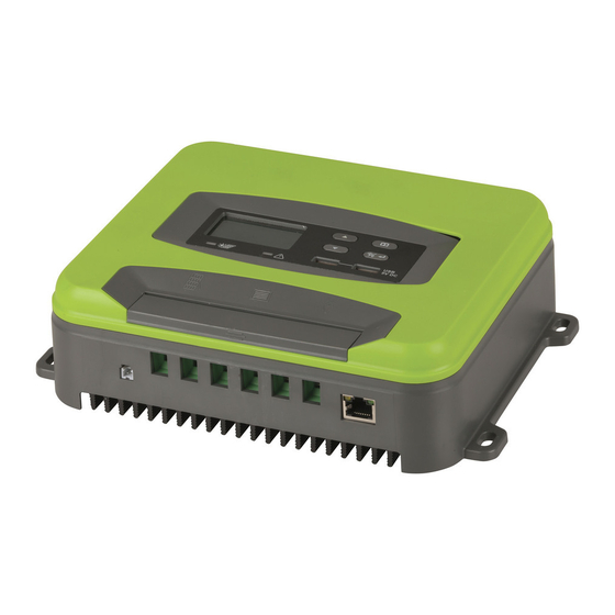
Product picture (Fig. 1) II. Functional description of each part of the panel (refer to Fig. 1 & 2): 1. UP (up button) 2. Down (down button) 3. MENU (main menu button) 4. Enter (OK button) 5. Green LED light (off when no charging, flashing during charging, stay on when fully charged). 6. Red LED light (Red LED light (off when no error , error alarm when the light is long on, lithium battery only has 12V gear, other gear flashing red light error) 7. 2*3A USB output 8. LCD screen Remark: (The operations of panel items 1‐4 are explained below). ... -
Page 5: Description Of Basic Functions 3
(Fig. 2) 9. External temperature probe 10. RJ45 port, connected to the remote control board through the network cable and synchronized with the LCD screen (this port is reserved and the remote control board is optional) 11. PV+ (connected to the positive electrode of the solar panel) 12. PV‐ (connected to the negative electrode of the solar panel) 13. B+ (connected to the positive electrode of the battery) 14. B‐ (connected to the negative electrode of the battery) 15. L+ (connected to the positive electrode of the load) 16. L‐ (connected to the negative electrode of the load) III. Description of basic functions PV (solar panel input): a. The maximum open circuit voltage of PV is 135V. b. PV integrates anti‐reverse (reverse connection alarm E8, no charging, please eliminate the fault). c. 12V battery, PV input voltage range is 16‐108V;24V battery, PV input voltage range is 32‐108V d. 36V battery, PV input voltage range is 48‐108V;48V battery, PV input voltage range is 64‐108V. Battery output function a. Identify 12//24/36/48V battery automatically; the maximum charging current is :12/24V/50A,36V/35A,48V/25A. b. Anti‐reverse connection (E1 alarm). Load output function (default OFF). a. Rated maximum output current 50A (12/24/36/48V). b. Overcurrent protection >55A. c. Short circuit protection (E4 alarm; please eliminate the fault). d. Load output over/undervoltage protection, recovery voltage; refer to the set voltage. ... - Page 6 a. Reduce load in case of over‐temperature: the charging current is always 28‐30A when the heat sink temperature ≥ 75°C. b. Recover when load is reduced: resume normal charging( 50A) when the heat sink temperature is <70°C. c. Stop charging when the heat sink temperature is ≥90°C; resume charging when the heat sink temperature is <60°C. External temperature compensation function (only for AGM/STD battery) a. 1. The system will automatically adjust the float voltage according to the ambient temperature. The external temperature probe is preferred. If the external temperature probe is not connected (or the external temperature is <40°C), use (temperature ≥ 20°C ‐ 5°C) by default. 2. The voltage may vary when the input energy is insufficient to stabilize the energy required for the float charging. b. For 12/24/36/48V batteries, when the external probe temperature ≤ 0°C ~40°C, the float charging voltage is 14.1/28.2V/42.3V/56.4V For 12/24/36/48V batteries, when the external probe temperature is 0°C~20°C, the float charging voltage is 13.8/27.6V/41.4V/55.2V For 12/24/36/48V batteries, when the external probe temperature ≥ 20°C, the float charging voltage is 13.5/27V/40.5V/54V. WIFI networking function a. The product may integrate WIFI module or not. b. If the product integrates a WIFI module, you can install the mobile APP, control the load switch through the APP and view the MPPT charger data in real time, such as battery voltage, charging current, etc. The LCD backlight is turned off if there is no button operation in 1 minute; any button operation will automatically activate the LCD backlight. a. USB battery input undervoltage/overvoltage protection (10.5V/60V), battery input undervoltage/overvoltage recovery (11V/59V); c. USB output 2*5V/3A. ...
-
Page 7: Description Of Lcd Screen 4
III. Description of LCD screen: A B C D E F G H I J K L M N O P A. Sun icon, displayed when solar panel is connected. ... - Page 8 O. Daytime and night icons; PV>12V, display daytime icon ; PV<12V, display night icon after 5 minutes. PV < 5V display night icon immediately . P. Numerical display (8888 characters). The current data of the machine can be switched by the MODE button, such as battery voltage / load voltage / PV voltage / time. IV. The operation of machine buttons is described below UP MENU ...
-
Page 9: Wire Diameter Requirements
when PV>10.5V, the output turns off after N minutes load delay, so the loop is repeated) (7. LD mode: The clock setting range is 0-12 hours. a. Clock 1 trigger condition: When PV<10V, clock 1 turns on the load for N minutes (clock 1 is set to 3 hours by default), and clock 2 executes following clock 1. -
Page 10: Electrical Parameters
VI. Electrical Parameters: PV input Parameters PV maximum open circuit voltage (VDC) 135V MPPT voltage (VDC) 16~108V Maximum PV input power (W) 12V battery≦700W; 24 battery≦ -48V 1500W; Maximum MPPT current (12/24V) /50A; 36V/35A;48V/25A DC output Battery voltage (VDC) 12//24/36/48V Battery capacity (AH) ≧50AH Output current (A) - Page 11 VII. Fault Codes reverse connec (please correct) open circuit prot ry not connected / or low voltage overcurrent prot on (circuit has constant current the machine may be damaged if there is an error) Load overcurrent /short circuit protec (error 10S, turn on the load elimina g the error)
Need help?
Do you have a question about the MP3745 and is the answer not in the manual?
Questions and answers