Advertisement
Table of Contents
- 1 Before You Begin
- 2 TV Hardware
- 3 EXTENDER Hardware
- 4 MOUNT Hardware
- 5 Weight / Screen Size Capacity
- 6 Attaching the Tv Plate to the Tv
- 7 Attaching the Wall Plate to the Wall
- 8 Wood Stud Installation
- 9 Concrete Wall Installation
- 10 Wall Installation
- 11 Concrete
- 12 Dual Stud
- 13 Position Arm on Wall Plate
- 14 Hang Your Tv
- Download this manual
Advertisement
Table of Contents

Related Manuals for Omnimount SC120FM


Summary of Contents for Omnimount SC120FM
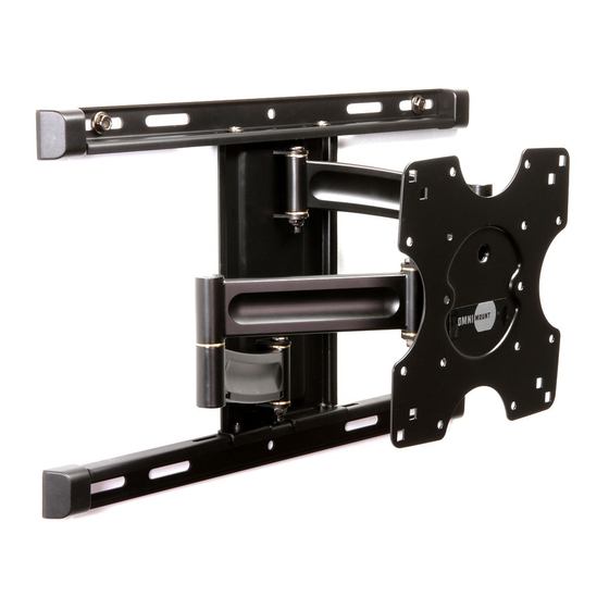
- Page 1 SC120FM Large Full Motion TV Wall Mount Max screen size: 42" - 80" (107-203 cm) Max weight 120 lbs (54.4 kg) CAUTION: DO NOT EXCEED MAXIMUM LISTED WEIGHT CAPACITY. SERIOUS INJURY OR PROPERTY DAMAGE MAY OCCUR! 777-61-062-G-02 rev F...
- Page 2 BEFORE YOU BEGIN Make sure you have power and signal outlets in the right spot. Now is a great time to check the length of your cables and make sure they will reach the appropriate outlets. Nothing’s worse than completing a perfect installation just to realize there’s nowhere to plug in the TV! Avoid TV glare.
- Page 3 TOOLS NEEDED 10mm 1/2" WOOD Ø 7/32" (5,5 mm) CONCRETE Ø 3/8" (9,5-10 mm) 777-61-062-G-02 rev F...
- Page 4 CONTENTS This product is designed to move easily when mounted to the wall and the weight of your TV is attached. Movements may be diffi cult before your TV is attached. Part # Description Wall Plate TV Plate VESA Extenders Cable Tie Wall Template Stud Finder/Level...
- Page 5 CONTENTS TV Hardware M8 x45mm M6/M8 x 10mm M6/M8 M6/M8 x 5mm M8 x30mm M6 x30mm M8 x15mm M6 x15mm EXTENDER Hardware M6 x 15mm MOUNT Hardware ST8 x 65mm M4 x 7mm M4/M5 777-61-062-G-02 rev F...
- Page 6 It is the responsibility of the installer to ensure all components are properly assembled and installed using the instructions provided. If you do not understand these instructions or have any questions or concerns, please contact customer service at 1-800-668-6848 or info@omnimount.com. Do not attempt to install or assemble this product if the product or hardware is damaged or missing.
- Page 7 WEIGHT / SCREEN SIZE CAPACITY 42"- 80" 120 lbs 54.4 kg USE WITH TVs LARGER THAN THE MAXIMUM WEIGHT AND/OR SCREEN SIZE MAY RESULT IN INSTABILITY CAUSING POSSIBLE INJURY. 777-61-062-G-02 rev F...
- Page 8 ATTACHING THE TV PLATE TO THE TV Using a Phillips screw driver attach the TV plate to the TV. Because this mount was designed to fi t a number of TV confi gurations, we’ve included a variety of screws and spacers. You will only be using 4 screws in this installation step. Spacers may be needed to accommodate TVs with a curved back, recessed mounting locations, or in the event that one of the TV rail obstructs the power or signal plug outlets.
- Page 9 NOTE: If the TV plate does not reach the mounting holes on the back of your TV, you will need to install the extenders. Please see the next page for the extender installation. ATTENTION: If your AV access is obstructed the fl at panel plate is designed for vertical adjustment with 100mm x 100mm hole patterns.
- Page 10 EXTENDER INSTALLATION These extenders will allow you to mount TV’s with up to a 600mm x 400mm hole pattern. Attach each extender to the TV plate using shown hardware. Once this step is complete, refer to the previous step for attaching the TV plate to the TV.
- Page 11 M8 x45mm M6/M8 x 10mm M6/M8 M6/M8 x 5mm M6 x30mm M8 x30mm M6 x15mm M8 x15mm 777-61-062-G-02 rev F...
- Page 12 ATTACHING THE WALL PLATE TO THE WALL This mount was designed to be used on two diff erent types of walls. One being a wood stud wall and the other being a solid concrete wall. Below is the pilot hole sizes for both types of walls. You’ll also notice this information printed on the WALL HARDWARE pack.
- Page 13 Dual Stud Concrete 777-61-062-G-02 rev F...
- Page 14 WALL INSTALLATION MOUNT Hardware Wood 1/2" ST8 x 65mm Concrete 1/2" ST8 x 65mm...
- Page 15 Dual Stud Concrete 777-61-062-G-02 rev F...
- Page 16 POSITION ARM ON WALL PLATE Choose one of the options for positioning your arm side-to-side.
- Page 17 Center Left Right 777-61-062-G-02 rev F...
- Page 18 HANG YOUR TV 1. We suggest having a friend help lift your TV and hang it on the wall plate. Please ensure that the puck on the back of the TV plate seats into the Wall/Arm Assembly. 2. Install the shown hardware on either side of the TV plate using a Phillips screwdriver to secure it to the Wall/Arm Assembly. M4 x 7mm M4/M5...
- Page 19 NOTE: For safe and proper installation be sure to install the locking /leveling screws as shown. Level monitor before securing screws. 777-61-062-G-02 rev F...
- Page 20 CABLE ROUTING Route your cables through the cable tie attached to the extension. Be careful of possible pinch points and feel free to use extra cable bundling or zip ties for a clean installation.
- Page 21 777-61-062-G-02 rev F...
- Page 22 TILT ADJUSTMENT Tilt your TV to the desired angle, then tighten the Tilt Adjustment Knob. Adjusting your TV’s tilt is a great way to avoid TV glare during certain times of the day.
- Page 23 ARM SWING ADJUSTMENT If the Arms are too easy or diffi cult to move in and out, adjust the friction at the pivot points. 10mm 777-61-062-G-02 rev F...
- Page 24 OmniMount bears no responsibility for incidental or consequential damages. This includes, but is not limited to, any labor charges for the repair of OmniMount products performed by anyone other than OmniMount. This warranty gives you specifi c legal rights, and you may also have other rights which vary from state to state. Specifi cations are subject to change without prior notice.
Need help?
Do you have a question about the SC120FM and is the answer not in the manual?
Questions and answers