Table of Contents
Advertisement
O TRO_ BILT
Operator's Manual
Rear-tine Tiller Models
630Cn
Tuffy_
634Fm
BroncoTM
634Bm
Super BroncoTM
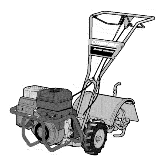
Model 634B Shown
IMPORTANT:
READ SAFETY RULES AND INSTRUCTIONS
CAREFULLY
WARNING:
This unit is equipped with an internal combustion engine and should not be used on or near any unimproved
forest-
covered, brush-covered
or grass-covered
land unless the engine's exhaust system is equipped with a spark arrester meeting applicable
local or state laws (if any). If a spark arrester is used, it should be maintained in effective working order by the operator. In the State of
California
the above is required by law (Section 4442 of the California
Public Resources
Code). Other states may have similar laws.
Federal laws apply on federal lands. A spark arrester for the muffler is available through your nearest engine authorized service dealer or
contact the service department,
P.O. Box 361131 Cleveland, Ohio 44136-0019.
TROY-BILT
LLC, P.O. BOX 361131 CLEVELAND,
OHIO 44136-0019
PRINTEDIN U.S.A.
FORM NO. 770-10594B
11/5/02
Advertisement
Table of Contents

Related Manuals for Troy-Bilt TUFFY 630CN


Summary of Contents for Troy-Bilt TUFFY 630CN
- Page 1 Federal laws apply on federal lands. A spark arrester for the muffler is available through your nearest engine authorized service dealer or contact the service department, P.O. Box 361131 Cleveland, Ohio 44136-0019. TROY-BILT LLC, P.O. BOX 361131 CLEVELAND, PRINTEDIN U.S.A.
- Page 2 Content Calling Customer Support ...2 Safety...3 Assembly...6 Freaturesand Controls ...10 Operation...12 Maintenance...17 Off-SeasonStorage...21 Troubleshooting...22 Parts List ...23 Warranty Information ...Back Cover This Operator's Manual is an important part of your new Rear-tine Tiller. It will help you assemble, prepareand maintain the unit for best performance.
- Page 3 SECTION 1: SAFETY This machinemeetsvoluntarysafetystan- dardB71.8-1996, whichis sponsored bythe OutdoorPowerEquipmentInstitute,Inc., and is publishedbythe AmericanNational StandardsInstitute. WARNING The engine exhaust from this productcontains chemicals known to the State of California to cause cancer, birth defects or other reproduc- SafetyAlert Symbol in this manual and on the unit to alert This is a safety alert symbol.
- Page 4 4. Exercise caution to avoid slipping or fall- ing. 5. If the unit should start to vibrate aonor- really,stop the enQne. disconnect the spark plug wire and prevent it from touch- ing the spark plug, and check immediately for the cause. Vibration is generally a warning of trouble.
- Page 5 Decals For your safety and the safety of others, vari- ous safety and operationa! decals are located on your unit (see Figure 1-2). Keepthe decals clean and legible at all times. Contactyour local service dealer or the factory for replacements if any decals are damagedor missing.
- Page 6 To protect your rights, put your claim in writing and mail a copy to the car- rier within 15 days after the unit has been delivered. Contact Troy-Bilt LLC it you need assistance in this matter. TOOLSMATERIALS NEEDED (11 3_8"open-end wrench- (2) 7/16"open-end wrench-...
- Page 7 Fig.2.2: Atlach handlebar ( 5.5 HpMOde! shown), 2. Removethe hairpin cotter (L, Fig. 2-3) and wheel drive pin (M) from the wheel hub (0) and wheel shaft (N). 3. Slidethe wheelfully inward on the wheel shaft (N, Fig. 2-3). Reinstall the wheel drive pin (M) through the wheel shaft only (not through the wheel hub).
- Page 8 The knob should return to its neutral posi- tion (resting against bracketL If it doesn't. contact your local dealer or Troy-Bilt LLC for technical assistance. Fig. 2-8: Install reverse cable bracketand reverseclutch cable, Fig, 2-9: Route reverseclutch cable (CC) as shown, Attach with cable tie (EE).
- Page 9 31bY I_: UI'IEUK LEVEL UI- Thetransmission was filled with gear oil at the factory. However,you should checkthe gear oil level at this time to makecertain it is correct. IMPORTANT: D o not operatethe tiller if the gear oil level is low. Doing so will result in severe damageto the transmission com- ponents.
- Page 10 SECTION 3: FEATURES A NDCONTROLS WARNING: Before operating your machine, carefully readand understand all safety, controls and operating instructions in this Manual, the separateEngine Owner's Manual,and on the decals on the machine. Failureto follow these instructions can result in serious personal injury. INTRODUCTION This Section describes the location and function of the controls on your tiller.
- Page 11 Figure 3-3: FREEWHEEL position. engine, be sure that both WARNING: Beforestarting wheels are in WHEELDRIVE position. See Whesl Drive Pins for instructions, Engaging the Forward Clutch Bail or ReverseClutch Control (if equipped) when the wheels are not inWHEELDRIVEcould allow the tines to rapidly propel the tiller forward or backward.
- Page 12 SECTION 4: OPERATION WARNING: Before operating your machine, carefully readand understand all safety (Section 1), controls (Section 3) and operating instructions (Section 4) in this Manual, the separate Engine Owner's Manual,and on the decals on the machine. Failureto follow these instructions can result in serious personal injury.
- Page 13 KEEP A WAY F_OMROTATING 11NES. ROTATING 11NE$ W ILLCAUSE INJURY. Stoppingthe Engineand Tiller 1. Tostop the wheels and tines, releasethe Forward Clutch Bail (all models) or the Re- verse Clutch Control (Models 634F and 634B) -- whichever control is in use. 2.
- Page 14 TILLING Tilling Depths _=i, WARNING: Before A L • tilling, Contactyour telephone or utilities company and inquire if underground equipment or lines are used on your property. Do not till near buried electric cables, telephone lines, pipes or hoses. • Whencultivating (breakingup surfacesoil around plantsto destroyweeds,seeFig.4-9), adjust thetinesto dig only 1"to 2"deep• Using shallowtilling depthshelpspreventinjury to plantswhose rootsoften grow closeto the surface.
- Page 15 TILLING PowerComposting Powercomposting simply meanstillingunderand burying in thesoil all mannerof organic mattersuch as crop residues,leaves,grassclippings and cover crops. This materialwill de- composeduring the non-growingseasonand add important n aturalnutrientsto the SO Thefirst placeto beginis with crop residuessuch asleftovervines,stalks,stemsand roots, Powercompost these crop residuesas soon asthey finish bearing.Thesoonerthis isdone, the better,astendergreen matter is easierto till under.
- Page 16 TILLING TerraceGardening(continued) • Tocreatea terrace,startat the top of the slopeand work down.Go backand forth acrossthe first r0was shown in Fig.4-!0. • Eachsucceedinglowerterraceisstartedbywalkingbelowtheterraceyou'repre- paring. Foraddedstability of thetiller, alwayskeepthe uphill wheelin the soft, new- ly tilled soil. Do not till the last 12"or more of the downhill outside edge of each terrace.
- Page 17 SECTION 5: MAINTENANCE WARNING: Before inspecting, cleamng or serwcmg the machine, shut off engine. wait for all moving parts to come to a complete stop, disconnect spark plug wire and move wire away from spark plug. Remove ignition keyon electric start models.
- Page 18 WARNING: moving parts to come to a complete stop, disconnect spark plugwire and move wire away from spark plug. Failureto follow these instructions can result in serious personal injury or property damage. 4. The gear oil level is correct if the gear oil is approximately halfway up the side of the main drive shaft.
- Page 19 WARNING: moving parts to come to a complete stop, disconnect spark plugwire and move wire away from spark plug. Failureto follow these instructions can result in serious personal injury or property damage. Figure 5-3: Installtinessothatcutting edgenf tinesentersoilfirstwhen tillermoves forward, CHECKING ANDADJUSTING FORWARD DRIVEBELTTENSION It is important to maintain correct tension on the forward drive belt.
- Page 20 (see Check- ing and Adjusting Forward Drive Belt Ten- sion). If this fails to correct the problem, contact Troy-Bilt LLC or your authorized dealer for service advice. CHECKING ANDADJUSTING RE- VERSEDRIVEBELTTENSION...
- Page 21 WARNING: moving parts to come to a complete stop, disconnect spark plugwire and move wire away from spark plug. Failureto follow these instructions can result in serious personal injury or property damage. 3. Cleanaround the oil dipstick or oil fill tube (whichever applies) to prevent dirt from falling into the crankcase.
- Page 22 WARNING: moving parts to come to a complete stop, disconnect spark plugwire and move wire away from spark plug. Failureto follow these instructions can result in serious personal injury or property damage. PROBLEM Enginedoes notstart Spark plug w_remsconnec_eo Engine Throttle Control Lever incorrechl set Fueitank emp[y.
- Page 23 SECTION 6: MODELS 630C,634F & 634B PARTS LIST PARTNO. 1185469 SpirolPin 710-0597 HexHd. Screw,1/4-20x 1 710-0599 Screw,Self-Tapping,I/4-20 x 1/2 710-0874 HexHd. Screw, 5 /16-18x 1-1/4 710-3039 HexHd.Screw,5/16-18x 1/2 712-0291 HexLockNut,1/4-20 712-3004A HexFlange LockNut,5/16-18 712-3009 HexNut,5/16-18 736-0119 LockWasher,5/16 GW-55013-1 HoodBracket, L eft Hand GW-55013-2 HoodBracket, R ightHand _ _"...
- Page 24 MODELS 630C, 634F & 634B 18 \...
- Page 25 PARTNO. 1918749 Bumper(C) 710-3073 HexScrew, 5 /16-18x2-1/4(C) 712-0267 Nut,Hex,5/16-18(C) 736-0119 LockWasher,5/16(C) (A) ForModel630C (B) ForModel634F (C)ForModel634B PARTNO. DESCRIPTION 1916719 Cable Assembly, ReverseClutch(B) (C) 1916755 Upper Handlebar 1917479 Bail, ForwardClutch 1918745 Cable Assembly, ForwardClutch 710-0599 Screw, Self-Tapping,I/4-20 x 1/2 710-3008 Screw, Hex,5/16-18 x 3/4 712-3009 HexLock Nut, 5/16-18 GW-55042...
- Page 26 MODELS 630C, 634F & 634B (A) ForModel6300 (B) ForModel634F (C)ForModel6348 * Useas required to obtainbetween .005"and .015"allowable end-play. 4 _\ PARTNO. DESCRIPTION GW-9517 SnapRing GW-1714 Bearing, Tapered Roller(with race) GW-50043 SupportWasher, R ear 1904277 Drive Shaft(A) (B) (C) GW-1224-1" Shim,RearBearing Cap,.010"thick GW-1224-2"...
- Page 27 FRONT (A) ForModel6300 (B) ForModel634F (C)ForModel6348 * Useas required to obtainbetween .005"and .030"allowable end-play. PARTNO. DESCRIPTION GW-9512 Retainer, SnapRing,"E" Type 1909950 Retainer, SnapRing GW-1166-1" Shim,0.062"thick GW-1166-2" Shim,0.030"thick GW-1166-3" Shim,0.015"thick GW-1166-4" Shim,0.010"thick GW-1166-5" Shim,0.005"thick GW-1086 Bronze Bushing 1916741 Wheel S haft(B) (C) GW-55004 Wheel S haft(A) GW-9305...
- Page 28 MODELS 630C, 634F & 634B PARTNO. GW-9727 Plug,Transmission O il Fill 710-04049 HexHd. Flange Screw,5/16-18x 5/8,G r. 5 736-0119 LockWasher,5/16 1918377 RearCover, T ransmission 1916641 FrontCover,Transmission GW-50032 Gasket, H ousing Cover GW-9617 OilSeal,DriveShaft * included with transmission when purchased as an assembly only, Remove and discard when installing the transmission on tiller.
- Page 29 Hold Tines With Blunt EndToward You LEFT-HAND TINE RIGHT-HAND T INE NOTE:Ideotib Left and Right sides of tiller bj standing _n operator position and facing direction of forward travel. 1"Usedon Leftsideoftiller :j:Usedon Rightsideof tiller PARTNO. 710-3005 HexHd. Screw,3/8-16 x 1-1/4, Grade5 GW-50049-01 Single Bolo Tine - Right Handt (A) (B) (C) 712-3000...
- Page 30 MODELS 630C, 634F & 634B...
- Page 31 PARTNO. 1107382 Flat W asher,5/16 1108841 Key, 3 /16"x 1-1/2"(B (C) 1916531 Pulley, E ngine Drive(8) (C) GW-55035 Pulley, E ngine Drive(A) 1916532 Transmission Pulley(B) (C) GW-55031 Transmission Pulley 1916535 Pulley, R everse Idler(B) (C) 1916652 Guard,Belts/Pulleys 1916657 Forward DriveBelt(B) (C) GW-55037 Forward DriveBelt(A) 1916658...
- Page 32 All Troy-Bilt branded rear tine walk-behind tillers with gear drive transmissions. ISCOVERED This warranty begins on the date of purchase and is warranted by Troy-Bilt LLC for the life of the tiller, to the odgina[ purchaser only. WHAT IS COVERED...
Need help?
Do you have a question about the TUFFY 630CN and is the answer not in the manual?
Questions and answers