Table of Contents
Advertisement
Advertisement
Table of Contents

Related Manuals for Huvitz HLM-7000


Summary of Contents for Huvitz HLM-7000
- Page 2 Auto Lensmeter HLM-7000 Service Manual Auto Lensmeter HLM-7000...
-
Page 3: Table Of Contents
INDEX INTRODUCTION ................4 1.1......................... 4 OMPONENTS 1.2........................6 EPAIR ROCEDURE 1.3............................7 AUTIONS 1.4......................... 7 OFTWARE VERSION 1.5........................... 7 PTICAL YSTEM 1.6......................9 EASUREMENT RINCIPLE CHECKING AND SETUP METHOD ..........10 2.1..........................10 ETUP RDER 2.2. - Page 4 Auto Lensmeter HLM-7000 3.8.................... 47 EMOVING AIN BOARD ASSEMBLY 3.9. R ....................49 EMOVING ACK BONE ASSEMBLY 3.9.1............ 51 EMOVING ENS HOUSING BONE AND SUBASSEMBLY 3.9.2. CCD C ..................53 EMOVING AMERA ASSEMBLY 3.10. SMPS A ........... 55...
-
Page 5: Introduction
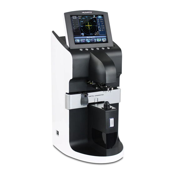
1. Introduction 1.1. Components List LCD Display Key Button Marker Lever PD Sensor Lens Table Lens Holder Table Lever Lens Supporter Memory Button Printer Cover UV Cover Figure 1. Components Names (I) - Page 6 Auto Lensmeter HLM-7000 Power Switch Figure 2. Components Names (II) Power Connector Foot Switch Connector Figure 3. Components Names (III)
-
Page 7: Repair Procedure
1.2. Repair Procedure Power ON 1. Examining the Internal Components First 2. Inspecting The value, S.C.A. Prism Normal State Checking Abnormal State Cleaning the Pinhole Power off and on Normal State Checking Abnormal State Setup Again Exit Figure 4. Repair procedure flow chart... -
Page 8: Cautions
Auto Lensmeter HLM-7000 Cautions 1.3. Always protect this instrument with Dust Cover after using. Do not vibrate or drop this instrument; it can cause damage. Use soft cloth or cotton swaps with alcohol when clean the 4 pinhole. Software OS version 1.4. - Page 9 light except the light source : micro lens array. Focus the every spot. Receiving Light Part 2-dimentional CMOS sensor : converts signals into digital value. Emitting light part and receiving light part also built optical system for UV measurement. One is composed of UV lamp and the other receives UV light. The wavelength of the UV light is 395nm.
-
Page 10: Measurement Principle
Auto Lensmeter HLM-7000 Measurement 1.6. Principle Basic Principle When there is no lens (0D state), parallel light that has transmitted the collimator lens passes the pinhole and makes image on CCD. In case of convex lens (lens with plus diopter), parallel light that has transmitted the collimator lens converges through the measuring lens, passes the pinhole and then makes image on CCD. -
Page 11: Checking And Setup Method
When you turn on the power switch, you should hear the beep sound and see the ROM information. At this point, press the two buttons together in the third button and sixth button. Then, after the beep sound, your lensmeter, HLM-7000 will start in setup and check mode. While this mode, ‘SETUP’ and ‘Temperature’ mark will flicker in the left-upper area of the centric circles. -
Page 12: How To Set Origin
Auto Lensmeter HLM-7000 2.2. How to Set Origin The steps of setting origin are as follows: A. Press the ‘LENS SETUP’( ) button. Press the ‘MEASU’ button. C. Determine the lens to measure by using two ‘-INDEX’, ’+INDEX’ buttons in the left side. -
Page 13: How To Set 12 Standard Lenses
2.3. How to Set 12 standard lenses If the measured value is not accurate, you should set the diopter variables again by using the standard lens-set: for all the 12 lenses in the standard lens set. Always keep the standard lens clean out of dust or stain. A. -
Page 14: How To Set Prism
Auto Lensmeter HLM-7000 2.4. How to Set Prism If the measured value is not accurate, you should set the 2Δ, 5Δ, 10Δ lens again by using the standard lens-set. A. First, convert prism display format into P-B. Then, press the ‘0D PRISM’ ( ) button. - Page 15 ‘Prism Setup’ screen will show the following information: PRISM : 2 Prism, 5 Prism, 10 Prism : Display prism index currently. ANGLE : Display axis index currently. Angle Prism Base 0° ~ 45° center 46° ~ 90° center 91° ~ 135° center 136°...
-
Page 16: How To Set Diopter Prism
Auto Lensmeter HLM-7000 2.5. How to Set Diopter Prism If the measured value is not accurate, you should set the -10D, -15D, -20D, -25D, +10D, +15D, +20D, +25D lens again by using the standard lens-set. A. First, convert prism display format into P-B. - Page 17 -10D, -15D, -20D, -25D, +10D (LOW PRISM : 3prism below / HIGH PRISM : 3prism over) +15D, +20D, +25D (LOW PRISM : 5prism below / HIGH PRISM : 5prism over) but, LOW PRISM = step D and HIGH PRISM = step G. ‘Diopter Prism Setup’...
-
Page 18: The Calibration Of The Cylindrical Axis
Auto Lensmeter HLM-7000 2.6. The calibration of the cylindrical axis With the +5D rectangular cylindrical lens, we can calibrate the cylindrical axis of our machine. The procedures are as followings: A. T hen, press the ‘CYL SETUP’ ( ) button. -
Page 19: The To Set Pd
2.7. The to set PD With the PD Sensor, we can calibrate the PD value of our machine. The procedures are as followings: A. Press the ‘PD&UV’( ) button. Push in the PD sensor is the leftmost. And press the ‘L Lim’ button. C. -
Page 20: The To Set Uv
Auto Lensmeter HLM-7000 2.8. The to set UV With the UV, we can calibrate the UV value of our machine. The procedures are as followings: A. Press the ‘PD&UV’( ) button. Press the ‘UV’ button in right end. C. Open UV cover. -
Page 21: Diopter Setting Variables List
2.9. Diopter Setting Variables List The followings are diopter setting variables list: DISP SCREEN INFORMATION CEN : (+398.0612, +239.63) : center of the four points in 0D state. 0th: L=236.15 ; 1.00, 1.00, 1.00, 1.00 : average distance and distance rates between the four points and -25D -25D 1th: L=223.50 ;... -
Page 22: How To Change The Ccd Camera
Auto Lensmeter HLM-7000 2.10. How to change the CCD camera Pinhole Housing Upper Holes Socket Set Screws Base Hole The procedures for changing a camera are as followings. A. Remove all subassemblies that are the side cover, the lens table and the lower cover and the CCD cover etc. - Page 23 continuously. We should place the CMOS Camera keeping two conditions: The first condition is the position of center point. The center position is shown at the row like this. - CEN : (+640.00, +512.00) It must be within ( +640.00 ± 10, 512 ± 10 ) The second one is the orientation of CMOS Camera.
- Page 24 Auto Lensmeter HLM-7000 A12: Angle of two point Center Point...
-
Page 25: How To Change The Led Assembly
2.11. How to change the LED Assembly The spare part for the LED assembly is the Upper Frame. So, we provide all upper frame assembly for the LED assembly. The procedures for changing the upper frame Assembly are as followings: B. -
Page 26: How To Change The Pinhole Housing
Auto Lensmeter HLM-7000 2.12. How to change the Pinhole Housing Pinhole Housing Upper Holes Socket Set Screws Base Hole The procedures for changing the Pinhole Housing are as followings: A. Take out the Lens Supporter. B. Remove the Pinhole Housing Cover which is the below cover under the Lens Supporter. -
Page 27: Repair Standard
3. Repair Standard 3.1. Removing cover assembly... - Page 28 Auto Lensmeter HLM-7000 Component Removal method - First, extract [1] using the sharp thing. Cover PD Bar Handle Cap Cover PD Bar Handle - Next, remove three screws from [2] and separate [2] Cover White Front Cover Right - Next, remove nine screws that is located on the bottom...
-
Page 29: Disassembling Lcd Ass'y
3.2. Disassembling LCD ass’y... - Page 30 Auto Lensmeter HLM-7000 Component Removal method - First, remove four screws that fix [1] and separate it. Cover LCD Back Cover LCD Front - Next, remove four screws that fix [2] and separate it. LCD Window LCD Monitor Bracket - Next, remove four screws that fix [4] and [5].
-
Page 31: Removing Printer Ass'y
3.3. Removing Printer ass’y... - Page 32 Auto Lensmeter HLM-7000 Component Removal method - First, remove four screws that fix ‘APS Print Assy’ from the PR Body ‘Cover Right’. Thermal Printer B/D Then, separate it from the ‘Cover Right’ PR Open Cover PR Open Cover Holder - Next, disconnect [6]’s flat cable from [2].
-
Page 33: Removing Pd Assembly
3.4. Removing PD assembly... - Page 34 Auto Lensmeter HLM-7000 Component Removal method - Disconnect ‘PD Bar Board’ cable from ‘Main Board’. PD Bar Assembly O-Ring & Washer - Then, remove two screws that fix [4] from the [1]. Filter Housing Cap Then, separate it. Nose Assembly PD Bar Cover - To separate [2], remove one screw that is fixed to the ‘PD...
-
Page 35: Removing Pd-Bar Subassembly
3.4.1. Removing PD-Bar subassembly... - Page 36 Auto Lensmeter HLM-7000 Component Removal method - To separate the ‘Nose Assembly([3]~[7])’, remove two PD Bar Plate screws that fix [8]. PD Bar Cover Then, separate ‘Nose Assembly’. PD Nose Brk Nose Shaft - Then, remove four screws that fix [2] and take off [2].
-
Page 37: Removing Uv Assembly
3.5. Removing UV assembly... - Page 38 Auto Lensmeter HLM-7000 Component Removal method - First, remove four screws that fix [1] from the UV Frame Support Brk ‘Main Frame Assy” UV Bone Then separate it. UV LED PCB UV Teflon (Upper) - After remove four screws that fix [2]~[6], then separate UV REC PCB from [1].
-
Page 39: Removing Movement Assembly
3.6. Removing Movement assembly... - Page 40 Auto Lensmeter HLM-7000 Component Removal method - To separate [1], remove four screws that fix [2]. Movement Left Assembly Shaft Fix Brk - To separate [3], remove three screws that fix [3] Movement Right Assembly - Assembly is the reverse procedure of disassembly.
-
Page 42: Removing Movement(Left) Subassembly
Auto Lensmeter HLM-7000 3.6.1. Removing Movement(Left) Subassembly... - Page 43 Component Removal method - Remove four screws to separate [1]’s sub assembly. Foot Frame Brk F T2 Control Pos Pin - Unscrew [2] by using the spanner. Foot Moving Block Guide Shaft 4 - Remove two screws to separate [7]~[10]’s sub Teflon Washer assembly.
-
Page 44: Removing Movement(Right) Subassembly
Auto Lensmeter HLM-7000 3.6.2. Removing Movement(Right) Subassembly... - Page 45 Component Removal method - First, remove two screws that fix [8]~[15]’s sub Pen Slide Base assembly. Slide Moving Block Slide Fix Block - Remove two screws to separate [9]~[15]. Slide Shaft Bearing Ball (Ø3) - Remove the ‘E-ring’ to separate [12]. Slide Guider And then separate [9], [10],[12], [13] and ‘Pen Pen Extension Spring...
-
Page 46: Removing Gear Assembly
Auto Lensmeter HLM-7000 3.7. Removing Gear assembly... - Page 47 Component Removal method - Remove three screws to separate the ‘Gear Assembly’ PD Pinion Brk from the ‘Back bone Assembly’ PD Pinion Shaft Holder And then separate it. PD Pinion Nut Wave Washer - Unscrew two set-screws that fix [2], and then separate Gear Washer [2].
-
Page 48: Removing Main Board Assembly
Auto Lensmeter HLM-7000 3.8. Removing Main board assembly... - Page 49 Component Removal method - Remove four screws that fix [2], and then separate [2]. Main BD Bracket HLM Main Board - Remove two screw that fix to ‘Cover Top 1’ - Remove two screw that fix ‘PCB Supports’ - Remove two screw that fix [1]. - And then, separate [1].
-
Page 50: Removing Back Bone Assembly
Auto Lensmeter HLM-7000 3.9. Removing Back bone assembly... - Page 51 Component Removal method - Remove four wrench Bolts that fix [1]. Back bone Assy - And then, separate it. - Assembly is the reverse procedure of disassembly.
-
Page 52: Removing Lens Housing Bone And Led Subassembly
Auto Lensmeter HLM-7000 3.9.1. Removing Lens housing bone and LED subassembly... - Page 53 Component Removal method - Remove four wrench bolts to separate ‘Lens housing LED Bone bone Assembly’ form the ‘back Bone Assembly’ LM Lens LED Lens Nut - Unscrew [3], and then separate [3], [2] in order. LED Housing - Unscrew three set-screws to separate ‘LED LED Diaphragm Subassembly([4]~[9])’...
-
Page 54: Removing Ccd Camera Assembly
Auto Lensmeter HLM-7000 3.9.2. Removing CCD Camera assembly... - Page 55 Component Removal method - Remove four screws to separate [2]~[4]assembly. Back Bone Then separate it. Filter Housing MM Lens Array - Remove four screws that fix [7] and then separate it.. 4 Pin Hole CMOS Sensor B/D - To separate [5] from [1], remove four screws that fix CCD Camera Interface B/D [5].
-
Page 56: Removing Smps Assembly And Power S/Wand Fuse Inlet
Auto Lensmeter HLM-7000 3.10. Removing SMPS Assembly and Power S/W and Fuse Inlet... - Page 57 Component Removal method - Remove two screws that fix [2], then separate it from Base Frame [1]. SMPS Fuse Inlet - Pull out [3], [4] from [1]. Power S/W Foot S/W - Remove two screw that fix [5]. RS232c And then, separate it. Foot - Remove two PCB Supports from [6].
-
Page 58: Electrical System
Auto Lensmeter HLM-7000 4. Electrical System 4.1. MAIN BOARD PCB ASS’Y [BT1] SW1: [CN12] [CN5] Lithum-Ion Battery Op Mode Selection Key Pad QVGA TFT LCD For Calendar [CN19] SVGA [CN4] LCD Connector RS-232 For Mfg. [CN1] Rom Socket [CN13] Optic LED1... -
Page 59: Electrical Block Diagram
Electrical block diagram... -
Page 60: Inspecting Smps
Auto Lensmeter HLM-7000 4.3. Inspecting SMPS Check1 . Check if POWER SWITCH and RUG is connected properly. Check2 . Check FUSE in POWER SOCKET with DMM. Check1 . Is Power LED on in SMPS MODULE? Check2 . Check the voltage of DC POWER Cable with DMM. -
Page 61: Lcd Test
4.3. LCD TEST Measurement screen is not displayed… Check1 . SMPS TEST Check1. LCD is bright but there is no character Check if CN5 connector of LCD is or figure. connected correctly to MAIN Check2 . There are horizontal lines on LCD and BOARD. -
Page 62: Led Test
Auto Lensmeter HLM-7000 4.4. LED TEST Cross mark (+) isn’t displayed in measurement waiting state… Check1 . Place white paper on FILTER COVER and Change LED module check if circular red right comes out from it. Check1 . Change MAIN BOARD PCB ASS’Y and test again. -
Page 63: Uv Module Test
4.5. UV MODULE TEST I cannot get UV-LED value… Check1 . Check if violet light radiated from OPTIC LED Change UV-LED PCB ASS’Y comes out from UV measurement part. UV-LED value in UV mode is 0%. Check1 . Check if UV SENSER in UV measurement part is hidden by obstacles such as FILTER COVER . -
Page 64: Pd Test
Auto Lensmeter HLM-7000 4.6. PD TEST PD value is not displayed… Check1 . Check right/left switching when you move LEVER Change MAIN right and left compared to the center of PD. Change PD MODULE... -
Page 65: Thermal Printer Test
4.7. THERMAL PRINTER TEST “PRT: HEAD UP” message is displayed on LCD… Check1. Open PRINTER COVER and check if HEADER LEVER towards upside. “PRT: PP EMPTY” message is displayed on LCD when pressing PRINTER BUTTON… Check1. Open PRINTER COVER. Check2. Check PRINTER PAPER tray. -
Page 66: How To Upgrade The Os Program
5.1. Introduction Downloading program for HLM-7000 with RS232 cable (Lensmeter RS232) provides downloading function of the firmware software from PC to Lensmeter, HLM-7000 with serial cable. An administrator of the Lensmeter hardware can receive the Firmware by e-mail or else and load it to his/her lensmeter by this downloading program when the new upgrade version of firmware comes out. -
Page 67: How To Upgrade The Os Program Using Dnw Application In Hlm Machines
5.2. How to upgrade the OS program using DNW application in HLM Machines A. Copy the DNW application files. DNW consists of two files : the executable file(= dnw.exe), the configuration file(= dnw.ini ). It is no need to install it in your desktop computer. - Page 68 Auto Lensmeter HLM-7000 Connect Serial Port D. Click the item in the menu to open the specified serial port. After succeeding in opening the serial port, the title of DWN application shows the Com port and the Baud Rate on the title bar.
- Page 69 H. After finishing the procedure 9, you’ll see some information on the terminal and finally you can see the screen as following : Finally turn off and on the machine.
Need help?
Do you have a question about the HLM-7000 and is the answer not in the manual?
Questions and answers