Table of Contents
Advertisement
Quick Links
Advertisement
Table of Contents

Related Manuals for EZ-ACCESS Modular Ramp


Summary of Contents for EZ-ACCESS Modular Ramp
- Page 1 Modular Ramp Assembly Manual ...
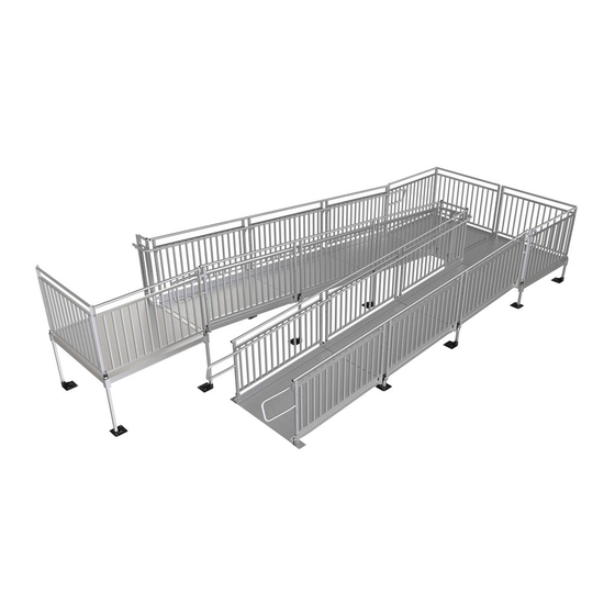
- Page 2 ASSEMBLY MANUAL ® For EZ-ACCESS Modular Ramp Systems ATTENTION INSTALLER: For residential use only! 850 lb. weight capacity Read all instructions, including ‘PERIODIC MAINTENANCE AND SAFETY,' prior to ramp assembly Please leave this ASSEMBLY MANUAL with the end user ATTENTION END USER: ...
-
Page 3: Table Of Contents
CONTENTS SECTION 1: BASIC SYSTEM COMPONENTS IDENTIFYING COMPONENTS ..................4-6 SECTION 2: PLATFORMS INSTALL PLATFORMS ....................... 7 INSTALL SUPPORT TUBES AND FEET AND ADJUST PLATFORM HEIGHT....8-9 CONNECT TWO PLATFORMS TOGETHER ............... 10-11 INSTALL UNIVERSAL ANGLE BRACE ................12 INSTALL UNIVERSAL CROSS BRACE ................ -
Page 4: Section 1: Basic System Components
1. BASIC SYSTEM COMPONENTS 1.1. Because each ramp configuration will differ from one another, your system may or may not contain all these basic system components. MODULAR RAMP WITH HANDRAIL MODULAR RAMP WITHOUT HANDRAILS MRLT – RAMP LOWER TRANSITION MRRC – CONNECTOR – RAMP TO RAMP... - Page 5 UNIVERSAL PLATFORM (STRAIGHT CONFIGURATION) UNIVERSAL PLATFORM (TURN CONFIGURATION) MPPC – CONNECTOR – PLATFORM TO PLATFORM MHRRRC – CONNECTOR – RAMP HR TO RAMP HR MHRPRC – CONNECTOR – PLATFORM HR TO RAMP HR MBP36, MBP48, MBP60 - BRIDGE PLATE MSTSXXPR - FEET & SUPPORT TUBE PAIRS MHREC - HANDRAIL END CAP XX DENOTES USABLE LENGTH (LENGTHS AVAILABLE 10”...
- Page 6 MUAB – UNIVERSAL ANGLE BRACE MUCB5 & MUCB5 – UNIVERSAL CROSS BRACE NOTE: MUCB5 USED UP TO 5’ PLATFORM SIDE & MUCB7 USED OVER 5’ PLATFORM SIDE MUG36 – MODULAR GATE 36” MTDK – TIE DOWN KIT MPTS – PLATFORM TIE STRAP MRHP - RAMP HANGER PAIR MRGT –...
-
Page 7: Section 2: Platforms
2. PLATFORMS 2.1. INSTALL PLATFORMS: If your system does not include a platform, skip to ‘CONNECT RAMP SECTIONS’ of this instruction guide. It is strongly suggested that all platforms and ramps be installed before installing handrails (see ‘HANDRAILS’). 2.1.1. There are three types of platforms (one or more of these platform arrangements may be used in an installation). -
Page 8: Install Support Tubes And Feet And Adjust Platform Height
2.2. INSTALL SUPPORT TUBES AND FEET AND ADJUST PLATFORM HEIGHT: 2.2.1. Support tubes, plugs & feet come in pairs. Support tubes will come in lengths sufficient for the heights at specific locations and should not need to be cut. It is recommended that the plug be installed in the support tube before installing the tube into the platform, but it can be done at any point during the installation. - Page 9 2.2.5. Lift each corner of the platform and install a base foot on each support tube oriented so that the foot extends under the platform as shown in FIG. 2.4. Make sure the feet are fully engaged on the tubes and tighten the thumb screw on each foot securely.
-
Page 10: Connect Two Platforms Together
2.3. CONNECT TWO PLATFORMS TOGETHER: 2.3.1. Assemble the first platform as described in the previous steps except on the side where the second platform will connect, install two MPPC (CONNECTOR – PLATFORM TO PLATFORM) before installing feet onto the support tubes. Make sure the platform connector set screws are oriented outward so they will be accessible. - Page 11 FIG. 2.6 - 11 -...
-
Page 12: Install Universal Angle Brace
2.4. INSTALL UNIVERSAL ANGLE BRACE: 2.4.1. For added stability, any platform with a walking surface over 36″ high requires bracing. The MUAB (UNIVERSAL ANGLE BRACE) is used for surfaces 36″ up to 72″. Walking surfaces 72″ and higher require cross braces in addition to the angle braces. -
Page 13: Section 3: Ramps
3. RAMPS 3.1. CONNECT RAMP SECTIONS: 3.1.1. Place the walking surface side of the ramp sections face down, onto cardboard or lawn so that the ramp is not damaged (scratched or dented). NOTE: If you are installing a single ramp section, skip to 'INSTALL A SINGLE RAMP RUN TO AN EXISTING STRUCTURE.’... -
Page 14: Install Ramps On Platforms
3.2. INSTALL RAMPS ON PLATFORMS: 3.2.1. The following will address attaching a ramp or ramp run to a platform. If the ramp needs to be angled with respect to the platform or is going to be attached to an existing porch, skip to ‘ANGLING RAMPS WITH RESPECT TO PLATFORMS’. -
Page 15: Attach Support Legs To Ramps
3.3. ATTACH SUPPORT LEGS TO RAMPS: 3.3.1. Attach support tube bracket which are included in the MRRC (CONNECTOR – RAMP TO RAMP) to the center saddle bracket (previously installed) using 3/8″ nylon insert lock nuts and 3/8″ washers (FIG. 3.5). 3.3.2. - Page 16 FIG. 3.7 FIG. 3.8 3.3.7. If the ramp walking surface is over 36″ high, an MUAB (UNIVERSAL ANGLE BRACE) must be installed under the ramp (FIG. 3.9). Where two ramps are joined together, use one brace band on 3.3.7.1. each support tube to secure the ends of the angle brace nearest the twist using a 5/16″...
-
Page 17: Install Ground Transition Ramp
3.4. INSTALL GROUND TRANSITION RAMP: 3.4.1. The MRGT (RAMP GROUND TRANSITION) consists of two sections that need to be connected together, then installed into ramp. IMPORTANT: The ground transition is only designed to transition from the lowest ramp in the run to the ground and should not be used in any other location. - Page 18 FIG. 3.12 FIG. 3.13 3.4.6. Install protective caps over side rail corners (FIG. 3.14) by placing one cap on each side at both the top and bottom of the ramp. If necessary, use silicone adhesive to bond the cap to the ramp. FIG.
-
Page 19: Install A Single Ramp Run To An Existing Structure
3.5. INSTALL A SINGLE RAMP RUN TO AN EXISTING STRUCTURE: 3.5.1. Turn the ramp section upside down on a flat surface. Do this on cardboard or a lawn so that the ramp is not damaged (scratched or dented). 3.5.2. Locate MRHBPR (RAMP HANDRAIL END BRACKET PAIR). Install four end brackets (will be used to attach handrails in a later step). -
Page 20: Anchor Ramp Upper Transition
ANCHOR RAMP UPPER TRANSITION: The MRUT (RAMP UPPER TRANSITION) 3.6. must be anchored to a substantial surface. Use the pre-drilled holes at each corner of the upper transition as guides. 3.6.1. IF RESTING ON A WOODEN SURFACE: 3.6.1.1. Secure upper transtiion by installing the 1/4″ self-drilling stainless steel screw through each hole (FIG. -
Page 21: Angle Ramps With Respect To Platforms, Porches, Or Decks
3.7. ANGLE RAMPS WITH RESPECT TO PLATFORMS, PORCHS, OR DECKS: 3.7.1. There are situations where it is necessary to angle ramps with respect to a platform, porch or deck. This can be done relatively easily, but the components required are not normally included with a typical system unless it is a ramp or ramp run without a platform. -
Page 22: Section 4: Handrails
4. HANDRAILS 4.1. PRE-ASSEMBLE HANDRAILS: 4.1.1. One pair of handrails is required for each ramp section. Handrails are interchangeable. 4.1.2. In a multiple ramp run configuration, handrail connectors (MRRC – CONNECTOR RAMP TO RAMP) are used to join handrails together. Refer to FIG. -
Page 23: Install Ramp Handrails
4.2. INSTALL RAMP HANDRAILS: 4.2.1. Install pre-assembled handrail section to side of ramp run (FIG. 4.2). The vertical posts of the handrails each have two holes that 4.2.1.1. correspond with the studs on handrail ends brackets (installed in previous steps). 4.2.1.2. -
Page 24: Install Platform Handrails
4.3. INSTALL PLATFORM HANDRAILS: 4.3.1. Depending on your configuration, refer to FIG. 4.4 and FIG. 4.5, as needed. 4.3.2. Pre-assemble the platform handrails by inserting the #10-24 hex washer head thread cutting screws through the angle post, and into the screw slots inside the handrail tubes and curb, then and tighten securely (FIG. - Page 25 FIG. 4.4 FIG. 4.5 - 25 -...
-
Page 26: Install Handrail End Loops
4.4. INSTALL HANDRAIL END LOOPS: 4.4.1. Locate MRHRL (HANDRAIL END LOOP SINGLE). Install 4″ ring joiner into open ends of each ramp handrail tube with the joiner set screws oriented to the bottom (FIG. 4.6). 4.4.2. Install the end loop over the other end of the joiners and tighten joiner set screws with supplied Allen wrench. -
Page 27: Install End Caps
4.5. INSTALL END CAPS: 4.5.1. Use plastic end caps when there are any remaining open ends on the handrails (FIG. 4.7). Push them on by hand or use a rubber mallet. If necessary, use construction adhesive to bond the cap to the ramp handrail. FIG. -
Page 28: Section 5: Final Steps
5.3.3. Remove any debris and metal chips. 5.3.4. Ensure that the level and slope has not shifted during installation. 5.3.5. Check that all handrail ends are covered (either with loops or with end caps). 5.3.6. CONGRATULATIONS! The EZ-ACCESS® Modular Ramp System is assembled. - 28 -... -
Page 29: Section 6: Optional Equipment
6. OPTIONAL EQUIPMENT 6.1. CONNECTOR – RAMP HR TO RAMP HR: Connects ramp handrails on the inside corner of a 90° turn or turn back. Because each installation is unique, the round tubes connecting the handrails must be cut to fit at the job site. NOTE: A minimum of approximately 6”... - Page 30 FIG. 6.2 FIG. 6.3 - 30 -...
- Page 31 FIG. 6.4 6.1.3. Cut the 1-1/2″ diameter round tube to the length measured (FIG. 6.2). 6.1.4. Using a metal file, smooth any sharp edges from the cutting. 6.1.5. Disassemble adjustable elbow by removing the screw and nut (FIG. 6.3). 6.1.6. Install an elbow half into each end of the cut tube (FIG. 6.3). 6.1.7.
-
Page 32: Connector - Platform Hr To Ramp Hr
CONNECTOR – PLATFORM HR to RAMP HR: Connects the handrails on a platform to 6.2. the handrails on one side of a ramp. Because each installation is unique, the round tube connecting the handrails must be cut to fit at the job site. NOTE: A minimum of 10” is needed between the outside of a platform and a ramp side rail to install the connector. - Page 33 FIG. 6.7 FIG. 6.8 - 33 -...
- Page 34 FIG. 6.9 FIG. 6.10 FIG. 6.11 - 34 -...
- Page 35 FIG. 6.12 - 35 -...
-
Page 36: Ramp Support - Top
RAMP SUPPORT TOP: The MRST (RAMP SUPPORT TOP) provides supplemental 6.3. support at the upper (or lower) end of the ramp. When used, the support top replaces the MRHBPR (RAMP HANDRAIL END BRACKET PAIR). Attach top support brackets with two each 5/16" x 1-1/2" bolts and two each 6.3.1. -
Page 37: Ramp Lower Transition
6.4. RAMP LOWER TRANSITION: The lower transition, in combination with an MRST (RAMP SUPPORT TOP) 6.4.1. is commonly used to span wider gaps or accommodate larger angular misalignment than can be achieved with an upper transition. It can also be used in place of the ground transition in some situations. -
Page 38: Single Bridge Plate
6.5. SINGLE BRIDGE PLATE: WARNING: Use MPBxx (BRIDGE PLATE) in the horizontal (flat) position only. WARNING: It is intended to be used to bridge gaps up to a maximum of 6” between a platform and a porch or deck. It is not intended to be used as a ramp or on an incline. -
Page 39: Landing Pad
6.6. LANDING PAD: The MLP (LANDING PAD) is used at the bottom of a ramp or ramp run to 6.6.1. assist mobility on soft or uneven ground. Slide the bottom plate into one of the three available slots (FIG. 6.18). 6.6.2. - Page 40 FIG. 6.20 - 40 -...
-
Page 41: Platform Tie Straps
6.7. PLATFORM TIE STRAPS: The MTPS (PLATFORM TIE STRAP) is intended to attach a platform to an 6.7.1. existing porch, deck, threshold or platform where there is little or no gap (1/2″ maximum if being installed per ADA Guidelines). 6.7.2. Position straps next to the platform corner pockets, extending equally onto the platform and the existing surface (FIG. -
Page 42: Lightning Ground Rod
6.8. LIGHTNING GROUND ROD: WARNING: Prior to installing, ensure that any underground electrical conductors, natural gas lines, water/drain lines, and/or other interferences are located and will not hinder the installation. 6.8.1. Since aluminum can conduct electricity, the MLGRK (LIGHTNING GROUND ROD KIT) provides the components needed to ground a ramp system. -
Page 43: Tie Down
As a general rule, they should be positioned opposite one another as shown in ® FIG. 6.23. Install the EZ-ACCESS Modular ramp system to establish layout and locations. It may be necessary to temporarily reposition components in order to install the anchors. - Page 44 FIG. 6.24 For platforms, install one tie down at each corner where a support tube is 6.9.1. installed (FIG 6.24). Place a brace band around the support tube approximately 2″ below either 6.9.2. the corner pocket of a platform and secure using the 5/16″ square neck carriage bolt 5/16″...
- Page 45 6.9.10. If there is are support tubes in the ramp run, the same method as described above for platforms can be used. Otherwise, drill a 5/16″ hole below the tread surface (approximately 3/4″ above the bottom of the side rail) and between the ribs underneath the treads in each of the side rails at the desired location.
-
Page 46: Gate
GATE: The MUG36 (MODULAR GATE 36”) can be installed to swing either direction. 6.10. Determine which side the hinge should be on and the direction the gate should swing before (FIG. 6.26). FIG. 6.26 6.10.1. Using the rubber mallet, tap in the provided round tube plugs into the tubing ends on the gate. - Page 47 6.10.3. Remove gravity latch and finger catch from bag. NOTE: Discard the screws included in the same bag as the gravity latch and finger catch, as they will not be used. Instead, use the screws included in the separate hardware bag for the following steps.
-
Page 48: Section 7: Maintenance & Safety
7. MAINTENANCE & SAFETY 7.1. PERIODIC MAINTENANCE AND SAFETY: 7.1.1. Caution should be used at all times. Proper maintenance and upkeep to the ramp surface is vital. 7.1.2. IMPORTANT: USE RAMP ONLY WITH A QUALIFIED HELPER. Always use your mobility device’s lap belt. 7.1.3. -
Page 49: Section 8: Warranty & Registration
— — — — — — — — — — — — — — — — — — — — — — — — — — — — — — — — — — — — — — — — — — WARRANTY REGISTRATION ® EZ-ACCESS , A DIVISION OF HOMECARE PRODUCTS, INC. 700 MILWAUKEE AVE N ALGONA WA 98001-7408 ® EZ-ACCESS MODULAR RAMP SEE LABEL ON SIDE OF RAMP MANUFACTURED DATE TYPE NAME PHONE ADDRESS... - Page 50 ® Thank you for choosing EZ-ACCESS for your accessibility needs. We’d love to hear from you! 1-800-451-1903 www.ezaccess.com ® EZ-ACCESS is a registered trademark of HOMECARE PRODUCTS, INC. © 2012 All rights reserved. All text and images contained in this document are proprietary and may not be shared, modified, distributed, reproduced, or reused without the express written ®...
Need help?
Do you have a question about the Modular Ramp and is the answer not in the manual?
Questions and answers