
Related Manuals for JVC RM-LP250S


Summary of Contents for JVC RM-LP250S
- Page 1 JVC Connected Cam Studio RCP RM-LP250S RM-LP250M USER GUIDE | March 2020 Get the latest version of this User Guide at: https://www.skaarhoj.com/support/manuals/...
-
Page 2: Table Of Contents
Contents Important Information Legal Notice Warnings Maintenance Precautions Regulatory Compliance What’s In the Box Overview Features Controller Diagrams Top - RM-LP250S Top - RM-LP250M Backside System Configuration Connection Power Camera Settings Network Interface Authentication IP settings Firmware Controller Settings IP Settings... -
Page 3: Important Information
Important Information Legal Notice • Do not use organic solvents, such as benzene or ethanol when cleaning the surface of the Attention: controller The content and instructions of this document are subject to change without prior notice. Updates will be added to the manual. Regulatory Compliance Best effort have been conducted to verify the For private households: Information on... -
Page 4: What's In The Box
• RGB tally bar • Preview button for GPI or control of video router • Four-way buttons with OLED legends for 1 x RM-LP250M or RM-LP250S RCP Controller dynamic labelling and functionality 1 x Power Adaptor including power plug • Pressure and direction sensitive joystick pad 1 x 2m CAT.5E Ethernet cable... -
Page 5: Controller Diagrams
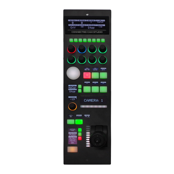
Controller Diagrams Top - RM-LP250S 1. Large display with 8 tiles. Functions associated with encoders from group 3 2. 8 user buttons 3. 8 rotary encoders with RGB backlight for function identification CONNECTED CAM STUDIO 4. Elastomer joypad 5. Group of 6 4-way buttons with associated displays 6. -
Page 6: Top - Rm-Lp250M
Top - RM-LP250M 1. Large display with 8 tiles. Functions associated with encoders from group 3 2. 8 user buttons 3. 8 rotary encoders with RGB backlight for function identification 4. Elastomer joypad CONNECTED CAM STUDIO 5. Group of 6 4-way buttons with associated displays 6. -
Page 7: Backside
1. DB9 (EXT I/O) For external routing/tally systems 2. Camera Selector Used on RM-LP250S to select camera number for Camera ID display 3. USB 2.0 Port Used for fi rmware upgrade and IP settings only 4. IP Network RJ45 Port For IP Control with PoE (48V IEEE 802.3af) -
Page 8: System Configuration
The RM-LP250M is designed to control up to 3 The controllers connects to the cameras and cameras at the same time. changes settings on the camera itself. No video signal processing are done on the RM-LP250S or the RM-LP250M. Needs to be on same subnet! Ethernet... -
Page 9: Camera Settings
USB/Ethernet Firmware adapter must be utilized from the USB2.0 HOST port. The JVC GY- HC900 must have the firmware version v0230-0217 or newer. The JVC GY HC550 must have the firmware version v0120-0166 or newer... -
Page 10: Controller Settings
When the joystick top button or the “Prev” button is pressed, a relay is shorting pin 1 and 2 For RM-LP250S: If pin 8 is shorted to GND (pin 5 or 9) the RGB Tally bar will light red and Tally... -
Page 11: Network Interface Details
Network Interface Details • The controller have a 100 mbps network interface • Network switch must have Auto-MDI/MDIX • Network switch must support 100 mbps • PoE: IEEE 802.3af Power over Ethernet (PoE) Specifications The PoE industry standard 48V IEEE 802.3af is used. -
Page 12: Controller Use
Controller Use RM-LP250S Overall the controller have two Menus. To change between the two menus press M1 and M2. The CONNECTED CAM STUDIO controller have 1 shift level. To activate this press C1 C2 C3 C4 C5 C6 C7 C8 C1-C8 Activate User Switch 1-8. - Page 13 Black ID Tally Iris Shift level via toggle M8 Connection Status Shows connection status. Button have no function Iris Displays Iris value B9-B11 Shift: Off Shift: On - Joystick Active Panel. If enabled Iris Range: Reset Points - Ring no hardware interface will - Button respond Iris one Push...
-
Page 14: Rm-Lp250M
RM-LP250M Overall the controller have two Menus. To change between the two menus press M1 and M2. To change between camera 1-3 press M4-M6. The CONNECTED CAM STUDIO controller have 1 shift level. To activate this press C1 C2 C3 C4 C5 C6 C7 C8 C1-C8 Activate User Switch 1-8. -
Page 15: Parameter Settings
Iris Shift level via toggle M8 Connection Status Shows connection status. Button have no function Iris Displays Iris value Active Panel. If enabled no hardware interface will respond Iris Wheel Iris one Push Iris Mode. Light up Red when in Auto. Green when in manual LED Bar Indicates Iris value... -
Page 16: Dimensions
Dimensions Not to scale CONNECTED CAM STUDIO 35.5 cm 10.2 cm Thickness: 0.3 cm 2.3 cm 7.2 cm 2.3 cm Not to scale 6.0 cm 24.6 cm... -
Page 17: Changing Default Configuration
Changing Default Configuration In some cases it can be desirable to change mapping of functionality on the diffrent hardware components on the controller. This is presented in the following section. If one would like to change the default username and password for authentication please see: Changing Default Username/Password for Authentication Different Mapping of Functions Coming soon... -
Page 18: Changing Default Username/Password For Authentication
Index 1: Sets Password (maximum characters = 9) Index 2: Sets port Notice for the RM-LP250S and RM-LP250M the Device Core option strings have already been set on the default configurations. This makes the procedure less error-prone. String for RM-LP250S: D0:0="jvc";D0:1="skaarhoj";D0:2=80 String for RM-LP250M: D0:0="jvc";D0:1="skaarhoj";D0:2=80;D1:0="jvc";D1:1="skaarhoj";D1:2=80;D2:0="jvc";D2:1="skaarhoj";... - Page 19 Then setting the username + password would be set by this configuration under “Manage Media” on your configuration page for your controller on cores.skaarhoj.com Example 2: Setting port could look like this device configuration code in the generic form: D0:2=12345 To confirm that a device configuration is in fact detected by the controller, please check it out on the serial monitor where it will be mentioned:...
-
Page 20: Troubleshooting
And not the number 255 iris in the LED Bar will not be shown. The iris range limitation is used to set a range for the joystick on the RM-LP250S. In order to resolve this the action “Iris Range - Reset point” must be triggered for the impacted Device... - Page 21 • Press “C1” and assign the following actions JVC RCP: Iris Range - Reset points JVC RCP #2: Iris Range - Reset points JVC RCP #3: Iris Range - Reset points Press “Save” and then press “C1” button on the RM-LP250M •...