Table of Contents
Advertisement
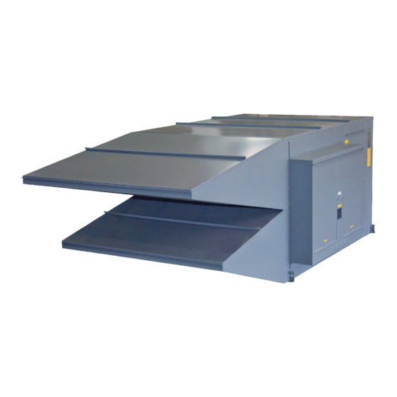
MAKE-UP AIR HEATERS
TECHNICAL MANUAL
Improper installation, adjustment, alteration, service or maintenance can cause property
damage, injury or death. Read the installation, operating, and maintenance instructions
thoroughly before installing or servicing this equipment.
The use and storage of gasoline or other flammable vapors and liquids in open containers in
the vicinity of this appliance is hazardous.
FOR YOUR SAFETY
If you smell gas:
1. Open windows.
2. Don't touch electrical switches.
3. Extinguish any open flame.
4. Immediately call your gas supplier.
Made in the USA
M-SERIES
DRAW THRU
DIRECT GAS-FIRED
WARNING:
FOR YOUR SAFETY
ASHRAE
ASHRAE
90.1
COMPLIANT
COMPLIANT
®
®
M-TM2-0120
Advertisement
Table of Contents

Related Manuals for Cambridge Air Solutions M Series


Summary of Contents for Cambridge Air Solutions M Series
- Page 1 M-SERIES DRAW THRU DIRECT GAS-FIRED MAKE-UP AIR HEATERS TECHNICAL MANUAL WARNING: Improper installation, adjustment, alteration, service or maintenance can cause property damage, injury or death. Read the installation, operating, and maintenance instructions thoroughly before installing or servicing this equipment. FOR YOUR SAFETY The use and storage of gasoline or other flammable vapors and liquids in open containers in the vicinity of this appliance is hazardous.
- Page 2 LIMITED WARRANTY Cambridge Air Solutions Limited Warranty is included within the Terms and Conditions that are sent with every Order Acknowledgement. For questions regarding Limited Warranty, contact Cambridge Air Solutions Customer Service Group at 1-800-473-4569. Cambridge Air Solutions 760 Long Road Crossing Dr.
-
Page 3: Table Of Contents
M-SERIES TECHNICAL MANUAL CONTENTS HAZARD SUMMARY ....................... 4 TYPICAL SYSTEM OVERVIEW ..................... 5 Accessory Identification ....................6 Heater/Accessory Weights ....................7 Heater Operation ........................ 8 Heater Configuration ......................8 INSTALLATION INSTRUCTIONS Uncrating Instructions ......................9 Mounting Location ......................9 Horizontal Mount – Mounting Curb ................10 Horizontal Mount –... - Page 4 Heater Roof and Wall Openings ..................75 Heater Discharge Dimensions ..................75 Gas Train Drawings ......................76 Electrical Control Enclosure Isometric Drawings ............78 M110 – M115 ......................78 M118 – M136 ......................79 M140 .......................... 80 Cambridge Air Solutions. M-Series Technical Manual...
- Page 5 Remote Control Station Components ................89 Individual Heater Component Descriptions ..............91 Damper Motor Replacement & Adjustment ..............95 Troubleshooting Guide ....................97 ANSI/ASHRAE/IESNA STANDARD 90.1 ................103 MAINTENANCE LOG ......................104 QR CODE ..........................109 M-Series Technical Manual Cambridge Air Solutions...
-
Page 6: Hazard Summary
If in doubt regarding installation or application, account, through standard engineering methods, the contact Cambridge Air Solutions Customer Service structure’s designed infiltration rate, by providing Group at 800-473-4569 during the hours of 8:00 a.m. -
Page 7: Typical System Overview
The adjustable portion of the temperature selector is typically mounted in the Remote Control Station to prevent unwanted tampering of the temperature setting and the non-adjustable space sensor is mounted in the space being heated. M-Series Technical Manual Cambridge Air Solutions... -
Page 8: Accessory Identification
Inlet Collar Inlet Elbow Mounting Curb Motorized Discharge Damper Motorized Inlet Damper Mounting Legs Single Rainhood w/ Inlet Screen Vertical Mount Vertical Mount Outdoor Configuration Indoor Configuration UNIT FSID FLASHING & TRIM BY OTHERS FLOOR Cambridge Air Solutions. M-Series Technical Manual... -
Page 9: Heater/Accessory Weights
Discharge Duct - 20" Discharge Duct - 50" Discharge Duct - 72" Discharge Damper (internal) Discharge Elbow Discharge Plenum 3-way w/enclosure Discharge Diffuser Mounting Legs 3-foot, set of 4 Mounting Legs 5-foot, set of 4 M-Series Technical Manual Cambridge Air Solutions... -
Page 10: Heater Operation
HEATER CONFIGURATION BURNER VIEWPORT MANUAL SHUT-OFF VALVE SAFETY SHUT-OFF VALVE (SSV) SHUT-OFF VALVE (SOV) ELECTRICAL / GAS CONTROL ENCLOSURE MANUAL SHUT-OFF VALVE Cambridge Air Solutions. M-Series Technical Manual... -
Page 11: Installation Instructions Uncrating Instructions
WARNING: Where the mounting height of the heater is a consideration, work platforms or service lifts should be provided for accessibility to the equipment for service and maintenance activities. M-Series Technical Manual Cambridge Air Solutions... -
Page 12: Horizontal Mount - Mounting Curb
88 3/8" 96" PITCH POCKETS OR ROOF BOOTS (BY OTHERS) RECOMMENDED. M140 Note: The V Bank Filter Section is an integral part of the M140 cabinet, thus it does not require a separate Mounting Stand/Rail. Cambridge Air Solutions. M-Series Technical Manual... - Page 13 The gas and electrical connections must not penetrate the unit base or mounting curb. Cambridge Air Solutions recommends using pitch pockets or roof boots to seal the penetrations. IMPORTANT Accurate measurements are critical and will affect installation process. M-Series Technical Manual Cambridge Air Solutions...
- Page 14 M110 - M115 Typical Curb and Discharge Duct Typical Curb and Discharge Duct Roof Opening Model M110* 17¾" 17¾" M112* 19¼" 19¼" M115* 22¼" 22¼" * DIMENSIONS ALLOW FOR ¾" CLEARANCE ON EACH SIDE Cambridge Air Solutions. M-Series Technical Manual...
- Page 15 This is an instrument of service and is the sole property WHERE USED: of Cambridge Engineering, Inc. It may not be copied, reproduced, or re-used on any other project without MDL: DWG: DATE: M-Series Technical Manual Cambridge Air Solutions agreement in writing from this company.
- Page 16 TYPICAL INSTALLATION HORIZONTAL MOUNT - ROOF TOP CONFIGURATION M140 Typical Curb and Discharge Duct Roof Opening Model M140*** 55¼" 55¼" *** DIMENSIONS ALLOW FOR 1½" CLEARANCE ON EACH SIDE Cambridge Air Solutions. M-Series Technical Manual...
-
Page 17: Horizontal Mount - Outdoor Stand Mount Configuration
INSTALLATION INSTRUCTIONS HORIZONTAL MOUNT - OUTDOOR STAND MOUNT CONFIGURATION IMPORTANT Cambridge Air Solutions recommends mounting the WARNING: heater a minimum of 24" off the mounting surface in Due to the size and weight of this equipment, it areas where snow accumulation could impact heater is recommended the heater support structure be operation. - Page 18 26½" M120*** 30½" 30½" M125*** 36" 36" M130**** 43" 43" M136**** 49" 49" *** DIMENSIONS ALLOW FOR 1½" CLEARANCE ON EACH SIDE **** DIMENSIONS ALLOW FOR 2" CLEARANCE ON EACH SIDE Typical Duct Interface Cambridge Air Solutions. M-Series Technical Manual...
- Page 19 TYPICAL INSTALLATION HORIZONTAL MOUNT - OUTDOOR STAND MOUNT CONFIGURATION M140 Wall Opening Model M140**** 56¼" 56¼" **** DIMENSIONS ALLOW FOR 2" CLEARANCE ON EACH SIDE Typical Duct Interface M-Series Technical Manual Cambridge Air Solutions...
-
Page 20: Horizontal Mount - Thru Wall Configuration
Block the heater where necessary. Use a spreader bar to prevent damage and connect slings to the lifting brackets. IMPORTANT Cambridge Air Solutions recommends mounting the heater’s rainhood a minimum of 24" off the ground or other surfaces. Cambridge Air Solutions. - Page 21 TYPICAL INSTALLATION HORIZONTAL MOUNT - THRU WALL CONFIGURATION M110 - M115 Wall Opening Model M110** 32¼" 35" M112** 32¼" 35" M115** 46¼" 35" ** DIMENSIONS ALLOW FOR 1" CLEARANCE ON EACH SIDE M-Series Technical Manual Cambridge Air Solutions...
- Page 22 55¼" M120*** 57¾" 55½" M125*** 69¾" 72¼" M130**** 92½" 73¼" M136**** 92½" 98¼" M140**** 121¾" 97¾" *** DIMENSIONS ALLOW FOR 1½" CLEARANCE ON EACH SIDE **** DIMENSIONS ALLOW FOR 2" CLEARANCE ON EACH SIDE Cambridge Air Solutions. M-Series Technical Manual...
-
Page 23: Vertical Mount - Outdoor Configuration
IMPORTANT engineer before installing this equipment. Cambridge Air Solutions recommends mounting the heater a minimum of 60" off the mounting surface in areas where snow accumulation could impact the heater IMPORTANT operation. - Page 24 Install hanging rods 3/8" the setup instructions provided with this manual. minimum from ceiling supports to the plenum’s support brackets. 12. For M136 Inlet Elbow and Rain Hoods assembly, see field assembly instructions provided with components. Cambridge Air Solutions. M-Series Technical Manual...
- Page 25 Model M118*** 26½" 26½" M120*** 30½" 30½" M125*** 36" 36" M130**** 43" 43" M136**** 49" 49" *** DIMENSIONS ALLOW FOR 1½" CLEARANCE ON EACH SIDE **** DIMENSIONS ALLOW FOR 2" CLEARANCE ON EACH SIDE M-Series Technical Manual Cambridge Air Solutions...
- Page 26 Model M118*** 26½" 26½" M120*** 30½" 30½" M125*** 36" 36" M130**** 43" 43" M136**** 49" 49" *** DIMENSIONS ALLOW FOR 1½" CLEARANCE ON EACH SIDE **** DIMENSIONS ALLOW FOR 2" CLEARANCE ON EACH SIDE Cambridge Air Solutions. M-Series Technical Manual...
-
Page 27: Vertical Mount - Indoor Configuration
VERTICAL MOUNT - INDOOR CONFIGURATION IMPORTANT WARNING: Cambridge Air Solutions recommends mounting the Due to the size and weight of this equipment, it is heater’s rain hood a minimum of 60" off the ground or recommended the heater support be reviewed and... - Page 28 14. Adjust internal vibration isolation, if applicable, per the setup instructions provided with this manual. 11. Install the discharge accessory by screwing the accessory to the heater. Install hanging rods from the ceiling supports to the accessory̓s support brackets. Cambridge Air Solutions. M-Series Technical Manual...
- Page 29 Model M118*** 51¾" 56" M120*** 57¾" 56" M125*** 69¾" 72½" M130**** 92½" 73½" M136**** 104" 83½" *** DIMENSIONS ALLOW FOR 1½" CLEARANCE ON EACH SIDE **** DIMENSIONS ALLOW FOR 2" CLEARANCE ON EACH SIDE M-Series Technical Manual Cambridge Air Solutions...
-
Page 30: Gas Piping
Failure to comply will void the or mounting curb. Cambridge Air Solutions warranty. recommends using pitch pockets or roof boots to If the test pressure is less than or equal to 1/2 PSIG seal the penetrations. -
Page 31: Electrical
WARNING: temperature control options using Class 2 wiring For roof mounting, the gas and electrical per Cambridge Air Solutions wiring diagram and connections must not penetrate the unit base National Electrical Code Article 725 or local codes. or mounting curb. Cambridge Air Solutions 6. -
Page 32: Start-Up Instructions
Verify the field wiring, both primary and (page 32) control, has been installed according to the 8. Gas Valve Leak Check Cambridge Air Solutions wiring diagram and (page 33) the National Electrical Code. 9. Gas Train Leak Check Verify that a sediment trap has been provided (page 34) upstream of other gas train components. - Page 33 Turn the blower service switch to the “LOCAL” regulator is needed and has not been installed, position. (Note: The burner service switch must check with your local Cambridge Air Solutions remain in the “OFF” position) representative or Cambridge Air Solutions’...
- Page 34 FLA. High amperage may indicate excessive blower increase or decrease the pressure drops, as RPM. Call the Cambridge Air Solutions Customer required. Hold the adjusting nut and retighten Service Group at 800-473-4569 if unable to obtain the jam nut to secure the mechanism.
- Page 35 "LOCAL" position. properly zeroed. Turn the burner service switch to the b.1. On single redundant valve applications “ ” LOCAL position. After a delay for pre- (heaters rated less than 400,000 Btu/ M-Series Technical Manual Cambridge Air Solutions...
- Page 36 " (approximately 1-1/2" to 2 long that is WARNING: evenly spread across the burner (without Do not use flame to leak check piping. gaps). Cambridge Air Solutions. M-Series Technical Manual...
- Page 37 PC board as shown in page 34). the drawing. Only minor adjustments are normally required to obtain the proper v. Remove the meter and reattach the red wire to terminal FP on the FSR board. setting. M-Series Technical Manual Cambridge Air Solutions...
- Page 38 Air Solutions Customer Service Group at 800-473-4569 this application. Refer to Individual during the hours of 8:00 a.m. to 5:00 p.m. Central Time, Component Description Section for Monday through Friday. additional information (page 89). Cambridge Air Solutions. M-Series Technical Manual...
-
Page 39: Vfd Start-Up Instructions
10’ from any intake opening. Vent check with your local Cambridge Air Solutions piping cannot be reduced and cannot representative or Cambridge Air Solutions’s exceed 20’... - Page 40 If the pressure measured on the photohelic gauge does “OFF” position. not settle between the two orange needles, please contact Cambridge Air Solutions’s Customer Service Group at a. Place the blower service switch in the 800-473-4569. “LOCAL” position and verify the VFD display is still in the “HAND”...
- Page 41 A) in order to verify the minimum FLA. High amperage may indicate excessive blower fire flame signal during the adjustment RPM. Call the Cambridge Air Solutions Customer process. Connect the meter by removing Service Group at 800-473-4569 if unable to obtain the red wire from terminal FP of the flame acceptable Amperage readings.
- Page 42 To correct this condition, either adjust the manifold pressure regulator to reduce the manifold pressure or increase the blower speed, provided the motor full load amps are not exceeded. Cambridge Air Solutions. M-Series Technical Manual...
- Page 43 Pressure above. If the manifold pressure and document. reading does not equal this value, adjust the low speed kit (LSK) until the proper manifold pressure is obtained. The LSK is a resistor that limits the voltage from M-Series Technical Manual Cambridge Air Solutions...
- Page 44 If the reading is greater than 0 inch WC, replace the gas valve and retest. If the reading is 0 inch WC, remove the manometer and reinstall the pipe plug. b.2. On heaters with separate redundant valves, Cambridge Air Solutions. M-Series Technical Manual...
- Page 45 For the Maxitrol Series 44 control system, set the “MIN” and “MAX” setting of the amplifier to the application specifications. e. Verify the blower and burner service switches are in the “REMOTE” position. M-Series Technical Manual Cambridge Air Solutions...
-
Page 46: Operating Instructions Operating Sequence
10. Igniter is de-energized. 11. Low Fire Start is de-energized after 15 seconds. 12. Unit runs and modulates until operating thermostat and/or interlock opens (heater shuts off). 13. Steps (2) through (12) repeat themselves automatically as necessary. Cambridge Air Solutions. M-Series Technical Manual... -
Page 47: Electronic Thermostat
OPERATING INSTRUCTIONS ELECTRONIC THERMOSTAT The Cambridge Air Solutions Operating Electronic Thermostat (OET) controls the heater’s ON/OFF operation in a space heating mode. It includes the following features: • Digital LED display of current temperature and temperature settings. • LED indication of status of output relay. - Page 48 (-) the measured temperature. 2. Press and hold the button while pressing HEAT OFF or the button until the desired DOWN temperature for the heater to turn OFF is displayed. Cambridge Air Solutions. M-Series Technical Manual...
-
Page 49: Tss Controller
OPERATING INSTRUCTIONS TSS CONTROLLER The Cambridge Air Solutions TSS Controller provides several features to tailor the operation of the Cambridge heating system to particular applications. • Seven day programmable clock • Separate temperature settings for Heating and Setback operation • Separate schedules for Summer Ventilation and Heating modes •... - Page 50 SETTING AUTOMATIC ADJUSTMENT FOR DAYLIGHT SAVING TIME The TSS Controller has the ability to automatically detect and adjust for daylight saving time. The default setting on the controller is to recognize daylight saving time. Cambridge Air Solutions. M-Series Technical Manual...
- Page 51 "YES" if daylight DOWN saving time should be recognized or "NO" if daylight saving time is not recognized. 4. Press the button to exit SETBACK SCHEDULE/EXIT the scheduling program. M-Series Technical Manual Cambridge Air Solutions...
- Page 52 TSS panel, will override the SETBACK temperature setting and increase the space temperature to the HEAT ON and HEAT OFF temperature settings for the amount of time set on the OVERRIDE timer. Cambridge Air Solutions. M-Series Technical Manual...
- Page 53 Off 10 On 11 On 11 Off 11 Off 11 On 12 On 12 Off 12 Off 12 On 13 On 13 Off 13 Off 13 On 14 On 14 Off 14 Off 14 M-Series Technical Manual Cambridge Air Solutions...
- Page 54 ON time. DOWN 9. Press and bold the button while DAY OF WEEK pressing the or the button until the light DOWN for the desired day is illuminated. Cambridge Air Solutions. M-Series Technical Manual...
- Page 55 HED 7 SETBACK SCHEDULE/EXIT the scheduling program. HSD 8 HED 8 15. Verify that the correct current time and light for day HSD 9 of the week are still displayed. HED 9 M-Series Technical Manual Cambridge Air Solutions...
- Page 56 DOWN desired holiday start date. 6. Repeat steps 2-5 until all required holiday cycles have been entered. 7. Press the button to exit SETBACK SCHEDULE/EXIT the scheduling program. Cambridge Air Solutions. M-Series Technical Manual...
- Page 57 (A period [.] after the F will indicate the Calibration Mode). 2. Pressing the or the button will display the DOWN current calibration difference above or below (-) the measured temperature. M-Series Technical Manual Cambridge Air Solutions...
-
Page 58: Bacnet Controller
• Selectable operating modes (unit heater / makeup air / summer ventilation) • Removable screw terminal blocks • Onboard USB port for firmware upgrades • Local user interface display for commissioning and monitoring POWER FAULT SA BUS FC BUS MODBUS Cambridge Air Solutions. M-Series Technical Manual... - Page 59 EOL to third-party devices with only + and - terminals. Terminator Supply Power Terminals To 24 VAC Class 2 Power Supply FC or Bus Cable from Previous Device on Daisy-Chained Bus Segment FC or N2 Bus Terminals M-Series Technical Manual Cambridge Air Solutions...
- Page 60 Discharge Set Point based on PID loop. 3. If Zone Temperature is above Zone Set Point plus Differential then Supply Fan and Burner stop. 4. Burner will not operate if Outdoor Temperature is above Heating Lockout Set Point. Cambridge Air Solutions. M-Series Technical Manual...
- Page 61 Blink - 2 Hz = Data Transmission (normal communication) Mod Bus Green Blink - 2 Hz Off Steady = No Data Transmission (Auto baud in progress) On Steady = Communication lost, waiting to join. M-Series Technical Manual Cambridge Air Solutions...
-
Page 62: Maintenance Instructions
M136/ or moist location, high 9/16" 8 - 10 7 - 9½ M140 vibration) M140 50-60 9/16" 4 or M140 50-60 9/16" 9-11 8-10 M140 9/16" 10-12 9-11 8½ - M140 9/16" 8-10 10½ Cambridge Air Solutions. M-Series Technical Manual... -
Page 63: Blower Cleaning
Refer to step 8, Gas Valve Leak Check, of the Start-up Procedures (see page 33). BURNER CLEANING The Cambridge Air Solutions burner is for the most part WARNING: self-cleaning. However, if the application is extremely dirty or dusty, it may become necessary to periodically In the extreme case, faulty valve operation will clean the burner. -
Page 64: Asco Gas Valves
7. Replace the valve bonnet and the bonnet screws (6). Torque the screws in a crisscross manner to 100 ± 10 in-lbs. Replace the solenoid and make the electrical hookup. Cambridge Air Solutions. M-Series Technical Manual... - Page 65 ASCO Rebuild Kit. ∗ BONNET SCREW ∗ BLEED HOLE Locate bleed hole in ∗ core/diaphragm sub--- assembly approximately 30° from valve inlet CAUTION Do not damage valve seat Disassembled View of ASCO Valve M-Series Technical Manual Cambridge Air Solutions...
-
Page 66: Filters
If soap is used, ensure that all soap is rinsed out of the filter. Visually inspect the filter to ensure that it is clean. Allow to dry before returning to service. Cambridge Air Solutions. M-Series Technical Manual... - Page 67 * Continuous filters are manufactured in lengths of 24 panels. Cut filter panels like chain links. For example, 6 (2x3) means cut 2 rows x 3 panels long for total of 6 panels of this type. Cut only between filter panels. M-Series Technical Manual Cambridge Air Solutions...
-
Page 68: Direct Evaporative Cooling (Dec)
NOTE: Indicates a situation that could result in • Failure to follow recommendations could result in equipment or property damage, or provides important death or serious injury. information on installation considerations. Cambridge Air Solutions. M-Series Technical Manual... -
Page 69: Receiving
2. Measure DEC for correct sizes. Immediately contact safety margin. Cambridge Air Solutions if unit’s openings do not match. 3. Check for proper air flow direction. NOTE: Ensure all local building and electrical codes are fully complied with in installing the unit. -
Page 70: Plumbing/Fill And Drain Valves
Auto Drain with Freeze Protection (Optional) Install two-way drain valve (supplied by Cambridge Air Solutions, as an option, and installed by Contractor) on the sump’s drain connection. Install three-way fill valve (supplied by Cambridge Air Solutions, as an option, and installed by Contractor) under the roof-line with port “AB”... -
Page 71: Fill And Drain Valve Schematic
NOTE: ALL PLUMBING, PIPING, AND FIXTURES EXTERNAL TO UNIT ARE TO BE NOTE: ALL PLUMBING, PIPING, AND FIXTURES EXTERNAL TO UNIT ARE TO BE FURNISHED AND FURNISHED AND INSTALLED BY OTHERS UNLESS OTHERWISE INDICATED. INSTALLED BY OTHERS UNLESS OTHERWISE INDICATED. M-Series Technical Manual Cambridge Air Solutions... -
Page 72: Drain, Overflow And Make-Up Water Piping For Autodrain With Freeze Protection
FROM UNIT 2 WAY VALVE* 3 WAY VALVE* FILL & DRAIN KIT (FIELD INSTALLED & WIRED) NOTE: *Wiring may change if pumps provided by others. **All wiring must comply with local and national electrical codes. Cambridge Air Solutions. M-Series Technical Manual... -
Page 73: Electrical Panel/Wiring
NOTE: Power supplied and installed by others. • All installations should be performed in accordance to local and state codes and with proper permits. • Wire unit according to approved submittals and wiring diagram. M-Series Technical Manual Cambridge Air Solutions... -
Page 74: Media Cooling Pads Operating Installation
MEDIA COOLING PADS OPERATING INSTALLATION: MEDIA COOLING PADS OPERATING INST ALLATION NOTE: SEE ADDITIONAL INFORMATION ON CARE OF MUNTERS MEDIA IN SUPPLEMENTAL INFORMATION. NOTE: See additional information on care of Munters media in Supplemental Information. Cambridge Air Solutions. M-Series Technical Manual... -
Page 75: Initial Start-Up
(Initial factory set position of valve is ½ open). WARNING: 15. After running Cambridge Air Solutions DEC for Whenever power is interrupted, the 24-hour clock (1) week adjust factory pre-set bleed valve(s). must be reset to local time. -
Page 76: Normal Operations
2. Check media pads for scaling and adjust bleed valve as required. 3. Inspect for water carryover and leaks. 4. Inspect air flow making sure no outside air is bypassing media pads. Cambridge Air Solutions. M-Series Technical Manual... -
Page 77: Reference
20¾" M118* 21 7/8" 18¾" 23½" 23½" M120* 24½" 24¾" 27½" 27½" M125* 31¼" 31¼" 33" 33" M130* 36 5/8" 36 5/8" 39" 39" M136* 42½" 42¾" 45" 45" M140 50" 50" 52¼" 52¼" M-Series Technical Manual Cambridge Air Solutions... -
Page 78: Gas Train Drawings
> 400 MBH Low Pressure ELECTRIC SHUT-OFF VALVE (SOV) CSA Certified ELECTRIC SAFETY SHUT-OFF VALVE (SSV) Horizontal Mount > 400 MBH High Pressure CSA Certified ELECTRIC SAFETY SHUT-OFF VALVE (SSV) ELECTRIC SHUT-OFF VALVE (SOV) Cambridge Air Solutions. M-Series Technical Manual... - Page 79 CSA Certified ELECTRIC SHUT-OFF VALVE (SOV) ELECTRIC SAFETY SHUT-OFF VALVE (SSV) Horizontal Mount > 400 MBH XL GAPS Compliant formerly Industrial Risk Insurers (IRI) CSA Certified ELECTRIC SAFETY SHUT-OFF VALVE (SSV) ELECTRIC SHUT-OFF VALVE (SOV) M-Series Technical Manual Cambridge Air Solutions...
-
Page 80: Electrical Control Enclosure Isometric Drawings
REFERENCE ELECTRICAL CONTROL ENCLOSURE ISOMETRIC DRAWING M110 - M115 Cambridge Air Solutions. M-Series Technical Manual... -
Page 81: M118 - M136
REFERENCE ELECTRICAL CONTROL ENCLOSURE ISOMETRIC DRAWING M118 - M136 M-Series Technical Manual Cambridge Air Solutions... -
Page 82: M140
ELECTRICAL CONTROL ENCLOSURE ISOMETRIC DRAWING M140 Cambridge Air Solutions. M-Series Technical Manual... -
Page 83: Electrical Wiring Diagrams
Entering Air Thermostat Low Temperature Cutout Switch - SOV Leak Test Exhaust Fan Interlock Motor Multi-Tap Transformer (24&120 Volt) Motor Starter Class 2 Transformer (24 Volt) Flame Rod Flame Safeguard Relay Modulating Valve Temperature Sensor M-Series Technical Manual Cambridge Air Solutions... -
Page 84: Series 14 Kitchen Ventilation System
Entering Air Thermostat Motor - Supply Fan Class 2 Transformer (24 Volt) Fire Protection Interlock Motor Starter - Supply Fan Temperature Sensor Flame Rod Motor Starter - Exhaust Fan Flame Safeguard Relay Modulating Valve Cambridge Air Solutions. M-Series Technical Manual... -
Page 85: Series 44 M140
Switch - SOV Leak Test Entering Air Thermostat Motor Multi-Tap Transformer (24&120 Volt) Flame Rod Motor Starter Class 2 Transformer (24 Volt) Flame Safeguard Relay Modulating Valve Temperature Sensor Fuse 24 Volt Control Overload Relay M-Series Technical Manual Cambridge Air Solutions... -
Page 86: Series 44 Tamperproof Controls /Operating Thermostat
Class 2 Transformer (24 Volt) Exhaust Fan Interlock Overload Relay Tamper Proof Space Sensor Flame Rod Temperature Sensor Flame Safeguard Relay Purge Timer R1A&R1B Relay Gas Valve Fuse 24 Volt Control Relay - Intermittent/Continuous Fuse 120 Volt Control Cambridge Air Solutions. M-Series Technical Manual... -
Page 87: Series 44 Temperature Setback System/Temperature Averaging
Flame Safeguard Relay Overload Relay Class 2 Transformer (24 Volt) Fuse 24 Volt Control Purge Timer Tamper Proof Space Sensor Fuse 120 Volt Control R1A&R1B Relay - Gas Valve Temperature Sensor Temperature Setback System M-Series Technical Manual Cambridge Air Solutions... -
Page 88: Series 44 Tamperproof Controls/ Variable Frequency Drive/ Room Pressure
Modulating Valve Tamper Proof Space Sensor Flame Safeguard Relay Profile Damper Adjustment Temperature Sensor Fuse 24 Volt Control Profile Damper Motor Variable Frequency Drive Fuse 120 Volt Control Purge Timer High Gas Pressure Switch Cambridge Air Solutions. M-Series Technical Manual... -
Page 89: Connection Diagram
FOR MAXITROL SERIES 44 SYSTEMS AND SERIES 14 SYSTEMS WITH RHA CONTROL USE 2 WIRE SHIELDED TWISTED-PAIR 18 AWG MINIMUM RUN SEPARATE FROM ALL OTHER AC WIRING GROUND SHIELD AT REMOTE CONTROL STATION ONLY M-Series Technical Manual Cambridge Air Solutions... -
Page 90: Gas Control Systems
Maxitrol 44 above) or operated intermittently based on a thermostat at maximum discharge temperature for space heating. Requires Maxitrol 44 controls and a signal to switch between modes (Exhaust Fan Interlock, Temperature Setback System, Manual Make-Up Air Switch, etc.) Cambridge Air Solutions. M-Series Technical Manual... -
Page 91: Remote Control Station Components
Includes an adjustable pressure switch switch contact to automatically increase the discharge mounted in the make-up air heater control enclosure to temperature. monitor the pressure drop across the filters. M-Series Technical Manual Cambridge Air Solutions... - Page 92 4. Separate and strip the ends of the lead wires 3/8". 5. Open the terminal blocks for the sensor connections. Figure 2 6. Insert the lead wires and close the terminal blocks to the locked position. Cambridge Air Solutions. M-Series Technical Manual...
-
Page 93: Individual Heater Component Descriptions
The disconnect must be off before accessing the electrical control enclosure. Once the control enclosure is open, experienced service technicians may activate the electrical circuit to assist in troubleshooting. M-Series Technical Manual Cambridge Air Solutions... - Page 94 The high gas pressure switch should be set at 25% above manifold gas pressure. The adjustment screw is located under the top plate. Cambridge Air Solutions. M-Series Technical Manual...
- Page 95 MR212 valve, the minimum fire adjusting screw is located under the large dust cover. The MR212 modulating valve also serves as the manifold pressure regulator to control the burner manifold pressure. The MR212 is rated for 5 PSIG. M-Series Technical Manual Cambridge Air Solutions...
- Page 96 In the “LOCAL” or “OFF” position, the service technician has local control of the heater. These switches must be placed in the “REMOTE” position for normal control from the Remote Control Station. Cambridge Air Solutions. M-Series Technical Manual...
-
Page 97: Damper Motor Replacement & Adjustment
3/8" diameter clevis pin. Do not switch plunger being the twelve o’clock reference connect the damper linkage at this time. position. If it is beyond the four o’clock position, use M-Series Technical Manual Cambridge Air Solutions... - Page 98 Do not over-drive the damper motor as damage to the PC board or tripping of the onboard fuse may result. If the fuse trips, place the blower service switch in the “OFF” position for 15 seconds to allow fuse to reset. Cambridge Air Solutions. M-Series Technical Manual...
-
Page 99: Troubleshooting Guide
13. Blower Damage a) Defective or locked bearings a) Replace bearings. b) Physical damage b) Replace or repair blower. 14. Belts a) Belt Slipping a) Tighten belts. b) Belt broken or missing b) Replace belts. M-Series Technical Manual Cambridge Air Solutions... - Page 100 6. Multi-Functional PC Board a) Low fire start set too low a) Adjust modulating valve voltage between 10 and 13 Volts DC. b) Thermistor open or not connected b) Properly install or replace thermistor. Cambridge Air Solutions. M-Series Technical Manual...
- Page 101 Defective FSR a) Replace FSR. 3. Operating Thermostat a) Differential temperature setting too tight a) Increase differential temperature setting. 4. Damper Motor End Switch a) End switch making intermittent contact a) Replace end switch assembly. M-Series Technical Manual Cambridge Air Solutions...
- Page 102 Replace the sensor if the resistance measured is more than: 7,000 Ω for the T244; 5,500 Ω for the TS244; or 2,250 Ω for the TD244. b) Induced voltage in field wiring b) Utilize shielded, twisted pair wiring. c) Space sensor located improperly c) Sensor in cold draft - relocate Cambridge Air Solutions. M-Series Technical Manual...
- Page 103 Short in sensor circuit a) Replace the sensor if the resistance measured at: terminals 1 and 2 on TS114 is less than 8,000 Ω; terminals 1 and 3 or 2 and 3 on TS144 is less than 2,900 Ω. b) Temperature control system out of b) Perform temperature control system calibration calibration. M-Series Technical Manual Cambridge Air Solutions...
- Page 104 3. Space Temperature Selector (T244A or TS244A/TD244A) a) Induced voltage in field wiring a) Utilize shielded, twisted pair wiring. 4. Remote Heat Adjust (TD114) a) Induced voltage in field wiring a) Utilize shielded, twisted pair wiring. Cambridge Air Solutions. M-Series Technical Manual...
-
Page 105: Ansi/Ashrae/Iesna Standard 90.1
Standard 90.1: • Controls (Section 6.4.3) Total airflow of all heaters less than 10,000 cfm - The Cambridge Air Solutions Temperature Setback System (TSS) will meet the standard. A properly configured building DDC system with the necessary programming for zone control, automatic shutdown and setback can also meet the standard. -
Page 106: Maintenance Log
MAINTENANCE LOG M O D E L N O . S E R I A L N O . Date Activity Technician Cambridge Air Solutions. M-Series Technical Manual... - Page 107 MAINTENANCE LOG M O D E L N O . S E R I A L N O . Date Activity Technician M-Series Technical Manual Cambridge Air Solutions...
- Page 108 Cambridge Air Solutions. M-Series Technical Manual...
- Page 109 M-Series Technical Manual Cambridge Air Solutions...
- Page 110 Cambridge Air Solutions. M-Series Technical Manual...
-
Page 111: Qr Code
SCAN THIS CODE TO ACCESS OUR ”HOW-TO” SERVICE VIDEOS ONLINE. https://www.cambridgeair.com/parts-service/how-to-service-videos Cambridge Air Solutions reserves the right to change specifications, modify the design and/or substitute equivalent materials without notice as the result of code requirements, product enhancements, ongoing research/development and vendor changes beyond our control. - Page 112 760 Long Road Crossing Dr., Chesterfield, MO 63005 Phone: (636) 532-2233 (800) 899-1989, Fax: (636) 530-6133 www.cambridgeair.com...
Need help?
Do you have a question about the M Series and is the answer not in the manual?
Questions and answers