Table of Contents
Advertisement
Available languages
Available languages
Quick Links
Original Assembly Guide
Read these instructions carefully
Guide d'assemblage d'origine
Lisez attentivement ces instructions
Original-Montageanleitung
Diese Anweisungen sorgfältig lesen.
Guida al montaggio originale
Leggere attentamente queste istruzioni
Montagehandleiding
Gelieve deze handleiding zorgvuldig te lezen
Original written in UK English
Date Published: 16 / 11 / 2016
Advertisement
Table of Contents

Related Manuals for Evolution RAGE3+


Summary of Contents for Evolution RAGE3+
- Page 1 Original Assembly Guide Read these instructions carefully Guide d’assemblage d’origine Lisez attentivement ces instructions Original-Montageanleitung Diese Anweisungen sorgfältig lesen. Guida al montaggio originale Leggere attentamente queste istruzioni Montagehandleiding Gelieve deze handleiding zorgvuldig te lezen Original written in UK English Date Published: 16 / 11 / 2016...
-
Page 2: Table Of Contents
www.evolutionpowertools.com TABLE OF CONTENTS Overview of Mitre Saw Tools Needed Watch and Learn Assembly Guide Know the Parts Assembly Procedure Inserting the carriage slide Attaching the cutting head Routing the power cable Unlatching & Raising the Cutting Head Fitting the blade Rear support arm Assembly Safety Checks Final Safety Checks Carefully remove all of the parts from the packaging and check that all parts are present... -
Page 3: Overview Of Mitre Saw
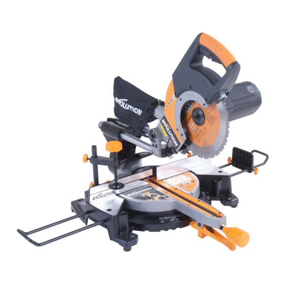
www.evolutionpowertools.com OVERVIEW OF MITRE SAW 1. Dust Bag * 11. Work piece Support * 21. Repeat End Stop * 2. On/Off Trigger Switch 12. Mounting Hole (X4) 22. Base 3. Blade Guard Release Trigger 13. Arbor Lock Button 23. Table Top (EU Models)/Lock-Off Button 14. -
Page 4: Tools Needed
www.evolutionpowertools.com TOOLS NEEDED FOR ASSEMBLY & ADJUSTMENTS SUPPLIED NOT SUPPLIED 6mm Hex Key Flat Bladed (Blade Change) Screwdriver (See Fig. 9 Page 11) - Page 5 ASSEMBLY VIDEO ON YOUR SMART PHONE Make sure the HD setting is on. QR CODE DOWNLOAD A FREE QR READER APP AND SCAN THE QR CODE (ABOVE). ® You can also view the Assembly Video online located in the ‘Evolution Support Videos’ section at: www.evolutionpowertools.com/videos/setups/...
-
Page 6: Assembly Guide
www.evolutionpowertools.com ASSEMBLY GUIDE Mitre Saws Assembly Instructions. Your Mitre Saw is supplied as 3 major component parts which need assembling. THE ASSEMBLY PROCESS IS A ‘ONE TIME ASSEMBLY’ . Once assembly is successfully completed no attempt to disassemble the machine should be made. The blade and some other smaller parts also need to be fitted by the operator. -
Page 7: Know The Parts
www.evolutionpowertools.com KNOW THE PARTS The 3 main component parts to be assembled are: • The Base and Bevel Neck. (Fig. 1a) • The Carriage Slides. (Fig. 1b) • The Cutting Head in the locked down position. (Fig. 1c) Fig. 1a WHITE Fig. 1b Fig. 1c... - Page 8 www.evolutionpowertools.com Also to be fitted are: SPACER • The Mitre Locking Handle. (Fig. 2a) • The Positive Stop Locking Lever. (Fig. 2b) • The Slide Locking Screw and anti-vibration spring (Fig. 2c) • The Blade. (Fig. 2d) Note: One of two types of Mitre Locking Handle will be SHORT MITRE supplied, according to the machine purchased. Only the LOCKING HANDLE short mitre locking handle requires the spacer.
-
Page 9: Assembly Procedure
www.evolutionpowertools.com ASSEMBLY PROCEDURE Select the Carriage Slide and Rotary Base and Bevel Neck. Fitting the Mitre Locking Handle The threaded rod of the Mitre Locking Handle slides into a MITRE tunnel, or screws into a boss (according to type of machine LOCKING HANDLE purchased) located just above the Positive Stop Locking Lever. -
Page 10: Inserting The Carriage Slide
www.evolutionpowertools.com INSERTING THE CARRIAGE SLIDE The Carriage Slides two arms should be inserted into the two linear bearings in the Bevel Neck. From the BACK of the machine the red lug should be to the left and the white lug should be to the right. - Page 11 www.evolutionpowertools.com • Lock the Sliding Carriage Arms into position using the Sliding Carriage Locking Screw. (Fig. 7) Sliding Carriage Locking Screw Lock Fig. 7 Note: If for any reason (transit damage, unpacking error, operator mistake etc.) the locating lugs have been tripped (Fig. 8) the Sliding Carriage cannot be fitted into the Bevel Neck or onto the Cutting Head until they are reset. To reset the locating lugs: • Gently push down on the tripped locating lug.
-
Page 12: Attaching The Cutting Head
www.evolutionpowertools.com ATTACHING THE CUTTING HEAD Cutting Head Carriage WARNING: The power cable must not be allowed to fall Slide through or between the two arms of the Slide Carriage. Arms The cable could be damaged if it becomes trapped by any of the machines moving parts. -
Page 13: Routing The Power Cable
www.evolutionpowertools.com ROUTING THE POWER CABLE WARNING: The power cable must not be allowed to fall through or between the two arms of the Slide Carriage. The cable could be damaged if it becomes trapped by any of the machines moving parts. Ensure that the Cutting Head is in the locked down position with the Cutting Head Latching Pin fully engaged in its socket. -
Page 14: Unlatching & Raising The Cutting Head
Fig. 16 WARNING: Only use genuine Evolution blades or those blades specifically recommended by Evolution Power Tools and which are designed for this machine. Ensure that the maximum speed of the blade is higher than the speed of the machine’s motor. -
Page 15: Rear Support Arm
www.evolutionpowertools.com • Ensure that the blade and blade flanges are clean and free from any contamination. • The inner-blade flange should be left in place (except for North American models supplied with the silver dual-sided inner- flange), but if it is removed for cleaning it must be replaced the same way round as it was removed from the machine. To insert the blade Press the Lower Blade Guard Release Trigger (A) rotate the lower blade guard (B) up into the upper blade guard and hold the lower blade guard in that position. -
Page 16: Assembly Safety Checks
www.evolutionpowertools.com ASSEMBLY SAFETY CHECKS Part Condition Slides Inserted through the bevel neck and connected to the cutting head. Locating lugs successfully deployed. Slide Carriage Inserted into threaded hole in the Bevel Neck. Locking Screw Anti-vibration spring fitted beneath the Locking Screw Hand Knob. Positive stop Installed onto locking mechanism. locking lever Mitre locking Installed onto locking screw. handle Power cable Routed correctly and fastened to back slide bracket. -
Page 17: Final Safety Checks
www.evolutionpowertools.com FINAL SAFETY CHECKS Part Condition Blade Blade installed with the rotation arrows on the blade matching the rotation arrows on the upper blade guard. Outer blade flange and arbor screw and washer correctly fitted. Safety guards Retractable lower blade guard fully operational. Cutting Head Locks in upper position with blade covered. - Page 18 ®...
- Page 19 FRANÇAIS Traduction des instructions d’origine...
- Page 20 www.evolutionpowertools.com SOMMAIRE Aperçu de la scie à onglet Outils à prévoir Démo filmée Guide d'assemblage Connaissance des pièces Procédure d'assemblage Insertion des glissières du chariot de guidage Fixation de la tête de coupe Acheminement du câble électrique Déverrouillage et levage de la tête de coupe Installation de la lame Bras de soutien arrière Contrôles de sécurité...
- Page 21 www.evolutionpowertools.com APERÇU DE LA SCIE À ONGLET 1. Sac de récupération des 9. Serre-flan 20. Carter de lame inférieur poussières * 10. Guide rétractable 11. Support de pièce à 21. Butée de reprise * 2. Déclencheur marche/arrêt 3. Déclencheur de blocage découper * 22.
- Page 22 www.evolutionpowertools.com OUTILS À PRÉVOIR POUR L’ASSEMBLAGE ET LES RÉGLAGES DE LA SCIE FOURNI NON FOURNI 6mm Clé hexagonale Tournevis (pour changer la lame) plat (voir Fig. 9 Page 29)
- Page 23 TÉLÉCHARGEZ UNE APPLI LECTEUR DE CODE QR GRATUITE ET SCANNEZ LE CODE QR (CI-DESSUS). ® Vous pouvez aussi regardez la vidéo de l’assemblage en ligne, à la rubrique « Evolution Support Videos » (Vidéos de support technique Evolution) à l’adresse : www.evolutionpowertools.com/videos/setups/...
- Page 24 www.evolutionpowertools.com GUIDE D’ASSEMBLAGE Instructions d’assemblage des scies à onglet. Votre scie à onglet se compose de trois pièces principales à assembler. LE PROCÉDÉ D’ASSEMBLAGE EST UN ‘UN ENSEMBLE DE TEMPS’ . Une fois la machine correctement assemblée, elle ne doit plus être démontée. L’opérateur de la scie devra aussi installer la lame et d’autres petites pièces.
- Page 25 www.evolutionpowertools.com CONNAISSANCE DES PIÈCES Les trois pièces principales à assembler sont : Le socle et le col de biseau (Fig. 1a). • Les glissières du chariot de guidage (Fig. 1b). • La tête de coupe bloquée à la fermeture. (Fig. 1c). • Fig. 1a ROUGE BLANC Fig. 1b Fig. 1c...
- Page 26 www.evolutionpowertools.com Les pièces suivantes sont à installer également : ENTRETOISE • Poignée de blocage de l’onglet (Fig. 2a). • Levier de blocage de butée fixe (Fig. 2b). • Vis de blocage des glissières et ressort antivibratoire (Fig. 2c) • Lame (Fig. 2d). POIGNÉE Remarque : selon la machine achetée, l’équipement est livré COURTE DE BLOCAGE avec un des deux types de poignée de blocage de l’onglet. DE L’ONGLET Seule la poignée courte de blocage de l’onglet oblige à...
- Page 27 www.evolutionpowertools.com PROCÉDURE D’ASSEMBLAGE Sélectionnez les glissières du chariot de guidage et le socle rotatif, ainsi que le col de biseau. Installation de la poignée de blocage de l’onglet POIGNÉE DE La tige filetée de la poignée de blocage de l’onglet s’insère BLOCAGE DE dans un «...
- Page 28 www.evolutionpowertools.com INSERTION DES GLISSIÈRES DU CHARIOT DE GUIDAGE Insérez les deux bras des glissières du chariot de guidage dans les deux paliers linéaires du col de biseau. Regardez l’ARRIÈRE de la machine et placez les ergots rouge et blanc respectivement à gauche et à droite. (Fig. 5) Rouge Blanc VUE DE L’ARRIÈRE Fig.
- Page 29 www.evolutionpowertools.com • Bloquez les bras du chariot de guidage à l’aide de la vis de blocage du chariot de guidage. (Fig. 7). Vis de blocage chariot Bloquer Fig. 7 Remarque : Si pour une raison quelconque (dégât de transport, erreur de déballage, erreur de l’opérateur, etc.) les ergots de centrage ont été déclenchés (Fig. 8), vous ne pourrez pas monter le chariot de guidage sur le col de biseau ou sur la tête de coupe avant de les avoir réinitialisés.
- Page 30 www.evolutionpowertools.com FIXATION DE LA TÊTE DE COUPE Cutting Head Carriage AVERTISSEMENT : le câble électrique ne doit pas tomber à Slide travers ou entre les deux bras du chariot de guidage. Arms Les pièces mobiles de la machine risquent de coincer le câble et de l’endommager.
- Page 31 www.evolutionpowertools.com ACHEMINEMENT DU CÂBLE ÉLECTRIQUE AVERTISSEMENT : le câble électrique ne doit pas tomber à travers ou entre les deux bras du chariot de guidage. Les pièces mobiles de la machine risquent de coincer le câble et de l’endommager. Veillez à ce que la tête de coupe soit dans la position bloquée à...
- Page 32 Remarque : le port de gants de protection est recommandé pour l’opérateur qui doit installer ou remplacer les lames des machines. AVERTISSEMENT : n’utilisez que des lames d’origine Evolution, ou des lames spécifiquement recommandées par Evolution Power Tools et conçues pour cette machine. Veillez à ce que la vitesse maximale de la lame soit supérieure à...
- Page 33 www.evolutionpowertools.com • Veillez à ce que la lame et les brides de lame soient propres et exemptes de contaminants. • Ne déplacez pas la bride de lame interne (sauf sur les modèles nord-américains livrés avec une bride interne argentée à deux côtés). Si toutefois vous la retirez pour la nettoyer, n’oubliez pas de la remettre dans le sens où vous l’avez trouvée sur la machine. Pour insérer la lame, appuyez sur le déclencheur de blocage du carter de lame inférieur (A), faites pivoter le carter de lame inférieur (B) vers le haut dans le carter de lame supérieur et maintenez le...
- Page 34 www.evolutionpowertools.com CONTRÔLES DE SÉCURITÉ DE L’ASSEMBLAGE Pièce État Glissières Insérées à travers le col de biseau et reliées à la tête de coupe. Ergots de centrage correctement déployés. Vis de blocage Insérée dans le trou fileté du col de biseau. du chariot de Ressort antivibratoire monté sous la molette guidage de blocage. Levier de blocage Installé sur le mécanisme de blocage. de butée fixe Poignée de Installé sur la vis de blocage.
- Page 35 www.evolutionpowertools.com DERNIERS CONTRÔLES DE SÉCURITÉ Pièce État Lame Lame installée ; le sens d’orientation de la flèche de rotation de la lame correspond à celui de la flèche de rotation du carter de lame supérieur. La bride de lame extérieure, la vis et la rondelle de l’arbre sont correctement installées.
- Page 36 ®...
- Page 37 DEUTSCH Übersetzung ursprünglichen Anweisungen...
- Page 38 www.evolutionpowertools.com INHALT Übersicht über die Gehrungssäge Erforderliche Werkzeuge Zusehen und Lernen Montageanleitung Kennen Sie die Teile Montagevorgang Einsetzen der Schlittenführung Montieren des Schneidkopfs Verlegen des Netzkabels Entriegeln und Anheben des Schneidkopfs Montieren des Sägeblatts Hinterer Stützarm Montage-Sicherheitsprüfungen Abschließende Sicherheitsprüfungen Vorsichtig alle Teile aus der Verpackung entnehmen und prüfen, ob alle Teile vorhanden und richtig sind.
- Page 39 www.evolutionpowertools.com ÜBERSICHT ÜBER DIE GEHRUNGSSÄGE Staubbeutel * 11. Werkstückabstützung * 21. Serien-Endanschlag * Ein-/Aus-Schalter 12. Befestigungsbohrung (x4) 22. Unterteil Entriegelungsknopf 13. Nabenarretierknopf 23. Tischplatte für Sägeblattschutz 14. Kopf-Feststellstift 24. Drehtisch (EU-Modelle)/ 15. Tiefenlehre 25. Gehrungswinkelskala Verriegelungsknopf 16. Griff 26. Gehrungsarretiergriff (Kanadisches Modell) 17.
- Page 40 www.evolutionpowertools.com FÜR MONTAGE UND EINSTELLUNGEN ERFORDERLICHE WERKZEUGE MITGELIEFERT NICHT MITGELIEFERT 6mm Innensechskantschlüssel Schlitz-schraubendreher (Siehe Abb. 9 Seite 47) (Sägeblattwechsel)
- Page 41 SEHEN SIE SOFORT DAS MONTAGEVIDEO AUF IHREM SMARTPHONE AN Sicherstellen, dass HD eingeschaltet ist. QR CODE FREIE QR-LESE-APP HERUNTERLADEN UND DEN QR-CODE SCANNEN (OBEN). ® Sie können auch das Montagevideo im Abschnitt ‘Evolution Support Videos’ online betrachten unter: www.evolutionpowertools.com/videos/setups/...
- Page 42 www.evolutionpowertools.com MONTAGEANLEITUNG Montageanweisungen für Gehrungssägen. Ihre Gehrungssäge wird in 3 Teilen geliefert, die montiert werden müssen. DER MONTAGEPROZESS IST EIN ‘EIN MAL MONTAGE’ . Sobald die Montage erfolgreich abgeschlossen ist, darf die Maschine nicht mehr zerlegt werden. Das Sägeblatt und einige andere kleinere Teile sind auch vom Bediener zu montieren.
- Page 43 www.evolutionpowertools.com KENNEN SIE DIE TEILE Die 3 zu montierenden Hauptteile sind: Tisch und Gehrungshals. (Abb. 1a) • Schlittenführungen. (Abb. 1b) • Schneidkopf in arretierter Position. (Abb. 1c) • Abb. 1a WEISS Abb. 1b Abb. 1c...
- Page 44 www.evolutionpowertools.com Weiter zu montieren sind: DISTANZSTÜCK • Gehrungsarretiergriff. (Abb. 2a) • Festanschlagarretierhebel. (Abb. 2b) • Schlittenarretierschraube und Schwingungsdämpffeder (Abb. 2c) • Sägeblatt. (Abb. 2d) KURZER GEHRUNGS- Hinweis: Je nach gekaufter Maschine wird einer der ARRETIER-GRIFF beiden Gehrungsarretiergriffen geliefert. Nur der kurze Gehrungsarretiergriff erfordert das Distanzstück. LANGER (Abb.
- Page 45 www.evolutionpowertools.com MONTAGEVORGANG Nehmen Sie die Schlittenführung und den Drehtisch mit Hals. Montage des Gehrungsarretiergriffs MITRA Die Gewindestange des Gehrungsarretiergriffs gleitet GEHRUNGS- in einen Tunnel oder schraubt sich in einen Ansatz (je ARRETIER-GRIFF nach Typ der gekauften Maschine) direkt über dem Festanschlagarretierhebel.
- Page 46 www.evolutionpowertools.com EINSETZEN DER SCHLITTENFÜHRUNGEN Die beiden Schlittenführungsarme müssen in die beiden Linearführungen im Gehrungshals eingesetzt werden. Von der RÜCKSEITE der Maschine aus gesehen muss der rote Ansatz links und der weiße Ansatz rechts sein. (Abb. 5) Weiss Rückansicht Abb. 5 Achten Sie für eine korrekte Montage darauf, dass die einzelnen Arme des Schlittens farblich codiert sind, rot für den linken Arm (bei Ansicht auf die Rückseite der Maschine) und weiß...
- Page 47 www.evolutionpowertools.com • Die Schlittenführungsarme mit der Schlittenführungsarretierschraube in Position arretieren. (Abb. 7) Schlitten- Feststellschraube Verriegelung Abb. 7 Hinweis: Wenn aus irgendeinem Grund (Transportschaden, Fehler beim Auspacken, Bedienerfehler, etc.) die Positionieransätze ausgelöst wurden (Abb. 8), kann die Schlittenführung nicht im Gehrungshals oder auf dem Schneidkopf angebracht werden, bis sie zurückgesetzt wurden. Zum Zurücksetzen der Positionieransätze: • Den ausgelösten Positionieransatz vorsichtig nach unten drücken.
- Page 48 www.evolutionpowertools.com MONTIEREN DES SCHNEIDKOPFS Schneidkopf WARNUNG: Das Netzkabel darf nicht durch oder zwischen die Schlittenfüh- beiden Arme der Schlittenführung fallen können. rungsarme Das Kabel könnte beschädigt werden, wenn es durch eines der sich bewegenden Teile der Maschine eingeklemmt wird. Den Schneidkopf mit den beiden Schlittenführungsarmen ausrichten. Den Kopf fest auf die Schlittenführungsarme drücken, bis der ‘Klick’ der Positionieransätze zu hören ist. (Abb. 10a & 10b) Abb.
- Page 49 www.evolutionpowertools.com VERLEGEN DES NETZKABELS WARNUNG: Das Netzkabel darf nicht durch oder zwischen die beiden Arme der Schlittenführung fallen können. Das Kabel könnte beschädigt werden, wenn es durch eines der sich bewegenden Teile der Maschine eingeklemmt wird. Sicherstellen, dass sich der Schneidkopf in der arretierten Position befindet, mit vollständig eingerastetem Schneidkopf- Feststellstift. (Abb. 12) Abb. 12 Das Netzkabel mit Hilfe der Schraube, Scheibe und Kabelklemme (am Netzkabel) an der hinteren Halterung befestigen.
- Page 50 Sägeblatt während der Montage oder beim Auswechseln Abb. 16 des Sägeblatts Schutzhandschuhe trägt. WARNUNG: Verwenden Sie ausschließlich originale Evolution- Sägeblätter oder solche Sägeblätter, die von Evolution Power Tools ausdrücklich empfohlen werden und für diese Maschine entwickelt wurden. Achten Sie darauf, dass die Höchstdrehzahl des Sägeblatts höher ist als die Drehzahl des Motors der Maschine.
- Page 51 www.evolutionpowertools.com • Der innere-Sägeblattflansch sollte an Ort und Stelle gelassen werden (außer für nordamerikanische Modelle mit dem silbernen doppelseitigen inneren Flansch), aber wenn er zum Reinigen entfernt wird, muss er genau so herum aufgesetzt werden, wie er von der Maschine entfernt wurde. Zum Einsetzen des Sägeblatts den Entriegelungsknopf für den unteren Sägeblattschutz (A) drücken und den unteren Sägeblattschutz (B) nach oben in den oberen Sägeblattschutz drehen und den unteren Sägeblattschutz in dieser Position halten.
- Page 52 www.evolutionpowertools.com ABSCHLIESSENDE SICHERHEITSPRÜFUNGEN Teil Zustand Schlitten Durch den Gehrungshals eingeführt und mit dem Schneidkopf verbunden. Positionieransätze erfolgreich ausgefahren. Feststellschraube In die Gewindebohrung im Gehrungshals Schlitten eingesetzt. Schwingungsdämpffeder unter dem Handgriff der Arretierschraube. Festanschlagar- Am Arretiermechanismus montiert. retierhebel Gehrungsgriff An Arretierschraube montiert. Netzkabel Richtig verlegt und an der hinteren Gleithalterung befestigt.
- Page 53 www.evolutionpowertools.com ABSCHLIESSENDE SICHERHEITSPRÜFUNGEN Teil Zustand Sägeblatt Sägeblatt montiert mit Drehrichtungspfeilen auf dem Sägeblatt entsprechend den Drehrichtungspfeilen auf der oberen Schutzabdeckung. Äußerer Sägeblattflansch, Spindelschraube und Scheibe richtig montiert. Schutzabdeck- Einziehbare untere Schutzabdeckung voll ungen funktionsfähig. Schneidkopf in oberer Position arretiert mit abgedecktem Sägeblatt. Schneidkopf kann nur abgesenkt werden, wenn der Entriegelungsknopf für den Sägeblattschutz gedrückt wird.
- Page 54 ®...
- Page 55 ITALIANO Traduzione delle istruzioni originali...
- Page 56 www.evolutionpowertools.com INDICE Panoramica sulla sega obliqua Attrezzi necessari Guardare e imparare Guida al montaggio Conoscere i pezzi Procedura di montaggio Inserimento del cursore del carrello Fissaggio della testa di taglio Sistemazione del cavo di installazione Sgancio e sollevamento della testa di taglio Montaggio della lama Braccio di supporto posteriore Controlli di sicurezza sul montaggio Controlli finali di sicurezza...
- Page 57 www.evolutionpowertools.com PANORAMICA SULLA SEGA OBLIQUA 1. Sacchetto per la polvere * 11. Supporto per pezzo 21. Fermo di battuta * da lavorare * 2. Interruttore acceso/spento 22. Base 12. Foro di montaggio (X4) 3. Leva di rilascio del coprilama 23. Banco di lavoro (modelli Eu) / Pulsante di 13.
- Page 58 www.evolutionpowertools.com ATTREZZI NECESSARI PER IL MONTAGGIO E LA REGOLAZIONE INCLUSO NON INCLUSO Chiave esagonale da 6 mm Cacciavite a taglio (vedi Fig. 9 a pag. 65) (cambio lama)
- Page 59 Assicurarsi che l’impostazione HD sia attiva. CODICE QR SCARICARE UNA APP GRATUITA PER LA LETTURA DI CODICI QR E LEGGERE IL CODICE QUI SOPRA. ® Il video del montaggio è disponibile anche online alla sezione ‘Evolution Support Videos’ su: www.evolutionpowertools.com/videos/setups/...
- Page 60 www.evolutionpowertools.com GUIDA AL MONTAGGIO Istruzioni per il montaggio della sega obliqua. La vostra sega obliqua sarà consegnata in 3 parti separate, che dovranno essere montate. IL PROCESSO DI ASSEMBLAGGIO È UN ‘UNA ASSEMBLEA TEMPO’ . Una volta completato con successo il montaggio, non tentare di smontare l’apparecchio. La lama e altri pezzi più piccoli dovranno essere anch’essi montati a cura dell’operatore.
- Page 61 www.evolutionpowertools.com CONOSCERE I PEZZI Le 3 componenti principali da montare sono: • La base con il collo di inclinazione (Fig. 1a). • I cursori del carrello (Fig. 1b). • La testa di taglio nella posizione bloccata in basso (Fig. 1c). Fig. 1a ROSSO BIANCO Fig. 1b Fig. 1c...
- Page 62 www.evolutionpowertools.com Sarà necessario montare anche: DISTANZIATORE • La manopola di blocco dell’inclinazione (Fig. 2a). • La leva di blocco per arresto positivo (Fig. 2b). • La vite di blocco dei cursori e la molla antivibrazioni (Fig. 2c). • La lama (Fig. 2d). MANOPOLA DI BLOCCO Nota: Sarà fornito uno dei due tipi di manopola di blocco DELL’INCLINAZIONE, dell’inclinazione, in base all’apparecchio acquistato. Il CORTA distanziatore è necessario solo per la manopola corta. (Fig.
- Page 63 www.evolutionpowertools.com PROCEDURA DI MONTAGGIO Selezionare il cursore del carrello, la base girevole e il collo angolato. Montaggio della manopola di blocco per tagli obliqui MANOPOLA DI L’asta filettata della manopola scorre in una cavità o si inserisce BLOCCO a vite in un mozzo (secondo il tipo di apparecchio acquistato) posto appena sopra la leva di blocco per l’arresto positivo.
- Page 64 www.evolutionpowertools.com INSERIMENTO DEL CURSORE DEL CARRELLO I due bracci del cursore del carrello devono essere inseriti nelle due sedi lineari nel collo angolato. Dal RETRO dell’apparecchio la barra di colore rosso dovrà trovarsi a destra e quella bianca a sinistra (Fig. 5). Rosso Bianco VISIONE POSTERIORE Fig. 5 Come aiuto per un corretto montaggio, notare che i singoli bracci del cursore sono identificati da un colore, rosso per il braccio sinistro (se visto dal retro dell’apparecchio) e bianco per il braccio destro.
- Page 65 www.evolutionpowertools.com • Fissare in posizione i bracci del carrello scorrevole con l’ausilio della vite di blocco del carrello scorrevole (Fig. 7) Vite di blocco del carrello scorrevole Blocco Fig. 7 Nota: Se per qualsiasi motivo (danni nel trasporto, errore di disimballaggio, errore dell’operatore, ecc.) i perni direzionali sono stati spinti in basso (Fig. 8), non sarà possibile sistemare il carrello scorrevole nel collo angolato o sulla testa di taglio se non ripristinando i perni.
- Page 66 www.evolutionpowertools.com FISSAGGIO DELLA TESTA DI TAGLIO Testa di taglio Bracci AVVERTENZA: Non lasciare che il cavo di alimentazione finisca cursori del carrello attraverso o tra i bracci del carrello scorrevole. Il cavo potrebbe subire dei danni se rimane intrappolato in una qualsiasi parte in movimento dell’apparecchio. Allineare la testa di taglio con i due bracci del carrello scorrevole. Spingere la testa saldamente sul braccio del carrello fino a udire il ‘clic’...
- Page 67 www.evolutionpowertools.com SISTEMAZIONE DEL CAVO DI INSTALLAZIONE AVVERTENZA: Non lasciare che il cavo di alimentazione finisca attraverso o tra i bracci del carrello scorrevole. Il cavo potrebbe subire dei danni se rimane intrappolato in una qualsiasi parte in movimento dell’apparecchio. Assicurarsi che la testa di taglio si trovi nella posizione bloccata in basso con la spina di aggancio della testa completamente impegnata nella sua sede.
- Page 68 AVVERTENZA: Usare esclusivamente lame Evolution oppure lame specificamente raccomandate da Evolution Power Tools e progettate per questo apparecchio. Assicurarsi che la velocità massima della lama sia maggiore della velocità del motore dell’apparecchio.
- Page 69 www.evolutionpowertools.com • Assicurarsi che la lama e le sue flange siano pulite e prive di materiale contaminante. • La flangia interna della lama deve essere lasciata al suo posto (tranne per modelli per il Nord America provvisti di flangia interna argentata a doppio lato), ma in caso di rimozione a scopo di pulizia dovrà essere riposizionata nello stesso senso in cui si trovava sull’apparecchio. Per inserire la lama premere la levetta di rilascio del coprilama inferiore (A), far ruotare il coprilama inferiore (B) in alto fino al coprilama superiore e trattenere il coprilama inferiore in quella...
- Page 70 www.evolutionpowertools.com CONTROLLI DI SICUREZZA DEL MONTAGGIO Pezzo Condizione Sì Cursori Inseriti attraverso il collo angolato e collegati con la testa di taglio. Perni direzionali correttamente dispiegati. Vite di blocco Inserita nel foro filettato entro il collo di del carrello inclinazione. Molla antivibrazioni inserita sotto la scorrevole manopola della vite di blocco. Leva di blocco per Installata sul meccanismo di blocco.
- Page 71 www.evolutionpowertools.com CONTROLLI FINALI DI SICUREZZA Pezzo Condizione Sì Lama Lama installata con le frecce di rotazione sulla lama corrispondenti alle frecce di rotazione sulla protezione superiore. Flangia esterna della lama e vite e rondella del mandrino correttamente installate. Protezioni di Coprilama inferiore retraibile pienamente sicurezza operativo.
- Page 73 NEDERLANDS Vertaling van de originele gebruiksaanwijzing...
- Page 74 www.evolutionpowertools.com INHOUDSOPGAVE Overzichtstekening en plaats van onderdelen Gereedschap vereist voor montage Watch and Learn via smartphone Montagehandleiding Hoofdcomponenten Montageprocedure De trekgeleider installeren De zaagkop installeren De voedingskabel installeren Zaagkop ontgrendelen en rechtop zetten Het zaagblad installeren Achterste steunpoot gebruiken Veiligheidscontroles na assemblage Laatste veiligheidscontroles Neem alle onderdelen voorzichtig uit de verpakking en controleer of ze allemaal aanwezig en onbeschadigd zijn.
- Page 75 www.evolutionpowertools.com OVERZICHTSTEKENING EN PLAATS VAN ONDERDELEN 1. Stofzak * 11. Werkstukhouder * 21. Lengteaanslag * 2. Aan/-uitschakelaar 12. Montagegat (X4) 22. Machinevoet 3. Trekker voor vrijgave 13. Vergrendelknop opspankop 23. Zaagtafel zaagbladkap 14. Grendelstift zaagkop 24. Draaiplateau 4. Poort voor stofafzuiging 15.
- Page 76 www.evolutionpowertools.com GEREEDSCHAPPEN NODIG VOOR INSTALLATIE EN AFSTELLEN MEEGELEVERD NIET MEEGELEVERD Inbussleutel 6mm Platte (zaagblad verwisselen) schroevendraaier (Zie Fig. 9 pag. 83)
- Page 77 BEKIJK DE INSTALLATIEVIDEO OP UW SMARTPHONE Selecteer HD-weergave QR-CODE DOWNLOAD EEN GRATIS QR-READER APP EN SCAN DE QR-CODE (HIERBOVEN). ® U kunt de installatievideo ook online bekijken onder ‘Evolution Support Videos’ op: www.evolutionpowertools.com/videos/setups/...
- Page 78 www.evolutionpowertools.com MONTAGEHANDLEIDING Montagehandleiding voor verstekzaagmachine. Uw verstekzaagmachine bestaat uit 3 hoofdonderdelen die in elkaar gezet moeten worden. HET ASSEMBLAGEPROCES IS ‘EENMALIGE ASSEMBLY’ . Als u de machine eenmaal op de juiste manier hebt samengebouwd niet proberen deze te demonteren. Het zaagblad en enkele andere kleine onderdelen dienen door de gebruiker gemonteerd te worden.
- Page 79 www.evolutionpowertools.com HOOFDCOMPONENTEN De drie te monteren hoofdcomponenten zijn: • De machinevoet met de kantelkop (Fig. 1a) • De trekgeleider (Fig. 1b) • De zaagkop (vergrendeld in onderste positie). (Fig. 1c) Fig. 1a ROOD Fig. 1b Fig. 1c...
- Page 80 www.evolutionpowertools.com Verder dient u te monteren: SPACER • Blokkeerhendel voor verstekplaat. (Fig. 2a) • Vergrendeling positieve aanslag. (Fig. 2b) • Schroefknop voor geleidestang met trillingdempende veer (Fig. 2c) • Het zaagblad. (Fig. 2d) KORTE Opmerking: de meegeleverde blokkeerhendel kent twee BLOKKEERHENDEL varianten, afhankelijk van het type machine. De afstandbus is uitsluitend bedoeld voor gebruik met de korte blokkeerhendel. (Fig.
- Page 81 www.evolutionpowertools.com MONTAGEPROCEDURE Neem de trekgeleider, het draaiplateau en de kantelkop. De blokkeerhendel voor de verstekplaat monteren. Het draadeind van de blokkeerhendel voor de verstekplaat past in een tunnel of kan in een naaf geschroefd worden (afhankelijk BLOKKEERHENDEL van het type machine) vlak boven de vergrendeling van de positieve aanslag.
- Page 82 www.evolutionpowertools.com DE TREKGELEIDER INSTALLEREN De twee armen van de trekgeleider dient u in de twee glijlagers in de kantelkop te schuiven. Gezien vanaf de ACHTERZIJDE van de machine de arm met het rode oog links en het witte oog rechts. (Fig. 5) ROOD ACHTERAANZICHT Fig.
- Page 83 www.evolutionpowertools.com • Vergrendel de armen van de trekgeleider in positie met behulp van de borgschroef. (Fig. 7) Borgschroef trekgeleider Vergrendelen Fig. 7 Let op: Als om welke reden ook (transportschade, verkeerd uitpakken, verkeerd gebruik, enz.) de positioneringsnokjes zijn geactiveerd (Fig. 8) kan de trekgeleider niet in de kantelkop of op de zaagkop worden geschoven zonder terugstellen (reset) van de nokjes.
- Page 84 www.evolutionpowertools.com DE ZAAGKOP INSTALLEREN Cutting Head Carriage WAARSCHUWING: Let op dat de voedingskabel niet tussen Slide de twee armen van de trekgeleider valt.De kabel kan Arms beschadigd raken als deze tussen bewegende delen van de machine terechtkomt. Lijn de zaagkop uit met de twee armen van de trekgeleider. Duw de zaagkop stevig op de armen van de trekgeleider tot de positioneringsnokjes hoorbaar vastklikken.
- Page 85 www.evolutionpowertools.com DE VOEDINGSKABEL INSTALLEREN WAARSCHUWING: Let op dat de voedingskabel niet tussen de twee armen van de trekgeleider valt. De kabel kan beschadigd raken als deze tussen bewegende delen van de machine terechtkomt. Overtuig u ervan dat de zaagkop is vergrendeld in de onderste stand en dat de grendelstift volledig in de uitsparing grijpt.
- Page 86 Fig. 16 WAARSCHUWING: Gebruik uitsluitend originele Evolution zaagbladen of zaagbladen die door Evolution Power Tools worden aangeraden en speciaal voor deze machine werden ontwikkeld. Let erop dat het maximumtoerental van het zaagblad hoger is dan dat van de motor van de machine.
- Page 87 www.evolutionpowertools.com • Controleer of het zaagblad en de zaagbladflenzen helemaal schoon zijn. • De binnenste zaagbladflens dient op zijn plaats te blijven (uitgezonderd modellen bestemd voor Noord-Amerika geleverd met de silver dual-sided binnenste flens). Na verwijdering van de flens voor reiniging dient u de flens terug te plaatsen in zijn oorspronkelijke oriëntatie. Om het zaagblad te kunnen plaatsen drukt u op de trekker voor vrijgave van de onderste zaagbladkap (A), draait u de onderste zaagbladkap (B) omhoog in de bovenste zaagbladkap en houd Fig.
- Page 88 www.evolutionpowertools.com VEILIGHEIDSCONTROLES NA ASSEMBLAGE Onderdeel Gecontroleerd Trekgeleider In de kantelkop geschoven en op de zaagkop aangesloten. Positioneringsnokjes geheel uitgeklapt. Borgschroef In schroefdraad in kantelkop gedraaid. trekgeleider Trillingsdempende veer aangebracht onder de knopschroef. Vergrendeling Geplaatst op blokkeermechanisme. positieve aanslag Blokkeerhendel Geplaatst op borgschroef. verstekplaat Voedingskabel Correct geleid en bevestigd aan de achterste steun van de trekgeleider. In het midden max. 50-60mm doorbuiging ALLE VAKJES ONDER ‘JA’ MOETEN ZIJN AANGEVINKT VOORDAT U DE MACHINE...
- Page 89 www.evolutionpowertools.com LAATSTE VEILIGHEIDSCONTROLES Onderdeel Gecontroleerd Zaagblad Zaagblad aangebracht met de pijl die de draairichting aangeeft overeenstemmend met de pijl op de bovenste zaagbladkap. Buitenste zaagbladflens, opspanschroef en ring correct gemonteerd. Veiligheids- Intrekbare onderste zaagbladkap volledig voorzieningen functioneel. Zaagkop in bovenste stand vergrendeld met zaagblad beschermd door zaagbladkap. De zaagkop kan alleen omlaag bewegen wanneer de u de trekker voor het vrijgeven van de zaagbladkap bedient.
- Page 90 www.evolutionpowertools.com...
- Page 91 www.evolutionpowertools.com...
- Page 92 Evolution Power Tools Ltd Evolution Power Tools LLC Evolution Power Tools SAS Venture One 8363 Research Drive 61 Avenue Lafontaine Longacre Close Davenport 33560 Holbrook Industrial Estate Iowa Carbon-Blanc Sheffield 52806 Bordeaux S20 3FR +44 (0)114 251 1022 +1 866-EVO-TOOL + 33 (0)5 57 30 61 89 Discover Evolution Power Tools Visit: www.evolutionpowertools.com or download...
Need help?
Do you have a question about the RAGE3+ and is the answer not in the manual?
Questions and answers
hoe do you replace spindle locking pin