Advertisement
Quick Links
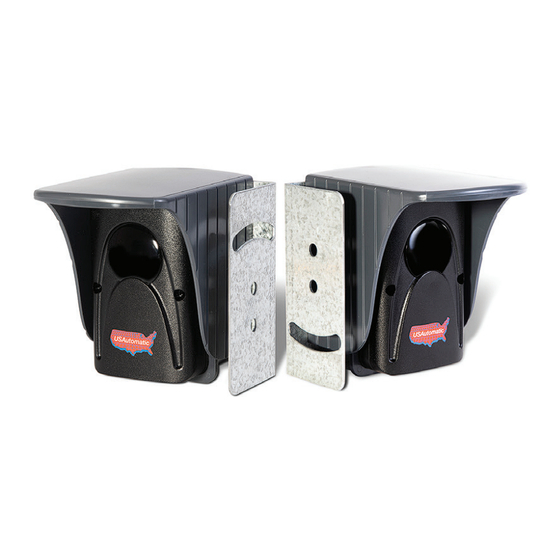
PHOTO EYE
Infrared Through Beam
#550011
INSTALLATION MANUAL
Read all instructions before installing this product.
Monitoring Method: N/C Contact
The infrared photo eyes are a People and Property safety device
intended for use with automatic gate operating systems. Swing gate
operators require at least one external monitored entrapment device
for gate operation and Slide gate operators require at least two
external monitored entrapment devices (one for each direction) for
gate operation per UL325 the standard for gate operator safety.
See gate operator installation manual.
The transmitter can be powered by two 3.6 vdc lithium batteries
(model - ER14505) or it may be hard-wired to the gate operator
control board. The expected battery life should exceed 1 year.
Rated range up to 42 feet / 13 meters in most conditions.
TECHNICAL SPECIFICATIONS
Power supply TX:
Battery voltage
Battery capacity
Battery type
Expected battery life
Power supply RX
Current consumption Transmitter
Current consumption Receiver
Double contact relay with serial exchange
RX output contacts
Max DC power on relay contacts
Max AC power on relay contacts
Operating temperature
Housing protection
Rated range
Dimensions with hood: WxHxD
PACKING LIST
ITEM
TX / TRANSMITTER
RX / RECEIVER
WIRING BOX
HOOD
MOUNTING BRACKETS
RUBBER SEAL
WIRING BOX MOUNTING SCREWS
#8 – 18 x ¾ inch Self tapping sheet metal (20mm length)
TX / RX MOUNTING SCREWS
#4 – 18 x ½ inch sheet metal (12.7mm length)
COVER MOUNTING SCREWS
#4 – ¼ inch black sheet metal (6.5mm length)
BATTERY 3.6v LITHIUM
www.USAutomaticGateOpeners.com | (800) 878-7829 | Sales@USAutomaticGateOpeners.com
1. INSTALLATION
Part
3.6V
2 x 3.6V
2.4Ah
ER14505
15 months
9 / 24 Vac/dc
400 μA
20 mA
yes
1 NO / 1 NC
24W / 48V
60 VA / 48 V
-4°F /+131°F
IP55
42 ft / 13 m
75 x 105 x 105 mm
2.95 x 4.13 x 4.13 in
Qty
1
1
2
2
2
2
8
8
4
2
NOTE: Mounting brackets should be installed to a rigid object to
prevent movement which could affect alignment and cause failures.
IMPORTANT: Conduit should be used from the control box to the
photo eye wiring box to protect wires from damage and moisture.
The wiring box has ½ inch knockouts located on the back and
bottom for the conduit connection. Do not remove the
TX-Transmitter wiring box knockout if using battery option.
1. Determine the best location for the photo eyes considering the
correct distance from the ground, conduit for wiring, location
of any irrigation system that might exist (avoid water spray) and
mounting surfaces are aligned with one another.
2. Install the mounting brackets and verify they are aligned with
each other. See figure 1.
3. Install the Transmitter and Receiver wiring box to the mounting
brackets using 4 screws and nuts.
4. Install the conduit to the receiver wiring box. If hardwired
installation install conduit for transmitter wiring box.
5. Install the receiver wires into the wiring box. If hardwired
installation install transmitter wires into the wiring box.
6. Route wire through the photo eye back plate.
7. Install the Transmitter and Receiver photo eye back plate to the
wiring box using the 4 sheet metal screws.
8. Connect wires per the wiring instructions.
9. Do not install covers at this time, this will be done after alignment
is complete.
Fig. 1 Mounting Surface Alignment
Fig. 2
Advertisement

Related Manuals for USAutomatic PHOTO EYE

Summary of Contents for USAutomatic PHOTO EYE
- Page 1 6. Route wire through the photo eye back plate. See gate operator installation manual. 7. Install the Transmitter and Receiver photo eye back plate to the The transmitter can be powered by two 3.6 vdc lithium batteries wiring box using the 4 sheet metal screws.
- Page 2 Wire size recommended 20 gauge stranded copper The RX / Receiver has a red LED which will illuminate when NOTE: Identify the type of installation the photo eye is being used for. power is applied to the RX / Receiver. When aligned with the TX / Transmitter, the red LED will go OFF and the green LED A.
Need help?
Do you have a question about the PHOTO EYE and is the answer not in the manual?
Questions and answers