Advertisement
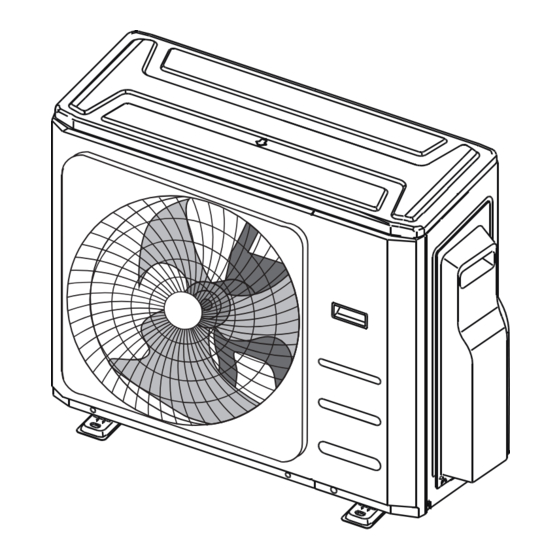
Multi Zone Outdoor
Installation Manual
IMPORTANT NOTE:
•
Read this manual carefully before installing
or operating your new air conditioning unit.
Make sure to save this manual for future
reference.
•
This manual only describes the installation
of outdoor unit. When installing the indoor
unit, refer to the installation manual of
indoor unit.
Advertisement
Table of Contents

Related Manuals for Blueridge BM18M23C


Summary of Contents for Blueridge BM18M23C
- Page 1 Multi Zone Outdoor Installation Manual IMPORTANT NOTE: • Read this manual carefully before installing or operating your new air conditioning unit. Make sure to save this manual for future reference. • This manual only describes the installation of outdoor unit. When installing the indoor unit, refer to the installation manual of indoor unit.
-
Page 2: Table Of Contents
Table of Contents Installation Manual Safety Precautions .........04 Accessories ..........05 Installation Overview ......06 Specifications ..........07 Outdoor Unit Installation ...... - Page 3 Refrigerant Piping Connection ......Wiring ..........Wiring Diagrams ......16 Refrigerant Handling ........Procedure ..............19 Refrigerant chart ...........21 Adding refrigerant ..........21 Test Run ..............Using the Automatic Wiring/Piping Correction Function ........
-
Page 4: Safety Precautions
Safety Precautions Read Safety Precautions Before Installation Incorrect installation due to ignoring instructions can cause serious damage or injury. WARNING CAUTION. The seriousness of potential damage or injuries is classified as either a Failure to observe a warning may result in death. The appliance must be installed in accordance with national regulations. -
Page 5: Accessories
Accessories The air conditioning system comes with the following accessories. Use all of the installation parts and accessories to install the air conditioner. Improper installation may result in water leakage, electrical shock and fire, or equipment failure. Name Shape Quantity Installation plate Plastic expansion sheath (depending on models) -
Page 6: Installation Overview
Installation Overview INSTALLATION ORDER Install the indoor unit Install the outdoor unit Connect the refrigerant (separate manual) (Page 09) pipes (Page 12) Evacuate the Connect the wires Perform a test run refrigeration system (Page 14) (Page 24) (Page 21) Revised 5/14/2020 ... -
Page 7: Specifications
Specifications Table 5.1 Number of units that can be used Connected units 1-5 units depending on model together Compressor stop/start frequency Stop time 3 min or more voltage fluctuation within ±10% of rated voltage Power source voltage voltage drop during start within ±15% of rated voltage interval unbalance within ±3% of rated voltage... -
Page 8: Outdoor Unit Installation
Outdoor Unit Installation The area must be free of combustible gases Outdoor Unit Installation Instructions and chemicals. The pipe length between the outdoor and Step 1: Select installation location. indoor unit may not exceed the maximum The outdoor unit should be installed in the allowable pipe length. - Page 9 BM36M23C 37.2" 16.5" 31.9" 26.5" 15.9" BM48M22C 37.5" 16.3" 52.5" 25" 15.9" BMHH18M22C 37.2" 16.5" 31.9" 26.5" 15.9" BM18M23C, BM27M23C, BM36M23C, BMHH18M22C, BMHH27M22C BMHH27M22C 37.2" 16.5" 31.9" 26.5" 15.9" BMHH36M22C 37.5" 16.3" 52.5" 25" 15.9" BMHH48M22C 37.5" 16.3" 52.5" 25"...
- Page 10 Notes On Drilling Hole In Wall NOTE: Be sure to maintain minimum clearanc- es for optimum operation as shown below. You must drill a hole in the wall for the refriger- ant piping, and the signal cable that will connect the indoor and outdoor units.
- Page 11 Refrigerant Piping Connection Step1: Cut pipes. Safety Precautions When preparing refrigerant pipes, take extra care to cut and flare them properly. This will ensure WARNING efficient operation and minimize the need for future maintenance. • All field piping must be completed by 1.
- Page 12 Pipe Table 7.1: Torque chart and flaring guide Reamer Pipe Flaring Flare dimension Flare shape gauge torque (A) (Unit: Inch) Point down Min. Max. 90 ° ± 4 1/4" 14 ft/ lbs 0.33 0.34 Fig 7.2 3/8" 18 ft/ lbs 0.52 0.53 1/2"...
- Page 13 Torque Requirements Outer Diameter of Pipe (inch) Tightening Torque (ft/lb) Add. Tightening Torque (ft/lb) 1/4" 11 ft/ lb 11.8 ft/ lb 3/8" 18.4 ft/ lb 19.18 ft/ lb 1/2" 25.8 ft/ lb 26.55 ft/ lb 5/8" 33.19 ft/ lb 34.67 ft/ lb NOTE: Use both a spanner and a torque NOTE ON MINIMUM BEND RADIUS wrench when connecting or disconnecting...
- Page 14 Wiring Safety Precautions CAUTION WARNING • Connect the outdoor wires before connecting the indoor wires. • Make sure you ground the unit. The • Be sure to disconnect the power supply grounding wire should be away from before working on the unit. gas pipes, water pipes, lightning rods, •...
- Page 15 Follow these instructions to prevent distortion 2. Remove the electric cover of the outdoor when the compressor starts: unit. If there is no cover on the outdoor unit, disassemble the bolts from the main- • The unit must be connected to the main out- tenance board and remove the protection let.
- Page 16 Wiring Diagrams CAUTION Connect the connective cables to the terminals, as identified, with their matching numbers on the terminal block of the indoor and outdoor units. For example, in the US models shown in the following diagram, Terminal 1(A) of the outdoor unit must connect with terminal 1 on the indoor unit.
- Page 17 BM27M three zone condenser 1 (B) 2 (B) 3 (B) 1 (C) 2 (C) 3 (C) 1 (A) 2 (A) 3 (A) 1 (B) 2 (B) 3 (B) 1 (C) 2 (C) 3 (C) 1 (A) 2 (A) 3 (A) 1 (B) 2 (B) 3 (B)
- Page 18 BM48M five zone condenser 1 (A) 2 (A) 3 (A) 1 (B) 2 (B) 3 (B) 1 (C) 2 (C) 3 (C) 1 (D) 2 (D) 3 (D) 1 (E) 2 (E) 3 (E) 1 2 3 1 2 3 1 2 3 1 2 3 1 2 3...
- Page 19 CAUTION After confirmation of the above conditions, follow these guidelines when performing wiring: • Always have an individual power circuit specifically for the air conditioner. • Always follow the circuit diagram posted on the inside of the control cover. • Screws fastening the wiring in the casing of electrical fittings may come loose during transportation.
-
Page 20: Refrigerant Handling
Refrigerant handling: Leak Test, Evacuation, and Refrigerant Charging Tools needed: Manifold Gauge • Dry nitrogen tank and regulator Compound gauge Pressure gauge • R410a manifold gauge set • 1/4" to 5/16" mini-split gauge adapter (yellowjacket) -76cmHg • Soap bubble solution sprayer High pressure valve •... - Page 21 8. Test Vacuum Let lineset sit in vacuum and 12. Record Pressure Start the unit in cooling- watch for rise in the gauge over 15 - 30 min- mode. Run for 10 minutes and monitor oper- utes. A slow rise is normal. If the gauge stays ating pressure reading.
-
Page 22: Adding Refrigerant
Table 9.1 Refrigerant Chart Directions: 1. Find your condenser model below. 2. Enter lineset length for each connected zone - calculate total. 3. Subtract your unit's pre-charge from the total. 4. If the result is negative, system is fully charged, do nothing. 5. -
Page 23: Test Run
Test Run Before Test Run Test Run Instructions 1. Open both the liquid and gas stop valves. A test run must be performed after the entire system has been completely installed. Confirm 2. Turn on the main power switch and allow the the following points before performing the test: unit to warm up. -
Page 24: Correction Function
Function of Automatic Wiring/Piping Correction Automatic Wiring/Piping Correction Function More recent models now feature automatic correction of wiring/piping errors. Press the "check switch" on the outdoor unit PCB board for 5 seconds until the LED displays "CE”, indicatomg that this function is working, Approximately 5-10 minutes after the switch is pressed, the "CE"... - Page 25 The design and specifications are subject to change without prior notice for product improvement. AlpineHomeAir.com...
Need help?
Do you have a question about the BM18M23C and is the answer not in the manual?
Questions and answers