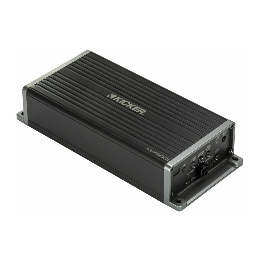
Kicker KEY500.1 Owner's Manual
Mono dsp amplifier
Hide thumbs
Also See for KEY500.1:
- Quick start manual (2 pages) ,
- Customer information card (2 pages) ,
- Owner's manual (60 pages)

Related Manuals for Kicker KEY500.1


Summary of Contents for Kicker KEY500.1
- Page 1 Owner’s Manual Manual del Propietario Manuel d’utilisation Benutzerhandbuch KEY500.1 Mono DSP Amplifier...
-
Page 2: Table Of Contents
Contents Overview ......3 Specifications ......4 Installation ...... 5 Mounting ....... 5 Wiring ........6 Operation ....... 9 Features ........ 9 KEY Auto Setup ....11 CXARC Remote Bass Installation ....14 Troubleshooting .... 15 Warranty ...... 16 English... -
Page 3: Overview
VENTILATION. SUBWOOFERS SHOULD BE MOUNTED WITH AT LEAST 1 INCH (2.5CM) CLEARANCE BETWEEN THE FRONT OF THE SPEAKER AND ANY SURFACE. KICKER PRODUCTS ARE CAPABLE OF PRODUCING SOUND LEVELS THAT CAN PERMANENTLY DAMAGE YOUR HEARING! TURNING UP A SYSTEM TO A LEVEL THAT HAS AUDIBLE DISTORTION IS MORE DAMAGING TO YOUR EARS THAN LISTENING TO AN UNDISTORTED SYSTEM AT THE SAME VOLUME LEVEL. -
Page 4: Specifications
Specifications Model: KEY500.1 RMS Power @ 14.4V, 4Ω mono, ≤ 1% THD+N 150 x 1 @ 14.4V, 2Ω mono, ≤ 1% THD+N 300 x 1 @ 14.4V, 1Ω mono, ≤ 1% THD+N 500 X 1 Length [in, cm] 8-1/8, 20.7 Height [in, cm] 1-11/16, 4.3... -
Page 5: Installation
Installation Mounting Choose a structurally sound location to mount your KICKER amplifier. Make sure there are no items behind the area where the screws will be driven. Choose a location that allows at least 4” (10cm) of open ventilation for the amplifier. If possible, mount the amplifier in the climate-controlled passenger compartment. -
Page 6: Wiring
Wiring Disconnect the vehicle’s battery to avoid an electrical short. Then connect the ground wire to the amplifier. Make the ground wire short, 24” (60cm) or less, and connect it to a paint-and-corrosion-free, solid, metal area of the vehicle’s chassis. Adding an additional ground wire of this same gauge (or larger) between the battery’s negative post and the vehicle chassis is recommended. - Page 7 The KEY amplifier is capable of using the wiring directly from your head unit, but for best results it is recommended you use power and ground wiring from the vehicle’s battery and chassis. KICKER recommends 8 gauge wire. External Fuse...
- Page 8 For multiple amplifier installations where distribution blocks are used, each amplifier should have its proper-rated fuse, or breaker, installed between the amplifier and the distribution block within eighteen inches of the block, or on the distribution block if it provides for fusing. The primary power wire should also be fused between the battery and distribution block, within eighteen inches of the battery’s positive terminal, with a fuse or breaker rated at least to the...
-
Page 9: Operation
DC OFFSET INPUT LEVEL − Features DC OFFSET: The KEY500.1 automatic turn-on mode uses DC Offset detection, which can be selected on the end panel. Using the DC Offset mode causes the REM wire to have +12V out for turning on additional amplifiers. DC Offset turn-on can only be used if speaker-level (hi-level) audio inputs are being used. - Page 10 It matches the output of the source unit to the input level of the amplifier and features Gain Matching to prevent clipping the input. Use the KEY500.1 Gain Match track from www.KICKER.com/test-tones...
-
Page 11: Key Auto Setup
Make sure active noise cancellation and active noise enhancement are disabled beforehand. You will need to load a source for the KEY500.1 test tracks from your head unit, whether CD, MP3, AUX, Bluetooth, USB etc. Uncompressed audio is recommended for best results, as this will ensure full amplitude across the frequency spectrum. - Page 12 30, turn it to 23). Press and hold the KEY button for 3 seconds until the gain match LED flashes quickly 3 times. Start the “Key500.1 Gain Match” track (The amplifier mutes its outputs during the Setup process so there will be no sound from the amplifier during setup).
- Page 13 KEY algorithm. Press and hold the KEY button for 5 seconds until the Gain Match LED slowly flashes, then release the button. Start the “Key500.1 Sweep” track. While the KEY algorithm is running the Gain match LED will flash slowly. This process will take about 1.5 minutes.
-
Page 14: Cxarc Remote Bass Installation
CXARC Remote Bass Installation Surface-mount the CXARC remote using the supplied screws. GAIN REMOTE MATCH BASS BASS HI PASS LO PASS BOOST 10-40Hz 40-160Hz 0-6dB GAIN 0-11 DC OFFSET INPUT LEVEL − back view Remote cable passes audio; do not run cable parallel to power wires. -
Page 15: Troubleshooting
There are Power (PWR) & Protection (PRT) LEDs on the side panel of your KICKER KEY series amplifier. Depending on the state of the amplifier and the vehicle’s charging system, the LEDs will glow either green or red. When the green LED is lit, this indicates the amplifier is turned on and no trouble exists. -
Page 16: Warranty
Should service be necessary under this warranty for any reason due to manufacturing defect or malfunction during the warranty period, KICKER will repair or replace (at its discretion) the defective merchandise with equivalent merchandise. Warranty replacements may have cosmetic scratches and blemishes. - Page 17 Service performed by anyone other than KICKER HOW LONG WILL IT TAKE? KICKER strives to maintain a goal of one week turnaround for all electronics (amplifiers, crossovers, equalizers, etc.) returns. Delays may be incurred if lack of replacement inventory or parts is encountered.
Need help?
Do you have a question about the KEY500.1 and is the answer not in the manual?
Questions and answers