Advertisement
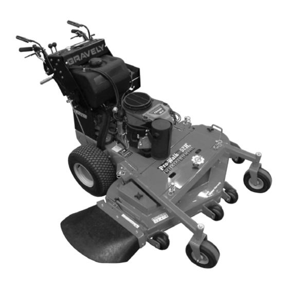
Pro-Walk Hydro
Owner/Operator Manual
Manuel Du Propriétaire/Utilisateur
Gasoline containing up to 10% ethanol (E10) or up to 10% MTBE (methyl tertiary butyl
ether) is acceptable for use in this machine.
The use of any gasoline exceeding 10% ethanol (E10) or 10% MTBE will void the product
warranty.
Il est possible d'utiliser de l'essence contenant jusqu'à 10% d'éthanol (E10) ou 10% de
MTBE (éther méthyl-tertiobutylique) sur cette machine.
L'utilisation d'une essence contenant plus de 10% d'éthanol (E10) ou de 10% de MTBE
annulent la garantie.
Serial No. 010000 and up
ENGLISH
FRANÇAIS
Models
988153 – 36HR PG
988154 – 48HE PG
988155 – 52HE PG
988156 – 36HR PS
988157 – 48HE PS
988158 – 52HE PS
988159 – 61HE PG
04296800B 12/11
Printed in USA
Advertisement
Table of Contents

Subscribe to Our Youtube Channel
Related Manuals for Gravely Pro-walk hydro 36HR PG


Summary of Contents for Gravely Pro-walk hydro 36HR PG
- Page 1 Pro-Walk Hydro Owner/Operator Manual Manuel Du Propriétaire/Utilisateur Models 988153 – 36HR PG 988154 – 48HE PG 988155 – 52HE PG 988156 – 36HR PS 988157 – 48HE PS 988158 – 52HE PS 988159 – 61HE PG Serial No. 010000 and up Gasoline containing up to 10% ethanol (E10) or up to 10% MTBE (methyl tertiary butyl ether) is acceptable for use in this machine.
-
Page 2: Table Of Contents
English may be obtained from your Before operation of unit, carefully and Dealer. Visit your dealer or completely read your manuals. The contents www.gravely.com for a list of will provide you with an understanding of languages available for your safety instructions and controls during normal equipment. - Page 3 Gravely authorized replacement part may adversely affect the performance, durability, or safety of this unit and may void the warranty. Gravely disclaims liability for any claims or damages, whether warranty, property damage, personal injury or death arising out of the use of unauthorized replacement parts.
-
Page 4: Safety
SAFETY Safety alert symbols and signal words are used on decals and in this manual. WARNING: This cutting unit is Read and understand all safety messages. capable of amputating hands and feet and throwing objects. Failure to observe the safety instructions DANGER: IMMINENTLY in the manuals and on decals HAZARDOUS SITUATION! If not... - Page 5 SAFETY DECALS AND LOCATIONS ALWAYS replace missing or damaged Safety Decals. Refer to Figure 2 and Figure 3 for Safety Decal locations. 988153, 54, 55 Never fill tank when engine is running, hot or unit is indoors. Never overfill fuel tank. Replace fuel cap securely and clean up spilled fuel.
- Page 6 988156, 57, 58, 59 Never fill tank when engine is running, hot or unit is indoors. Never overfill fuel tank. Replace fuel cap securely and clean up spilled fuel. 07731400E 07731400E Figure 3 GB - 6...
- Page 7 1. Danger! 5. Danger! Rotating Blades To avoid serious injury or death Read the operator’s manual. ROTATING BLADE! Keep hands and feet away. Keep children and others away Always stand clear of discharge from unit while operating. area. DO NOT direct discharge toward other people.
- Page 8 EMISSION CONTROL SYSTEM Read the entire Owner/Operator manual and other training material. If the operator or the This equipment and/or its engine may include mechanic cannot read the manual, it is the exhaust and evaporative emissions control owner’s responsibility to explain it to them. system components required to meet U.S.
- Page 9 Read, understand, and follow all instructions ALWAYS remove key to prevent unauthorized in the manual and on the machine before use. starting. Understand: DO NOT operate in reverse unless absolutely • How to operate all controls necessary. ALWAYS backup slowly. ALWAYS look down and behind, before and while •...
- Page 10 NEVER fill fuel tank when engine is running Poisonous battery fluid contains sulfuric acid or hot from operation. and its contact with skin, eyes, or clothing can cause severe burns. NEVER fill or drain fuel tank indoors. Explosive Gases! No flames, No sparks, No Replace fuel cap securely and clean up smoking near battery.
-
Page 11: Assembly
ASSEMBLY Check Engine Oil Level Check Tire Pressure 1. Remove dipstick from tube by unscrewing it. Wipe it clean. CAUTION: Avoid injury! 2. Install dipstick and allow cap to rest on Explosive separation of tire and the end of tube. Do not tighten the cap. rim parts is possible when they 3. -
Page 12: Controls And Features
CONTROLS AND FEATURES 988156, 57, 58, 59 Figure 5 1. Throttle Lever 10. Left Control/Operator Presence Control (OPC) 2. Choke Control 11. Control Lever 3. Fuel Cap 12. Speed Control Adjustment Lock 4. Hydraulic Reservoir Cap 13. Battery (988157, 58, 59) 5. - Page 13 988153, 54, 55 Figure 6 1. Operator Presence Control (OPC) Lever 9. Ignition Switch 2. Steering Lever Latch 10. Steering Control Lever 3. Parking Brake 11. Forward Speed Control Levers 4. Throttle Lever 12. Fuel Cap 5. Choke Control 13. Battery (988154, 55) 6.
- Page 14 NOTE: Refer to Figure 5 and Figure 6 for the Hour Meter location of the various controls. Measures the Throttle Lever number of hours the Changes engine speed. engine has been run. Fast (1) – Increases engine speed. Forward Speed Control Levers (988153, 54, 55) Half Throttle –...
-
Page 15: Operation
• Never mix oil and gasoline. operate unit. See your Gravely Dealer for NOTE: All gasoline is not the same. If the service. engine experiences starting or performance problems after using a new gasoline, switch Perform tests in a clear open area with no to a different fuel provider or fuel brand. - Page 16 Test Operator Presence Safety Test Safety Interlock System Interlock System (988153, 54, 55) (988156, 57, 58, 59) 1. Start engine. DANGER: SAFETY INTERLOCK SYSTEM FAILURE and improper 2. Move left control lever in to engage the operation of unit can result in death operator presence control switch.
- Page 17 (988156, 57, 58, 59) 1. Adjust the safety bar halfway back and tighten the left side lever for moderate mowing speed. 2. Engage parking brake. 3. Move PTO/clutch switch to OFF position. 4. Move throttle lever to half-speed position. (988153, 54, 55) NOTE: The engine will not start unless the speed control levers are in neutral, the parking brake is On and the Power Take Off...
- Page 18 OPERATING UNIT 988156, 57, 58, 59 CAUTION: Avoid injury! Learn the use of the control levers. Practice at half throttle until becoming proficient and comfortable with the operation of the unit. Do not move control levers from forward to reverse or reverse to forward position rapidly.
- Page 19 • To move straight forward; slowly release both steering levers to the full WARNING: Uncontrolled reverse outward position. travel can result in serious injury. Do not put steering levers into the reverse position unless you are prepared to operate in reverse. Speed control levers do not control reverse.
- Page 20 MOVING THE UNIT MANUALLY IMPORTANT: Transmission damage may occur if the unit is moved or towed incorrectly. • Move unit by hand only. CAUTION: With the bypass valves • Do not use another vehicle to move open, the unit will have unrestricted unit.
-
Page 21: Service And Adjustments
SERVICE AND ADJUSTMENTS ADJUSTING PARKING BRAKE 3. Rotate handle assembly up or down to preferred height. See Figure 8. 4. Reinstall thumb knobs. Parking brake must contact the rear wheel 5. Insert drive control rods into and prevent the unit from moving when corresponding holes in pump brackets engaged. - Page 22 ADJUST TRACKING 6. Drive unit forward, pushing both control levers (D) all the way to safety bar (A). (988156, 57, 58, 59) 7. Check unit tracking. 8. If unit does not drive in straight line, CAUTION: Avoid injury! Clear area adjustment is required.
- Page 23 ADJUST SENSITIVITY AND ADJUSTING TRANSMISSION SPEED NEUTRAL POSITION (988156, 57, 58, 59) (988156, 57, 58, 59) 1. Park unit safely. (See PARKING on page 19.) CAUTION: Avoid injury! Clear area 2. Raise drive wheels off the ground and of all bystanders before performing securely support the unit and block this service procedure.
- Page 24 ADJUST FORWARD TRACKING (988153, 54, 55) 1. Start engine and run unit at full throttle. 2. Slowly push both speed control levers forward to the desired speed setting. 3. Slowly release both steering levers (on handlebars) to the full outward (down) position.
- Page 25 STEERING CONTROL LEVER NEUTRAL ADJUSTMENT (988153, 54, 55) Check Neutral 1. Move speed control levers fully forward. 2. Depress steering control levers and engage latches. 3. Pull speed control levers back fully to neutral position. Steering latch levers should release. Verify that cross shaft cams are in contact with steering control rods.
- Page 26 ADJUSTING PUMP NEUTRAL POSITION See Figure 16. (988153, 54, 55) 1. Park unit safely. (See PARKING on page 19.) 2. Shut off unit. 3. Check steering control lever neutral position. See STEERING CONTROL LEVER NEUTRAL ADJUSTMENT on page 25. CAUTION: Avoid injury! Unit must be safely supported on jack stands before removing or installing wheels.
- Page 27 CUTTING HEIGHT ADJUSTMENT Controls Assembly Mounting WARNING: ALWAYS block wheels, Hardware engage parking brake and know all jack stands are strong, secure and will hold weight of unit during maintenance. Cutting height can be adjusted from 1-1/2 – 4-1/2 in. (38 – 114 mm) using the height of cut (HOC) rods and washers supplied with the Controls unit.
- Page 28 HOC Rod Position (Front Shown) Figure 19 To adjust cut height: 1. Using the grab handle (A), raise the deck until the desired hole in the HOC rod (C) is above the top of the frame (F) HOC Rod Position (Rear Shown) and washer (E).
- Page 29 ADDITIONAL CUTTING HEIGHT Desired Cut Number of Blade Bolt Height – Spacers on WARNING: Sharp edges can cut. Spindle In. (mm) Moving parts can cut off fingers or a hand. Wrap blade(s), wear sturdy 4.5 (114) Standard gloves and use extreme caution 4.75 (121) Short when servicing.
- Page 30 SERVICE LUBRICATION 988153, 56 Grease Use a general all-purpose grease with an NLGI grade No.2 rating. Lubrication Points • Apply grease to caster wheel bearings (A) on both sides. • Apply grease to front caster wheel pivot bushings (B) on both sides. 988154, 55, 57, 58, 59 Figure 25 Spray Lubricant...
- Page 31 Engine Oil 988153, 54, 55 Use oil viscosity based on the expected air temperature range during the period between oil changes. See the engine manual for correct specifications. Check Engine Oil Level See Figure 28. IMPORTANT: Avoid damage! Failure to check the oil level regularly could lead to serious engine problems if oil level is low: •...
- Page 32 IMPORTANT: Avoid damage! To prevent extensive engine wear or damage, always maintain the proper engine oil level. Never operate the engine with the oil level below the ADD mark or over the FULL mark. 11. Refer to the Engine Manual and add recommended oil in the correct amount.
- Page 33 Check and Clean Air Filter Elements 2. Disconnect the fuel hose from the outlet side (A) of the fuel filter, and drain gasoline into a properly marked CAUTION: Avoid injury! Touching container. hot surfaces can burn skin. The engine and components will be hot if the engine has been running.
- Page 34 NOTE: If necessary the filter guard (B) may MOWER SERVICE be removed for easier access to the filter. Adjusting Deck Belt Tension Loosen (do not remove) two hex bolts retaining the filter guard and slide guard off of (Figure 32) bolts.
- Page 35 Removing and Installing Mower Deck 988154, 55, 57, 58, 59 Drive Belt (988153, 56) 1. Park unit safely. (See PARKING on page 19.) 2. Remove mower deck center belt cover. 3. Loosen nyloc hex nut (A) on top of idler pulley (B) until belt will fit between pulley and belt guide.
- Page 36 Frame Mower deck shown with side discharge removed for illustration only. Figure 36 Removing Mower Blades See Figure 37. Bolt WARNING: Sharp edges can cut. Moving parts can cut off fingers or a Deck hand. Wrap blade(s), wear sturdy gloves and use extreme caution Figure 35 when servicing.
- Page 37 Replacing Mower Blades DO NOT Sharpen To This Pattern 1. Install the spacers (A), blades (B) and bolts (C) on the spindle shafts. 2. Secure blades with a wooden block to prevent blade rotation. 3. Tighten blade bolts to a torque of 120 lbf-ft (163 N•m).
- Page 38 3. Check balance. If blade is not balanced, heavy end of blade will drop. 4. Grind bevel of heavy end. Do not change blade bevel. Replacing Mower Spindle Bearings See Figure 41. 1. Park unit safely. (See PARKING on page 19.) NOTE: The mower blade can remain attached to the spindle shaft for this procedure but may be removed if preferred.
- Page 39 Replacing Mower Deck Idler Pulley TRACTION DRIVE BELT See Figure 42. NOTE: The Ogura electric clutch can be adjusted if the clutch starts to slip. (See NOTE: It is not necessary to remove spring CLUTCH ADJUSTMENT on page 40.) pressure to remove the idler pulley. 1.
- Page 40 CLUTCH ADJUSTMENT See Figure 45. If clutch fails to engage or disengage properly or begins to make abnormal noise, check the air gap adjustment at the three inspection B, C slots. To check: 1. Stop engine, remove key and wait for all hot parts to cool.
- Page 41 BATTERY SERVICE CAUTION: Avoid damage! The (988154, 55, 57, 58, 59) battery comes fully charged. If the unit is not used by the service expiration date indicated on the WARNING: Battery posts, battery, charge the battery. terminals and related accessories contain lead and lead NOTE: If charging is necessary, follow battery components, chemicals known to...
- Page 42 1. Park unit safely. (See PARKING on page 19.) Jump-Starting 2. Disconnect and remove battery. See Gravely does not recommend jump-starting Removing Battery on page 41. your unit. Jump-starting can damage engine 3. Wash battery with solution of four and electrical system components. See the tablespoons of baking soda to one Engine Manual for more detailed information.
- Page 43 ELECTRICAL SERVICE 988154, 55 Replacing Fuses IMPORTANT: Avoid damage! When replacing fuses – use only 20-amp fuses or you may damage the circuit. The unit is equipped with one 20-amp fuse to protect the charging circuit. The fuse is located under the control panel area to the left of the relays.
-
Page 44: Maintenance
MAINTENANCE MAINTENANCE SCHEDULE Every 160 Hours or Monthly (Whichever Comes First) IMPORTANT: Operating in extreme conditions may require more frequent service • Grease spindle bearings. intervals: • Check transmission oil level. • Engine components may become dirty • Spray lubricate mower deck idler or plugged when operating in extreme pulley pivots. -
Page 45: Storage
STORAGE Short Term Fuel System Do not spray the unit with water, especially Gasoline left in the fuel system for extended when the unit is warm from operation. Water periods without a stabilizer will deteriorate, can seep into bearings and damage them. resulting in gum deposits in the system. -
Page 46: Troubleshooting
TROUBLESHOOTING Engine Problem Probable Cause Engine Will Not Start or Is Hard to Control levers not in the neutral position. Start Neutral position switches not depressed fully. Ignition switch not in proper position. PTO engaged. Fuel tank empty See FILLING FUEL TANK on page 15.. Stale fuel. - Page 47 TROUBLESHOOTING Engine Engine Uses Too Much Oil Find and correct oil leaks. Incorrect engine oil. Plugged oil filter. Plugged air intake filter. Engine Backfires Through Muffler Throttle should be at low idle for several seconds before turning off unit. Leaking/damaged exhaust manifold gasket. High Fuel Consumption Improper type of fuel.
- Page 48 Blades dull, bent or unblalanced. Remove belt shields and check for debris on sheaves. Check sheaves for proper alignment or damage. See your Gravely dealer. Mower Blades Do Not Engage Mower deck drive belt slipping or broken. Spindle drive belt slipping or broken.
-
Page 49: Accessories
Pump bypass valves open. See MOVING THE UNIT MANUALLY on page 20. Pump drive belt damaged or worn. Wheel motor problems. See your Gravely dealer. Unit Creeps With Engine Needs control linkage adjustment. See ADJUSTING Running and Control Levers in a PUMP NEUTRAL POSITION on page 26. -
Page 50: Specifications
SPECIFICATIONS Model Number 988153 988154 988155 Description 36HR PG 48HE PG 52HE PG Engine Kawasaki Kawasaki FS600V FS481V Displacement – in. (cc) 36.8 (603) 36.8 (603) Starter Recoil Electric Fuel See Engine Manual Tank Capacity – Gallons (Liters) 5.8 (22) Hydraulic System Capacity Completely Dry System –... - Page 51 SPECIFICATIONS Model Number 988156 988157 988158 988159 Description 36HR PS 48HE PS 52HE PS 61HE PG Engine Kawasaki Kawasaki FS600V Kawasaki FS481V FS691V Displacement – in. (cc) 36.8 (603) 36.8 (603) 691 (42.2) Starter Recoil Electric Fuel See Engine Manual Tank Capacity –...
-
Page 52: Warranty
Commercial Mowing Equipment Limited Warranty Ariens Company (Ariens) warrants to the original purchaser that Ariens, Gravely and Countax brand products purchased on or after 1/1/2011 and designated or labeled commercial products by Ariens Company will be free from defects in material and workmanship for the time period noted in the chart below. Equipment put to personal use around a single household or residence is considered "Consumer Use";... - Page 53 Exclusions - Items Not Covered by This Warranty • Parts that are not genuine Ariens, Gravely or Countax service parts are not covered by this warranty and may void the warranty. • Damages resulting from the installation or use of any part, accessory, or attachment which is not approved by the Ariens Company for use with product(s) identified herein are not covered by this warranty.
- Page 54 California Evaporative Emission Control Warranty Statement YOUR WARRANTY RIGHTS AND OBLIGATIONS The California Air Resources Board and Ariens Company are pleased to explain the evaporative emission control system's warranty on your 2011 model year small off-road equipment. In California, new equipment that use small off-road engines must be designed, built, and equipped to meet the State's stringent anti-smog standards.
- Page 55 (c) The warranty on evaporative emissions-related parts will be interpreted as follows: (1) Any warranted part that is not scheduled for replacement as required maintenance in the written instructions must be warranted for the warranty period defined in subsection (b)(2). If any such part fails during the period of warranty coverage, it must be repaired or replaced by the Ariens Company.
- Page 56 GRAVELY 655 West Ryan Street Brillion, WI 54110 920-756-4688 Fax 920-756-4866 www.gravely.com WARNING The engine exhaust from this product contains chemicals known to the State of California to cause cancer, birth defects or other reproductive harm.
Need help?
Do you have a question about the Pro-walk hydro 36HR PG and is the answer not in the manual?
Questions and answers