
Related Manuals for rotork K-TORK Series


Summary of Contents for rotork K-TORK Series
- Page 1 K-TORK Range Installation & Maintenance Instructions High-performance quarter-turn / rotary pneumatic actuators Keeping the World Flowing...
-
Page 2: Table Of Contents
Contents Section Page Section Page Introduction Long-term storage Purpose of this manual Assembling actuator onto the valve Symbols General Preservation Mechanical considerations EU compliance / regulations Actuator removal from the valve Customer service Operation and use Health & safety Actuator operating description Appropriate usage Setting the actuator angular stroke Authorised personnel... -
Page 3: Introduction
The following instructions must be followed and integrated with your safety programme when installing and using Rotork Fluid Systems products: • Read and save all instructions prior to installing, operating and servicing this product. -
Page 4: Purpose Of This Manual
For any questions contact Rotork. designed, built and tested according to the K-TORK procedure and with the following regulations/directive: Rotork is not responsible for damage or injury caused by the failure to observe the instructions contained herein. • 2006/42/EC: Machinery Directive •... -
Page 5: Health & Safety
If in doubt, stop work and contact Rotork. described in the present manual. Rotork declines any responsibility for damage due to the following: • Failure to observe instructions •... -
Page 6: General Safety Notes
Health & Safety General safety notes No inspection or repair should be undertaken unless it conforms with the applicable hazardous Safety warnings contained herein and the instructions area certification requirements. It is strictly forbidden described in the other sections of this manual must be to remove the protection covers of the electrical observed to reduce health risks to the minimum and avoid components in potentially explosive environment,... -
Page 7: Residual Risks
Health & Safety Residual risks Residual risk: Protruding parts and sharp corners on the actuator can be a Residual risks imply potential hazards for the operator due to safety and/or health hazard for the staff, especially in case of incorrect work practices that are impossible to eliminate or falls. - Page 8 Residual risk: Safety risk for operators due to the blocking or clogging of the valve in the intermediate position during a manoeuvre. Prevention measure: In this case it is not allowed to remove the actuator from the valve. Contact Rotork.
- Page 9 Prevention measure: Prevention measure: The user must operate the actuator only using control devices Prior to any maintenance/setting operations, the operator supplies by Rotork. must check the operating drawings and if the TAG numbers correspond. Residual risk: Risk of intoxication or other health related problems during...
-
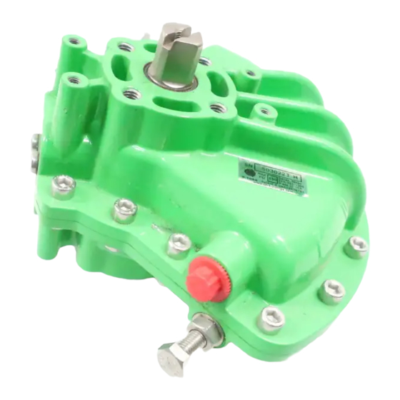
Page 10: Actuator Description
Actuator Description ACTUATOR DESCRIPTION The KT-XX-SR series actuators are pneumatic, single-acting spring-return actuators. These actuators can be assembled General description in a ‘spring to open’ or in a ‘spring to close’ configuration. The KT-XX-DA series actuators are pneumatic, double-acting The spring may be removed from the housing and flipped actuators specifically designed to provide efficiency and to reverse fail direction for flexibility and reducing stock reliability in heavy duty services. - Page 11 Actuator Description Actuator design characteristics are shown on the nameplate attached to the actuator. These actuators can be fitted with an emergency manual override suitable to operate the actuator in the event of fluid supply failure. This device can be of mechanical gear type operated by means of a handwheel.
-
Page 12: Checks To Be Carried Out Upon Delivery
If the actuator is seriously damaged, do not try to repair it or start it up. Please contact Rotork. Figure 3: KT-XX-DA/SR standard nameplate for units made in USA and China... -
Page 13: Handling & Lifting
Handling & Lifting HANDLING & LIFTING Actuator lifting Handling For KT-30-SR, KT-40-SR, KT-50-DA, KT-60-DA and KT-70-DA models, lift the actuator using appropriate chain or The actuator is supplied packed on pallets suitably for normal sling attached to the eyebolt lifting interface, situated on the handling. -
Page 14: Storage
If long-term storage is necessary, further operations must be carried out to maintain the actuator in good working Every Rotork actuator has been fully tested before leaving the condition, namely: factory to give years of trouble free operation, provided that it is correctly commissioned, installed and sealed. -
Page 15: 7 Assembling Actuator Onto The Valve
Rotork paint specification. Ensure that the the shafts, chances are you have an end-loading problem. coupling will slightly float up and down on the actuator and The assembly position of the actuator must be in accordance driven shafts. -
Page 16: Mechanical Considerations
Contact Rotork if in doubt. Ensure sufficient free space is available for the disassembly of • Ensure that all fasteners are adequately tightened to avoid the actuator from the valve. -
Page 17: 9 Operation And Use
Operation and Use OPERATION AND USE 9.2.1.2 Setting of the ‘open valve’ position (see Figure 7) ACTUATOR OPERATING DESCRIPTION Adjust the stop bolt as follows: Please refer to the operating diagram supplied for the specific • Pressurise the actuator from the second side until the actuator. -
Page 18: Fail To Open Actuator
Operation and Use 9.2.2 Fail to open actuator 9.2.2.2 Setting of the ‘close valve’ position (see Figure 7) 9.2.2.1 Setting of the ‘open valve’ position (see Figure 7) Adjust the stop bolt actuator, as follows: Adjust the stop bolt actuator, as follows: •... -
Page 19: Start-Up
Electrical connection can be performed as follows: manufactured. • Check that no power is present. Contact Rotork to check the compatibility of the • Remove the covers of the electric components. actuator with the chemical composition of the supply •... -
Page 20: Start-Up
Inspect actuator paint work for damage to ensure continued corrosion protection. Touch-up as required in accordance with the applicable paint specifications, please contact Rotork. Verify operation. The actuator should be cycled several times with the local and remote (if present) control. -
Page 21: Pneumatic Actuator Seals Replacement
Maintenance 11.1.2 Pneumatic actuator seals replacement Original spare parts and accessories can be ordered from your local Rotork office. When ordering spare parts, it is necessary to provide the following: 1. The actuator model and serial number from nameplate (see section 4.2). - Page 22 Separate the two case halves with a K-TORK tool model CP position (45° of rotation). Watch the vane indicator mark 1-4 or CP 5-6 (not included, consult Rotork). to know when the actuator is in mid position. c) Clean both case halves removing silicone rubber sealant e) Install the spring retainer.
- Page 23 Maintenance 11.1.2.5 Reassemble actuator 11.1.2.6 Mechanical travel stop removal a) Coat bearings and internal vane seal areas of the case With the actuator placed in a stable position, e.g. on a halves with grease supplied with the seal kits. workbench. b) Clean case flanges with isopropyl alcohol.
- Page 24 Maintenance Figure 10: Exploded view of K-TORK range actuator and spring assembly. Materials of Construction for Double-Acting and Spring-Return Actuators Item Description Material Integral Vane / Shaft ASTM A217 or 915 Cast Steel - Electroless Nickel Plated Vane Seal HNBR Vane Seal Expander 304 Stainless Spring Steel Vane Seal Side Plate Retainer...
- Page 25 Align the actuator shaft to the spring shaft, ensuring from Rotork. the vane is in the mid-position (45° of rotation). The The actuator may now be mounted to a valve. mount bolt holes of the spring housing should match the orientation of the actuator mount bolt holes.
-
Page 26: Troubleshooting
Examine the pipe work for blockages, crushed pipes or leakages. Pipe work blocked, crushed or leaking. Clear or replace as necessary. Fault of control accessories (If present). Contact Rotork. High valve torque or incorrect sizing. Consult the valve manufacturer’s documentation. For other problems, please contact Rotork. -
Page 27: Dismantling And Disposal
Rotork. Collect the grease and the oil during dismounting to avoid disposal of pollutants in the environment; the... - Page 28 As part of a process of on-going product development, Rotork reserves the right to amend and change specifications without prior notice. Published data may be subject to change. For the very latest version release, visit our website at www.rotork.com PUB097-008-00 The name Rotork is a registered trademark.
Need help?
Do you have a question about the K-TORK Series and is the answer not in the manual?
Questions and answers