Table of Contents
Advertisement
Quick Links
Advertisement
Table of Contents
Troubleshooting

Summary of Contents for COUSINS 3300-CTA
- Page 1 INSTRUCTION & MAINTENANCE MANUAL MODEL 3300-CTA CONVEYORIZED PLATFORM AUTOMATIC STRETCH-WRAPPING SYSTEM & OPTIONS COUSINS PACKAGING INC. 6450 Northam Drive, Mississauga, Ontario L4V 1H9 Canada Phone: (905) 678-6655 Fax: (905) 678-3429 www.cousinspackaging.com...
- Page 3 RAPID CHECKLIST Here is a simple and helpful procedure for starting the machine, but we also recommend that the manual be thoroughly reviewed by a qualified service technician MANUAL SECTION STEPS FOR REFERENCE Remove packaging materials and inspect for damage. Have the driver acknowledge any damage before signing acceptance. Section 4:2 IMPORTANT, you are responsible for any freight damage claims with the carrier. For a machine with an extended tower, refer to the manual for assembly Section 4:3 instructions. Install blue plastic cover to the top of the tower. Section 4:5 Item 1 Plug the machine to a standard 115V outlet. A 14 gauge extension cords may Section 4:6 be used temporarily. Manually jog the turntable and film carriage to check for binding or unusual Section 4:5 Item 8 noise. Manually lower and raise the film carriage to check for binding. The film Section 5:2:3:2 carriage MUST operate between its upper and lower limits Section 5:2:3:3 Load a roll of film and thread it according to the threading diagram located on the top of film carriage. Remember to restore power by pressing the “Power Section 6:2 On / Reset” push‐button on the control panel. Bring a test load to the machine… ...
- Page 5 TABLE OF CONTENTS BEFORE STARTING THE MACHINE............9 SPECIFIC CAUTIONS AND WARNINGS ..........11 MACHINE DESCRIPTION ................ 13 Machine Specifications ................ 14 Conveyor Specifications ..............15 INSTALLATION ..................17 Moving the Machine ................17 Unpacking and Inspection ..............17 Extended Tower Assembly (Optional) ..........18 4:3:1 Fold-Down Tower Assembly ............
- Page 6 5:2:5 Conveyor Manual Functions Screen (Optional) ......32 5:2:5:1 Conveyor Manual Reverse Button ..........32 5:2:6 Machine Settings Screens .............. 33 5:2:7 Wrap Count Settings Screen ............33 5:2:7:1 Top Wrap Revolutions Preset Display ......... 34 5:2:7:2 Base Wrap Revolutions Preset Display ........34 5:2:8 Photo-Eye Settings Screen ............
- Page 7 5:12 Auto Load Height Sensing Photo-Eye Adjustment ......50 5:13 Film Carriage Safety Switch ..............50 WRAPPING A LOAD ................53 Placing the Load onto the Turntable Conveyor ......... 53 Threading the Super Rapid Thread II™ Prestretch ......54 Attaching the Film to the Film Clamp ..........57 Starting the Wrap Cycle (Initial Set-up) ..........
- Page 8 10:0 TROUBLE-SHOOTING ................87 10:1 Trouble-shooting Operator Interface Fault Messages ....... 87 10:1:1 Film Fault ..................88 10:1:2 Film Carriage Safety Switch Tripped Fault ........89 10:1:3 Film Cut/Wipe Arm Watchdog Timer Fault ........90 10:1:4 Film Carriage Height Sensor Fault ..........91 10:1:5 Variable Frequency Drive Fault ............
- Page 9 BEFORE STARTING THE MACHINE Please refer to the following checklist before calling your Cousins Packaging distributor or the factory for start-up assistance. This will prevent confusion and additional expense during the start-up process. Check for any freight damage, (hidden or apparent) and if found report it to the carrier.
- Page 10 RUN ITS SAFE OPERATING RANGE, POTENTIALLY CAUSING SERIOUS DAMAGE! During the winter months, gear-reducer lubricants will thicken when exposed to cold weather during shipment. Allow the machine to warm up to room temperature for 8 hours (minimum) before attempting to operate the machine.
- Page 11 Our intention to provide only safe, quality packaging equipment to our customers is enhanced by our on-going Product Safety program. Cousins Packaging has no means of controlling the safe use of our equipment other than through the features designed and built into our machinery and the recommendations made in this manual.
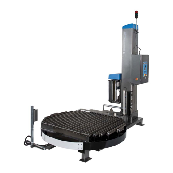
- Page 13 MACHINE DESCRIPTION The Model 3300-CTA Conveyorized Platform Automatic stretch-wrapping machine is a high-profile unit, designed to be loaded by fork-lift truck. machine operates on 115 volt 1 phase 20 amp electrical service. (Other voltages optional.) Model Version 3300-CTA1 shown...
- Page 14 Loading of 4,000 pounds turning and 12,000 pounds static. Standard design for pallet loads up to 48” square (68” Maximum Diagonal dimension), to 80” overall height. Film The 3300-CTA Conveyorized Platform Automatic accepts film up to 1.1 mils (28 microns) thick, wound on a standard 3” core...
- Page 15 with a roll diameter of 10” maximum and up to 20” maximum web height. Conveyor Specifications Capacity The conveyors are rated for 4,000 pounds dynamic per section. Maximum load size capacity is 48” long x 48” wide. Turntable Conveyor distance between frame rails (B.F.R.) is 53” and the effective roller width (E.R.W.) is 49.19”.
- Page 17 INSTALLATION Moving the Machine The 3300-CTA Conveyorized Platform Automatic is equipped with a structural tube base frame and can be fork-truck lifted from either front or rear. Simply insert the lift truck forks into the machine base frame tubes at either end, being careful not to hit the control panel if lifting from the tower side of the machine.
- Page 18 Extended Tower Assembly (Optional) Machines equipped with extended towers may be shipped in a “fold-down” condition. Assemble the tower to the machine as follows: 4:3:1 Fold-Down Tower Assembly Assemble the tower to the machine as follows: 1. Remove all packaging from the machine. 2.
- Page 19 11. Test for proper machine operation. 4:3:2 Tower Guard Removal / Installation To remove the front or rear tower guard: 1. Remove the four Button Head Socket screws securing the tower guard to the tower (two on top and two on the bottom). 2.
- Page 20 Install the gravity exit conveyor(s) on the appropriate side of the stretch wrap machine. After the conveyor(s) have been positioned, level the conveyor sections by adjusting the threaded conveyor feet. Once the conveyor section(s) have been leveled, secure the conveyor(s) to the floor using lag-bolts.
- Page 21 Turn on the Control Power by pulling out the red mushroom head E-Stop button on the control panel pressing the Power On / Reset push-button momentarily. Once the control power has been enabled the Film Cut / Wipe Arm, (if rotated inwards for shipment), will reverse to its retracted (home) position, clear of the turntable after a 5 second time-delay.
- Page 22 General Power Requirements Unless otherwise specified, the machine requires a 115 Volt, 1 Phase, 60 Hz., 20 Amp (unshared) line service. CAUTION! Power the system only from an adequately fused wall socket of the correct voltage. Do not use an extension cord as a severe line power drop may occur, resulting in damage to the electronic circuits! If it is necessary to use an extension cord temporarily, a #12 AWG (minimum)
- Page 23 SET-UP AND OPERATING PROCEDURES Operating Controls - Control Panel Door This section provides a description of the operator controls located on the exterior panel of the control enclosure. CAUTION CAUTION CAUTION CAUTION CAUTION CAUTION CAUTION CAUTION CAUTION CAUTION...
- Page 24 5:1:1 Main Disconnect Switch The Main Disconnect switch is used to disconnect the incoming power from the control and motor circuits. In the “O” (Off) position, power is disconnected. In the “I” (On) position power is connected. Holes in the operating handle of the Main Disconnect Switch allow for the installation of a padlock when the switch is turned to the “O”...
- Page 25 The button will remain illuminated until the Emergency Stop switch is pushed in or the Main Disconnect Switch is turned to the “O” (Off) position. WARNING! The interior of the control panel remains powered even when the power switch is turned OFF. ALWAYS unplug the machine before opening the control enclosure! 5:1:4 Wrap Cycle Start Push-Button This green push-button performs the following functions:...
- Page 26 5:1:8 Eject Load Push-Button (Basic 2-Station system only) The basic 3300-CTA system is a 2-station system consisting of the stretch wrap machine with powered turntable conveyor and a gravity exit conveyor. The basic system is equipped with an Eject Load push-button that can be used to discharge the load from the turntable onto the gravity conveyor.
- Page 27 5:2:5:1. 5:1:11 Outfeed Conveyor Jog Push-Button (Multi-Station System) 3300-CTA systems equipped with optional powered outfeed conveyor(s) will be provided with an Outfeed Conveyor Jog push-button for each outfeed conveyor section.
- Page 28 “screens” in an intuitive and operator-friendly arrangement. 5:2:1 Control Power Disabled Screen The Control Power Disabled Screen is displayed whenever power is connected and the 3300-CTA’s Master Control Relay (MCR) is disabled. Follow the displayed instructions on this screen to re-enable the control power.
- Page 29 Control Power Disabled Screen 5:2:2 Start-up Splash Screen The Start-up Splash Screen appears briefly after turning the control power on. Once the control power has been enabled the Start-up Screen will not reappear unless the control power has been disabled for a minimum of 1 minute. Start-up Splash Screen 5:2:3 Manual Functions #1 Screen The Manual Functions #1 Screen is the default screen that will appear after the...
- Page 30 Manual Functions Screen 5:2:3:1 Turntable Jog Button The TURNTABLE JOG button, when pressed, causes the turntable to rotate at slow speed. This function automatically stops when the button is released. 5:2:3:2 Film Carriage Raise Button Pressing the CARRIAGE RAISE button, causes the film carriage to ascend. This function automatically stops when the film carriage upper limit switch comes in contact with the upper limit striker, or when the button is released.
- Page 31 Manual Functions #2 Screen 5:2:4:1 Film Clamp Open / Close Button Pressing the CLAMP OPEN / CLOSE button, (if the machine is not performing a wrap cycle), toggles the Film Clamp Open Relay “on” or “off” depending upon its current status. If the Film Clamp Open Relay is de-energized with the film clamp in the ”closed”...
- Page 32 second pause will cause the Cut / Wipe Arm to retract until it reaches the Cut / Wipe Arm Retracted switch (7LS). This function is provided as a maintenance aid to assist in the adjustment and setting of the Cut / Wipe Arm position switch strikers.
- Page 33 will continue to run in the reverse direction), until all the Conveyor Jog push- buttons are released and the conveyors have come to a halt. 5:2:6 Machine Settings Screens The Machine Settings Screens are used to link to various other screens where machine presets and wrapping parameters can be accessed and adjusted.
- Page 34 Wrap Counter Settings Screen 5:2:7:1 Top Wrap Revolutions Preset Display The TOP WRAP REVOLUTIONS Preset Display is used to program the number of wrap revolutions that will be applied to the top of the load during the wrap cycle. To adjust the Top Wrap Counter Preset, press on the displayed TOP WRAP REVOLUTIONS numeric value.
- Page 35 cycle. To adjust the Base Wrap Counter Preset, press on the displayed BASE WRAP REVOLUTIONS numeric value. The Wrap Count Data Input keyboard screen will be displayed, where the desired value from “0” to “12” can be entered. Enter the new value on the keyboard and then press the ( ...
- Page 36 In the event that it becomes necessary to adjust the film carriage elevator height manually, (due to uneven load top layer, voids in the load or photo-eye malfunction), set this to the OFF state and adjust the upper limit switch striker position manually.
- Page 37 5:2:9 Clamp Open Height Screen The Clamp Open Height screen is used to preset the height above the film carriage bottom limit that the film carriage will pause at, to allow the film clamp to open during the wrap cycle. As the film carriage ascends, pulses from the carriage height pulse sensor are used to increment a counter in the PLC logic program.
- Page 38 Height numeric value. The Clamp Open Height Data Input keyboard screen will be displayed, where the desired value from “1” to “36” can be entered. Enter the new value on the keyboard and then press the ( ) button to accept it. If the new value is within the accepted range, the Clamp Open Height Screen will be re-displayed showing the new value.
- Page 39 5:2:10:1 Reduced Bottom Film Force Button The REDUCED BOTTOM FILM FORCE button is used to toggle the Reduced Bottom Film Force parameter ON or OFF. The REDUCED BOTTOM FILM FORCE button, when pressed, enables the Reduced Bottom Film Force parameter. Pressing the button again disables the Reduced Bottom Film Force parameter.
- Page 40 Low Load Settings Screen 5:2:11:1 Enable Low Load Wrap Button The ENABLE LOW LOAD WRAP MODE button is used to toggle the Low Load Wrap Mode parameter ON or OFF. The ENABLE LOW LOAD WRAP MODE button, when pressed, enables the Low Load Wrap Mode parameter.
- Page 41 If an automatic mode is selected, when a pallet load is presented to the infeed conveyor from a fork-lift truck, it is conveyed onto the turntable conveyor, after a brief time delay, (see section 5:2:11:2), if it is clear. If a pallet load is in the process of being wrapped, the incoming load will remain on the infeed conveyor until the turntable conveyor discharges the wrapped load and only then will it proceed onto the turntable conveyor.
- Page 42 Keyboard Screen #2 – Seconds Infeed Start Delay Data Input Operating Controls - Inside Control Panel WARNING! The interior of the control panel remains powered even when the power switch is pushed in to the STOP position. ALWAYS disconnect power before opening the control panel! 5:3:1 PLC Analog Trim-pots The Panasonic PLC used on this machine is equipped with two externally...
- Page 43 Panasonic Panasonic Panasonic Panasonic Trim-pot #V1 Decel (Delay) Timer 5:3:1:2 Analog Trim-pot #V1 – Decel (Delay) Timer The Decel (Delay) Timer is timer is an externally adjustable analog timer controlled by trim-pot #V1 located on the front cover of the PLC. This timer is used to delay the transition from Turntable Run Speed to Turntable Low Speed in the final revolution of the automatic wrap cycle.
- Page 44 5:4:1 Wireless Remote Start Push-Button Depending on how the machine is optionally equipped, this black push-button can perform one of two different functions: 5:4:1:1 Basic 2-stage System On basic 2-stage systems consisting of the wrapper and a gravity exit conveyor, after a load has been placed on the turntable, and after backing up from the machine clear of the load, pressing this black push-button, (providing the machine is not already performing a wrap cycle), starts the automatic wrap cycle.
- Page 45 5:5:1 Remote Start Push-Button Depending on how the machine is optionally equipped, this black push-button can perform one of two different functions: 5:5:1:1 Basic 2-stage System On basic 2-stage systems consisting of the wrapper and a gravity exit conveyor, pressing this black push-button, (providing the machine is not already performing a wrap cycle), starts the automatic wrap cycle.
- Page 46 Pulling on the rope actuates the Lanyard Start Switch, which starts the automatic wrap cycle or load infeed sequence. All machine functions will progress in proper order automatically without further input from the operator. Machine Status Indicator Beacon The Machine Status Indicator Beacon consists of a green and a red beacon light mounted to the top of the stretch wrap machine tower, and is used to indicate the status of the machine to the fork-lift truck operator.
- Page 47 low. This condition requires the attention of a technician at the machine to verify and correct the cause of the problem. The Cut/Wipe Arm Watchdog Timer has timed-out during a wrap cycle. This could be caused by the Film Cut/Wipe Arm becoming jammed against an improperly positioned load, of a protruding carton on the load.
- Page 48 Adjustments to these turntable speed settings are made by modifying the Preset Speed parameters on the turntable variable frequency drive (1VFD). (Refer to Section 9:7 and Section 15:0) WARNING! Adjustments to the Turntable VFD parameters should only be performed by a qualified technician! After making any adjustments, close the control panel and cycle the machine to observe the adjustment.
- Page 49 5:10 Film Carriage Speed Set-Up The 3300-CTA Conveyorized Platform Automatic Stretch-wrapper is equipped with independent speed controls for the film carriage raise and film carriage lower functions. 5:10:1 Carriage Raise Speed The film carriage raise speed is used to control the overlap between the layers of film while the film carriage is ascending.
- Page 50 Operator Interface Panel (HMI) Photo-eye Settings screen, (refer to Section 5:2:8:1). 5:13 Film Carriage Safety Switch The 3300-CTA Conveyorized Platform Automatic stretch wrap machine is equipped with a Film Carriage Descent Obstruction Plate and Carriage Safety Switch. The purpose of the Carriage Safety Switch is to disable the wrap cycle and carriage lower function in the event that the Descent Obstruction Plate is obstructed, (i.e.
- Page 51 To reset the machine after the film carriage safety switch has been tripped, manually raise the film carriage using the Film Carriage Raise button (refer to Section 5:2:3:2), or cycle the power by pressing the E-Stop button, then pulling it back out and pressing the Power On / Reset push-button to re-enable the control power.
- Page 53 WRAPPING A LOAD Placing the Load onto the Turntable Conveyor If the machine is equipped with an optional infeed conveyor, place the load to be wrapped onto the infeed conveyor. Observe the Machine Status Indictor Beacon, (refer to section 5:7). If the green Machine Ready Status Indicator Beacon is illuminated it is permissible to load the machine.
- Page 54 Threading the Super Rapid Thread II™ Prestretch Raise the film carriage to a comfortable height and place a roll of film on the film mandrel. Press in the Emergency Stop push-button and draw approximately four feet of material from the film roll. Twist the film into a rope and thread, as follows: Super Rapid Thread II ™...
- Page 55 FILM THREADING HAND WHEEL FILM THREADING HOOK SUPER RAPID THREAD II™ DOOR NIP / IDLER ROLLER Super Rapid Thread II™ FILM CARRIAGE Attaching the Film to the Film Threading Hook Referring to the threading diagram and the photograph above, turn the Film Threading Hand-Wheel in a clockwise rotation until the Film Threading Hook is located in the load position.
- Page 56 Threading the Film through the Film Carriage Referring to the photograph above, while supporting the rope of film toward the top of the rollers with one hand, turn the Film Threading Hand-Wheel in a clockwise rotation until the Film Threading Hook has drawn the film through the film carriage and the hook has returned to its starting location.
- Page 57 When control power has been reapplied, gently pull on the film tail. This action will cause the Dancer Roller to pivot and the machine will begin to dispense film, self-threading the film down across the full length of the Prestretch and Nip / Idler Rollers.
- Page 58 Wrap Cycle Sequence of Operation 6:5:1 Automatic Wrap Cycle Sequence Set the Top and Base wraps, to the desired values. Set the force to load and carriage speed controls to the desired levels. Ensure the film is secured in the film clamp.
- Page 59 delay, the film clamp will open, releasing the tail of film between the load and the film clamp. The film carriage then resumes descending. When the film carriage reaches the Carriage Bottom Limit switch (3LS) the film carriage stops descending and the base of the load is wrapped. Upon completion of the preset base wrap revolutions, (refer to Section 5:2:7:2), less one, the turntable begins the final revolution of the cycle.
- Page 60 A film fault has been detected. The turntable is running. The film carriage starts to descend, if it is not already at the stage of the wrap cycle where it is descending. The turntable reaches the Turntable Home Position sensor (1PX) at which time it begins the final revolution of the cycle.
- Page 61 wrapped load directly from the turntable conveyor, as damage to the machine may result. WARNING! Do not remove wrapped loads from the turntable. The machine is designed to only allow wrapped loads to be removed from gravity exit conveyor! If a load is present on the gravity exit conveyor and a wrapped load is present on the turntable, the Cut / Wipe Arm assembly will remain in the Wipe-down (fully extended) position, until the wrapped load on the gravity conveyor is removed...
- Page 63 REMEDIAL ADJUSTMENT Turntable Soft-Start Turntable Soft-Start, (or acceleration), is controlled by the turntable Variable Frequency Drive. Turntable start-up speed may be affected by a wide range of load weights and stability factors. If the load twists, distorts, or spills during the first few moments of turntable rotation, this may indicate that the Start Speed setting is too high, (refer to Section 5:9:1), or the acceleration time is set too low, (refer to Section 9:7).
- Page 64 Check all the roller surfaces that the film web passes over for any signs of cutting, imperfections or a build-up of film. WARNING! PINCH POINTS Be careful to keep hands, hair and loose clothing well clear of the polyurethane coated prestretch rollers and aluminum pinch rollers while power is applied! If the roll of film does not appear to have been damaged and there are...
- Page 65 Film Roping Roller The 3300-CTA Conveyorized Platform Automatic is equipped with a film-roping roller that will cause the bottom few inches of the film to be gathered in a roped fashion. Adjusting the roping roller height will provide a strengthening feature useful for holding difficult product and slip-sheets in place and for general reinforcement of the lower tiers of the load.
- Page 66 CAUTION! Ensure that at all times the upper limit switch striker is positioned ABOVE the film carriage limit lever arm. Failing to ensure this may result in the film carriage overrunning its allowable range of travel causing damage to the film carriage drive mechanism! Auto Load Height Photo-Eye False Signals The Auto Load Height Photo-eye uses an infrared beam reflected off the load...
- Page 67 Reinforcing Band Application In some cases it is desirable to add reinforcing bands of film between the top and bottom of the load as the film carriage is ascending or descending in order to further stabilize the load. If this is necessary it can be easily accomplished by pressing the PRESS TO REINFORCE WRAP button displayed on the Operator Interface Panel (HMI) status screen while the film carriage is raising or lowering during the wrap cycle, when the film carriage is at the desired height.
- Page 68 Film Carriage Paused Screen Pressing the PRESS HERE TO RESUME button that is displayed on the Operator Interface Panel (HMI) status screen while the film carriage is paused will allow the film carriage elevator to resume traveling. Alternately, after ten seconds the Carriage Pause function will self-cancel and the film carriage elevator will resume traveling without further input from the operator.
- Page 69 MAINTENANCE REQUIREMENTS Lubrication When operating in normal environments the machine will require periodic lubrication and maintenance as described in the following section. Use standard industrial lubricants on a regular basis in proportion to the usage of the machine and the cleanliness of the surroundings. Unless otherwise specified, lubricating oils and greases should be regular machine grade.
- Page 70 Item Operation Frequency Prestretch Chains Lubricate & Adjust Monthly Tension Prestretch Sprockets Inspect & Tighten Set- Monthly screws Prestretch Roller Bearings Inspect & Tighten Set- Monthly screws Conveyor Drive Gear-Reducer Change Oil Refer to Component Manufacturer’s specifications Conveyor Drive Sprocket Inspect &...
- Page 71 MAINTENANCE AND ADJUSTMENTS Film Carriage Lift Chain Adjustment To adjust the film carriage elevator chain, first raise the carriage to its halfway position and remove the tower chain guard. Visually inspect the film carriage elevator chain and shock-dampening spring. The chain should be taut on the bottom side where it attaches to the carriage, (about 3/4”...
- Page 72 The 3300-CTA Conveyorized Platform Automatic turntable fits over a compound drive axle and is driven through the engagement of the center shaft pin with the slotted turntable socket hub.
- Page 73 Remove the anti-rotation bolt securing the slip-ring anti-rotation bar to the base of the machine. Remove the hex socket flat-head bolt securing the turntable to the turntable center shaft, using a long shaft tee-handle hex key or equivalent tool inserted between the two center conveyor rollers. If no such tool is available, it may be necessary to first remove the two conveyor rollers in the center of the turntable conveyor to gain access to this bolt.
- Page 74 Remove the turntable conveyor chain guard and “break” the chains connecting the two center conveyor rollers of the turntable conveyor. The chain drive from the turntable conveyor drive gear-reducer located beneath the turntable to the conveyor rollers must also be disconnected. Remove the cotter pins from the conveyor roller hex axles on the two center rollers and remove them from the conveyor frame.
- Page 75 Turntable Support Wheels The 3300-CTA Conveyorized Platform Automatic turntable support wheels are rigid casters with bearings that may require periodic lubrication. Each caster is equipped with a grease fitting on the end of the wheel axle. Use a grease gun to apply grease to the wheel bearings as required.
- Page 76 ascend part way before stopping. Adjust the distance setting lower or higher accordingly to tune-out these problems. (Refer to Section 12:0 for specific details provided in the photo-eye manufacturer’s component literature.) The time-delay setting is typically set to a minimum value sufficient to prevent false tripping of the photo-eye output relay as the load rotates in front of the photo-eye.
- Page 77 Turntable Positive Alignment Set-Up and Adjustment If the turntable is not aligning correctly to the Turntable Home Position in the automatic wrap cycle, it may be necessary to adjust the Turntable Positive Alignment settings. The components related to the Turntable Positive Alignment feature include: ...
- Page 78 necessary for the turntable to reach the home position, but without coasting past. Keep in mind that the turntable must operate at the Slow Speed setting for long enough to lose all the inertia from the turntable before it reaches the Turntable Home Position. Traveling at the slow speed setting for the final 45°...
- Page 79 Raise the film carriage to a good working height and then remove power from the machine. Remove the prestretch carriage cover. If the prestretch motor is not shutting off completely when the dancer bar is in the retracted position, adjust the position of the Dancer Proximity Sensor closer to the cam by loosening the two jam nuts securing the proximity sensor to its mounting bracket.
- Page 80 9:11 Ni-Chrome Film Cutter Hot-Wire Installation The 3300-CTA Conveyorized Platform Automatic stretch-wrapper uses a length of Ni-Chrome resistance wire as a cutter for the film. WARNING! Film...
- Page 81 NI-CHROME FILM CUTTER BOTTOM DETAIL NI-CHROME WIRE BOTTOM MOUNTING BRACKET BOTTOM ANCHOR BOTTOM ANCHOR SET-SCREWS Loosen the two opposing set-screws in the bottom anchor and remove the Ni-Chrome wire. Remove the Ni-Chrome wire from the top insulator and disconnect it from the supply wire by loosening the four opposing set-screws in the top connector and unwrapping the tail of the Ni-Chrome wire from around the supply wire.
- Page 82 NI-CHROME FILM CUTTER SUPPLY WIRE TOP DETAIL CONNECTOR CONNECTOR SET-SCREWS INSULATOR TOP MOUNTING BRACKET INSULATOR SPRING NI-CHROME WIRE Insert the wire, top insulator and top connector into the top mounting bracket and then feed the wire through the vertical hole in the bottom anchor.
- Page 83 FILM CUT/WIPE ARM DETAIL CUT/WIPE ARM NI-CHROME POSITION SWITCHES FILM CUTTER HOT-WIRE 9LS (TOP) CUT/WIPE ARM 8LS (CENTER) 7LS (BOTTOM) CUT/WIPE ARM MOTOR FILM TAIL WIPER BRUSH CUT/WIPE ARM POSITION SWITCH ACTUATOR COLLARS CUT/WIPE ARM GEAR-REDUCER The Cut / Wipe Arm is designed to pivot in toward the package when the Turntable has aligned at the Turntable Home position during the wrap cycle, cutting the film between the load and the film clamp, and then wiping the cut-off tail of film against the load.
- Page 84 9:13 Film Carriage Safety Switch Adjustment The Model 3300-CTA Conveyorized Platform Automatic stretch-wrapping machine is equipped with a Descent Obstruction Plate. The Descent Obstruction plate is designed to “trip” the Film Carriage Safety Switch in the event that it becomes obstructed.
- Page 85 decrease the pre-load on the actuator arm. The following illustration depicts the nominal limit switch mounting location and actuator arm angle. The Film Carriage Safety Switch should be adjusted so that the switch actuates with minimal upward motion at each corner of the Descent Obstruction Plate. FILM CARRIAGE FRAME FILM CARRIAGE SAFETY SWITCH CARRIAGE FRAME BOTTOM GUSSET...
- Page 86 9:14 Prestretch Roller Cleaning Procedure Many cleaning agents can permanently damage the Prestretch Roller polyurethane coating. If cleaning of the polyurethane-coated prestretch rollers becomes necessary, the recommended procedure is as follows. Into a bucket of warm water, add a few drops common dish detergent and mix thoroughly.
- Page 87 10:0 TROUBLE-SHOOTING 10:1 Trouble-shooting Operator Interface Fault Messages 3300-CTA Conveyorized Platform Automatic stretch wrap machines are programmed to be able to detect a number of different fault conditions and display corresponding fault messages and diagnostic information on the Operator Interface Panel, also referred to as an HMI (Human-Machine Interface).
- Page 88 10:1:1 Film Fault A film fault is caused by a loss of film tension during the wrap cycle. A film fault will not be registered until the second turntable revolution has been completed, and cannot be detected after the machines goes into deceleration mode in the final revolution of the wrap cycle.
- Page 89 10:1:2 Film Carriage Safety Switch Tripped Fault 3300-CTA Conveyorized Platform Automatic stretch wrap machines are equipped with a Descent Obstruction Plate and Film Carriage Safety Switch (4LS) located beneath the Film Carriage. The purpose of the Film Carriage Safety Switch (4LS) is to disable the wrap cycle and the film carriage descent function in the event that the Descent Obstruction Plate becomes obstructed, (i.e.
- Page 90 10:1:3 Film Cut/Wipe Arm Watchdog Timer Fault 3300-CTA Conveyorized Platform Automatic stretch wrap machines are equipped with a motorized Film Cut/Wipe Arm that is used to move the film to a position where the film clamp can grip it, cut the film, and then brush the film tail against the load.
- Page 91 10:1:4 Film Carriage Height Sensor Fault If the Film Carriage Height Pulse sensor (5PX) remains either on or off for longer than preset watchdog times (approximately 3 to 5 seconds) during operation of the film carriage elevator function in a Wrap Cycle or by the A-Arm Manual Lower function, the sensor is presumed to be out of adjustment or defective, or the film carriage elevator is not physically moving, and this fault condition will be triggered.
- Page 92 10:1:5 Variable Frequency Drive Fault 3300-CTA Conveyorized Platform Automatic stretch wrap machines use minimum five (depending on options) variable frequency drives to control the motors on the machine – one for the Turntable motor (1VFD), one for the Film Carriage Elevator motor (2VFD), one for the Prestretch film dispenser motor (3VFD), one for the Film Cut/Wipe Arm motor, and one for the Turntable Conveyor motor (5VFD).
- Page 93 10:1:6 Wrap Cycle Watchdog Timer Fault All the while the wrap cycle is in progress (except during a Cycle Pause request or a Film Carriage Pause request), the Wrap Cycle Watchdog timer in the PLC records the elapsed cycle time. If the elapsed cycle time reaches the preset value in the timer, the wrap cycle will immediately be aborted and the message screens below will be displayed.
- Page 94 10:2 Trouble-Shooting Guide In the event of a machine malfunction, the suggestions listed in this section will assist in determining the cause of a failure and possible remedies. Many of the corrective actions recommended here require technical ability. Only qualified and fully trained personnel should perform the corrective actions listed in this trouble-shooting guide! PROBLEM DETECTED POSSIBLE CAUSE...
- Page 95 PROBLEM DETECTED POSSIBLE CAUSE CORRECTIVE ACTION HMI (Operator Interface HMI (Operator Interface Reconnect HMI cable Panel) screen flickers or Panel) cable connector is connector and ensure that it continually displays start-up loose is securely latched in place. (Initializing) screen PLC is not in RUN mode Set switch on face of PLC to RUN mode Machine Busy (red) status...
- Page 96 PROBLEM DETECTED POSSIBLE CAUSE CORRECTIVE ACTION Turntable does not run in Turntable Variable Frequency Turn off the power and wait wrap cycle or with Turntable Drive (1VFD) faulted 10 seconds, then reset the Jog Rotate button power. If the fault condition …continued…...
- Page 97 PROBLEM DETECTED POSSIBLE CAUSE CORRECTIVE ACTION Turntable runs too slowly or Turntable Speed setting is too Increase the Turntable Speed Turntable stalls when setting. (Refer to section wrapping a heavy load 5:9:2) Load weight exceeds Do not wrap loads that capacity of the machine exceed the rated weight capacity of the machine!
- Page 98 PROBLEM DETECTED POSSIBLE CAUSE CORRECTIVE ACTION Film Carriage will not raise or Carriage jammed Move carriage from side to lower …continued… side and back and forth by hand. There should be some play between the carriage guide wheels and the bars on which they run.
- Page 99 PROBLEM DETECTED POSSIBLE CAUSE CORRECTIVE ACTION Film Carriage raises and Carriage Speed setting(s) are Increase the Carriage Speed lowers too slowly too low setting(s). (Refer to sections 5:1:5 & 5:1:6) Film Carriage raises and Carriage Speed setting(s) are Decrease the Carriage Speed lowers too fast and / or speed too fast setting(s).
- Page 100 PROBLEM DETECTED POSSIBLE CAUSE CORRECTIVE ACTION Prestretch will not run Dancer Proximity Sensor Check for 24 Volts DC across …continued… Defective terminals #7 & #9 on control panel terminal strip with Dancer Bar retracted & Force to Load pot set at zero Then, check for 0 Volts DC across terminals #8 &...
- Page 101 PROBLEM DETECTED POSSIBLE CAUSE CORRECTIVE ACTION Prestretch runs too fast and / Dancer Proximity Sensor and Adjust distance between or speed cannot be varied / or Target Cam incorrectly Dancer Proximity Sensor and adjusted cam. Adjust position of cam if necessary.
- Page 102 PROBLEM DETECTED POSSIBLE CAUSE CORRECTIVE ACTION Prestretch continues to run Dancer Proximity Sensor and Adjust distance between after the film has been cut / or Target Cam incorrectly Dancer Proximity Sensor and …continued… adjusted cam. Adjust position of cam if necessary.
- Page 103 PROBLEM DETECTED POSSIBLE CAUSE CORRECTIVE ACTION Film Cut / Wipe arm does not Cut / Wipe Arm jammed Check for signs of operate mechanical binding or …continued… jamming. Ensure cut/wipe arm is clear of film clamp arms. Cut / Wipe Arm shaft key or If motor appears to be motor key missing running, but cut/wipe arm...
- Page 104 PROBLEM DETECTED POSSIBLE CAUSE CORRECTIVE ACTION Film is not cut during cycle Hot-wire cutter is missing the Adjust Cut Position switch …continued… film due to incorrect (8LS) Actuator Collar position adjustment of the Cut/Wipe or Cut/Wipe arm alignment as Arm Cut Position switch (8LS) necessary.
- Page 105 PROBLEM DETECTED POSSIBLE CAUSE CORRECTIVE ACTION Wrap Cycle not Sequencing PLC Hardware Problem Verify that all PLC hardware Properly PLC Software Logic Program is operational. problem Verify correct PLC Software Logic Program is installed and that PLC is in RUN mode.
- Page 106 PROBLEM DETECTED POSSIBLE CAUSE CORRECTIVE ACTION Film Carriage does not lower The film carriage Descent Raise the film carriage to a during wrap cycle Obstruction Plate is jammed good working height and …continued… in the up position move film carriage Descent Obstruction Plate from side to side and back and forth by hand, to allow the plate to...
- Page 107 11:0 PARTS LISTS The parts lists shown in this section are for the end-user’s reference in identifying components of the machine. When a malfunction is traced to a failed component, the part number for that component will aid in the procurement of a replacement part.
- Page 109 Machine Serial Number: 270517-33-12869 Machine Assembly Dwg: G3300-242-00 R0 LOCATION QTY. UN. SP COUSINS P/N DESCRIPTION DWG ITEM # 3300-CTA MACHINE BASE & TURNTABLE DRIVE MECHANICAL ASSEMBLY DWG. #G3300-230-01-00 Machine Base C4535 3300-CTA Base Weldment for 20" Pass-Line 1.1.15 Turntable Support Wheels Y W101-4 Caster 6”...
- Page 111 Section 11 LOCATION QTY. UN. SP COUSINS P/N DESCRIPTION DWG ITEM # C3360 Control Panel Mounting Frame Weldment for Control Panel Mounting Control Panel 42" x 30" Size Frame Frame Bracket C3361 Control Panel Frame Mounting Bracket FILM ROPING ROLLER ASSEMBLY - G5700-023-00 (G143)
- Page 113 Section 11 LOCATION QTY. UN. SP COUSINS P/N DESCRIPTION DWG ITEM # 20.C TURNTABLE LOAD POSITIONING PHOTO-EYE MOUNT C1542 20C.1 Photo-Eye Support C1543 Support Weldment 20C.2 Photo-Eye Support F757 Unistrut Bracket 20C.3 Photo-Eye Support F114 Photo-Eye Guard 20C.4 Photo-Eye Support R326-32 Unistrut Channel-32"...
- Page 115 Section 11 LOCATION QTY. UN. SP COUSINS P/N DESCRIPTION DWG ITEM # SWITCH SERIES STD. TOWER & FILM CARRIAGE LIFT DRIVE - MECHANICAL ASS'Y DWG. #G2700-050-00 R3 Tower Structure G2700-050-01-00- Standard 80" Tower Frame Weldment 2.2A Film Carriage Lift Gear-Reducer...
- Page 117 Section 11 LOCATION QTY. UN. SP COUSINS P/N DESCRIPTION DWG ITEM # TURNTABLE CONVEYOR ASSEMBLY 72" DIA. FLOW THROUGH DESIGN - 30 F.P.M. DWG. #G4900-113-00 R1 Turntable Weldment G4900-113-01-00 Turntable Weldment - Universal Flow, 72" Dia. For In-Level Transition Rollers...
- Page 119 Section 11 LOCATION QTY. UN. SP COUSINS P/N DESCRIPTION DWG ITEM # FILM CLAMP MECHANICAL ASSEMBLY - G138 DWG. #G5900-019-00-R5 Film Clamp Mounting Plate C1073-R7 Film Clamp Mounting Plate Film Clamp Linear Actuator C661 Actuator Anchor Plate Mount Film Clamp Linear Actuator...
- Page 121 Section 11 LOCATION QTY. UN. SP COUSINS P/N DESCRIPTION DWG ITEM # SUPER RAPID THREAD II 20" PRESTRETCH - MECHANICAL ASSEMBLY - G2900-115-00-R3 Carriage Weldment G2900-115-01-00 Super Rapid Thread II 20" Prestretch - Carriage Frame Weldment 5.41 Prestretch Motor Prestretch Motor Flange Spacer Washer 5.2B...
- Page 123 Section 11 LOCATION QTY. UN. SP COUSINS P/N DESCRIPTION DWG ITEM # 5.89 Anti-Back-Rotation One-Way B315 One-Way Bearing 20mm ID x 47mm OD x Bearing 14mm Wide c/w Inner Race Keyway, Seals both sides 5.88 Anti-Back-Rotation One-Way F2461 One-Way Bearing Housing Retainer Angle Bearing 5.86...
- Page 125 Section 11 LOCATION QTY. UN. SP COUSINS P/N DESCRIPTION DWG ITEM # 5.72 Dancer Proximity Sensor Refer to Electrical portion of this Material List, under "Electrical Controls on Film Carriage" 5.33 Front Diverter Roller Mtg. F2094-R5 Film Diverting Rollers Mounting Bracket 5.17...
- Page 127 Section 11 LOCATION QTY. UN. SP COUSINS P/N DESCRIPTION DWG ITEM # 5.42.10 Film Threading Idler Sprocket H1011 Nylon Round Spacer 1/2" ID x 3/4" OD x 3/8" on Nip Roller Axle Thick 5.42.13 Film Threading Idler Sprocket H776 Lock Washer 5/16" (M8) Plated on Nip Roller Axle 5.42.14 Film Threading Idler Sprocket...
- Page 129 Section 11 LOCATION QTY. UN. SP COUSINS P/N DESCRIPTION DWG ITEM # CUT/WIPE DEVICE FOR 20" FILM - MECHANICAL ASSEMBLY DWG. #G6900-039-00-R2 6.27C Cut/Wipe Device Motor Y A461 Motor Type 71L/4 IEC C105, 0.37kW - 1/2 HP 230/460 Volt 3 Phase 60 Hz. 1750 RPM TEFC UL/cCSAus, IP55 6.28E...
- Page 131 Section 11 LOCATION QTY. UN. SP COUSINS P/N DESCRIPTION DWG ITEM # ELECTRICAL CONTROLS DWG. #ED3300-148, #EP3300-148, #ES3300-148 Control Panel Enclosure & Exterior Control Panel Enclosure C3360 Control Panel Mounting Frame Weldment 42" x 30" Panel For Model HP-SW Conveyorized...
- Page 133 Section 11 LOCATION QTY. UN. SP COUSINS P/N DESCRIPTION DWG ITEM # Infeed Conveyor Jog Push- E1937 Contact Block c/w Mounting Base 1 x N.O. Button Outfeed Conveyor Jog Push- Y E1956 Push-Button Head Black Flush Momentary Button Outfeed Conveyor Jog Push- E1937 Contact Block c/w Mounting Base 1 x N.O.
- Page 135 Section 11 LOCATION QTY. UN. SP COUSINS P/N DESCRIPTION DWG ITEM # 1VFD, Y E2328 Altivar 312 AC Variable Speed Drive 380-500 Volt 3 Phase 50/60 Hz Input - 3/4 HP 460 Volt 3 Phase Output c/w Heatsink 2-VFD, 3-VFD, 5-VFD, 6-VFD, 7-...
- Page 137 Section 11 LOCATION QTY. UN. SP COUSINS P/N DESCRIPTION DWG ITEM # Machine Status Indicator Beacon Light Machine Busy-Fault (Red) / E2264 Surface Mount Beacon - Red/Green "Spider" Ready (Grn) Beacon Light Dome Lens Surface Mount Indicator c/w 5 Mtr.
- Page 139 Liquidtight Conduit Straight - Plastic 3/4" Hub 1JB - Machine Base Junction E575-P Panel Enclosure NEMA 12 - 8” x 6” x 4” Deep - Painted Cousins Gun-Metal Grey 1JB Terminal Strip E470 Terminal Block 6mm Beige 1JB Terminal Strip...
- Page 141 LX3000, 3200, 3300 Machines) Position (Top) Slip-Ring Assembly E2278 Slip-Ring Assembly 6 Conductor 480V 7.5A Rated c/w 4.0" Bore (For 3300-CTA c/w 3 Phase T/T CNVR. Motor) 6JB - Turntable Junction Box E1347 Diecast Aluminum Alloy Flanged Box Type 4.33" x 3.23" x 1.58"...
- Page 143 Section 11 LOCATION QTY. UN. SP COUSINS P/N DESCRIPTION DWG ITEM # 1TRANS - Hot-Wire E2355 Transformer Single Phase Enclosed 350VA Transformer 480V Primary 24V Secondary Electrical Controls on Infeed Conveyor 7JB -Infeed Conveyor Junction E575-P Panel Enclosure NEMA 12 - 8” x 6” x 4” Deep...
- Page 145 Section 11 LOCATION QTY. UN. SP COUSINS P/N DESCRIPTION DWG ITEM # Electrical Controls on Outfeed Conveyor 8JB -Outfeed Conveyor E575-P Panel Enclosure NEMA 12 - 8” x 6” x 4” Deep Junction Box 8JB -Outfeed Conveyor C701 Conveyor Junction Box Mounting Bracket...
- Page 147 12:0...
- Page 149 Thank you very much for using SUNX products. Please MOUNTING read this Instruction Manual carefully and thoroughly for the correct and optimum use of this product. Kindly keep The tightening torque should be 0.8N m or less. this manual in a convenient place for quick reference. INSTRUCTION MANUAL Never use this product as a sensing M5 (length 32mm)
- Page 150 If pressure terminals are to be used, affix the connect- BGS/FGS FUNCTION STABILITY INDICATOR ed pressure terminals to a terminal (M3.5 screw). (DC-voltage type only) Dimensions of the suitable crimp terminals Since the EQ-500 series use a 2-segment photo- diode as its receiving element, and sensing is done (Unit: mm) This sensor incorporates BGS/FGS function.
- Page 151 WL2000 photoelectric reflex sensor Rugged plastic housing Power supply reverse polarity protected Standard mounting for your existing applications Polarizing filters prevent false readings on reflective surfaces Wide range supply voltage Red light for easy alignment Signal strength indicator Cable or Mini quick disconnect versions Crosstalk immunity Signal Strength Indicator (Red) Power Indicator (Green)
- Page 152 WL2000 p h o t o e l e c t r i c r e f l e x s e n s o r WL 2000 -R1302 -R1312 -R1322 -R5300 -R5310 -R5320 Part Number 7 023 050 7 023 051 7 023 052 7 023 053 7 023 054...
- Page 155 +++++++++++++++++--tm XS1-L / XS2-L / XS1-N / XS2-N Listing and Certification : Inductive proximity sensors XS1-L XS2-L Applicable on proximity switches bearing the Détecteurs de proximité inductifs UL and CSA marks only. Enclosure : Type 12,4X indoor use only Induktive Näherungsschalter For connector version, a suitable UL and CSA Detectores de proximidad inductivos Approved connector must be used...
- Page 156 +++++++++++++++++--tm XZ-CP / XZ-CC Machine cabling accessories XS•-L/N•••••• Constituants de câblage machine Zubehör für Maschinen- Anschlußtechnik Contituyentes de conexionado Accessori di cablaggio Constituintes de cablagem Dimensions Ø8 Ø10 M8x1 16,5 Encombrements Abmessungen Dimensiones Dimensioni d’ingombro Altravancamentos M8x1 PvR L = 2 m. XZ-CP0166L2 XZ-CP0266L2 XZ-CP0566L2...
- Page 157 VL (AZ8) COMPACT SIZE LIMIT SWITCHES Limit Switches A compact and accurate vertical limit switch. Switches with indicator lamp available for convenient maintenance; either a neon AC powered lamp or an LED DC powered lamp. of the lamp holder attachment, it is Inner construction possible to display both lights during Cover...
- Page 158 VL (AZ8) PRODUCT TYPE 1. Standard type Actuator Part No. Push plunger AZ8111 Roller plunger AZ8112 Cross roller plunger AZ8122 Roller arm AZ8104 Adjustable roller arm AZ8108 Adjustable rod AZ8107 Flexible rod AZ8166 Spring wire AZ8169 Remote wire control plunger AZ8181 Note) When ordering an overseas-specified product,refer to the Overseas Standards given below.
- Page 159 VL (AZ8) SPECIFICATIONS 1. Contact Rating 1) Standard type 2) Type with indicator Load Resistive load Inductive load Resistive load Inductive load Rated control Types (cos φ ]1) (cos φ ]0.4) (cos φ ]1) (cos φ ]0.4) Rated control voltage voltage 125V AC 125V AC...
- Page 160 VL (AZ8) DIMENSIONS inch 10.2 10.2 .276 dia. .402 .402 stainless steel plunger General .118 PT 1.5max • Push plunger type tolerance: +0.2 2-4.1 dia. Standard type ±0.4 26.5 mounting holes .157 .157 1.043 2-M5 ( P=0.8 ) tapped M3 6 2-M5 ( P=0.8 ) 20.4±0.3 cover screw...
- Page 161 VL (AZ8) • Adjustable rod type inch ( 44.9 ) ( 44.9 ) ( 1.768 ) ( 1.768 ) .217 36.3±0.8 36.3±0.8 Standard type 1.429±.031 1.429±.031 General .102 dia. rod ( Roller can be rotated tolerance: and locked in any position through 360°...
- Page 162 VL (AZ8) • Spring wire type General tolerance: ±0.4 ±.016 (Should be used with less than 50mm 1.969inch of T.T.) Standard type 10.2 10.2 PT 30 max .402 .402 1.2 dia. 1.2 dia. .047 stainless .047 stainless steel wire steel wire 51.5 2.028 100±1.5...
- Page 163 VL (AZ8) OPTION inch (A set of mounting hex. VL Conduit Adapter t=7 max. socket screws is supplied.) .276 AZ8801 • Applicable wire 13/64 ( Same as with the VL limit switch ) Electric wire name Finished outside diameter Vinyl cabtire cord (VCTF) 8.7 to 11 dia.
- Page 164 VL (AZ8) WIRING Cable treatment inch Applicable fasten terminal Ordinary termi- -Insulation distance more than Max. 6.4 .252 Max. 6.4 .252 Max. 6.4 .252 3.0 to 3.7 dia. N.C. use N.O. use 6.4mm .252inch for wiring and live .118 to .146 .354 parts .354...
- Page 165 Product data sheet XCSDMC7902 Characteristics coded magnetic switch - XCS-DMC - cable 2 m - 1 NO + 1 NO, 1 NO staggered Main Range of product Preventa Safety detection Product or component Coded magnetic switch type Component name XCSDMC Electrical connection Pre-cabled Cable length...
- Page 166 Shock resistance 30 gn 11 ms IEC 60068-2-27 Sensitivity to magnetic fields ≥ 0,3 mT Class of protection against electric shock Class II IEC 60536 IP degree of protection IP66 IEC 60529 IP67 IEC 60529 RoHS EUR conformity date 0729 RoHS EUR status Compliant...
- Page 168 Quick Start Guide - ATV12 ENGLISH S1A5614601 DANGER HAZARD OF ELECTRIC SHOCK, EXPLOSION, OR ARC FLASH • Read and understand this quick start guide before performing any procedure with this drive. • The user is responsible for compliance with all international and national electrical code requirements with respect to grounding of all equipment.
- Page 169 Connect the drive: Power Connect the drive: • Wire the drive to the ground. Control choice • Check circuit breaker rating or fuse rating. • Check that the motor voltage is compatible with the drive voltage. Motor voltage ______Volts. [REMOTE configuration] 5.
- Page 170 Set control choice 5.1 [REMOTE configuration] 5.2 [LOCAL configuration] Menu Code Description Customer Setting COnF FULL > > [Reference channel1]: Ctl- AlU1 Reference control [Control menu] COnF FULL > > 2C: 2-wire control [Type of control]: I_0- 3C: 3-wire control Command control [Input Output menu] [REMOTE configuration]...
- Page 171 Menus structure [REMOTE configuration] [LOCAL configuration] MODE MODE [Analog input virtual] (Hz) MODE MODE COnF MODE [SPEED REFERENCE] [MONITORING] [CONFIGURATION] COnF HErt 2s / ESC 0. 0 2s / ESC 2s / ESC HErt HErt 2s / ESC 2s / ESC 2s / ESC HErt 0.
- Page 172 Diagnostics and Troubleshooting Drive does not start, no error code displayed • If the display does not light up, check the power supply to the drive (ground and input phases connection, see page 19). • The assignment of the "Fast stop" or "Freewheel" functions will prevent the drive starting if the corresponding logic inputs are not powered up.
- Page 173 Diagnostics and Troubleshooting Fault detection codes that cannot be reset automatically (continued) Code Name Possible causes Remedy Overcurrent • Parameters in the Motor control • Check the parameters menu page are not • Check the size of the motor/drive/load drC- correct •...
- Page 174 Diagnostics and Troubleshooting Fault detection codes that can be reset with the automatic restart function, after the cause has disappeared These faults can also be reset by turning on and off or by means of a logic input (parameter Detected fault reset assignment page 77).
- Page 175 Diagnostics and Troubleshooting Fault detection codes that can be reset with the automatic restart function, after the cause has disappeared (continued) Code Name Possible causes Remedy Input phase loss • Drive incorrectly supplied or a fuse • Check the power connection and the fuses. blown •...
- Page 176 Diagnostics and Troubleshooting Faults codes that will be reset as soon as their causes disappear The USF fault can be inhibited and cleared remotely by means of a logic input (Detected fault inhibition assignmentInH parameter page 81). Code Name Possible causes Remedy Incorrect •...
- Page 177 Diagnostics and Troubleshooting Remote keypad error messages Code Name Description On initializing itself • Micro controller initializing InIt • Communication configuration search COM.E Communication error • It has 50ms time out error. • This message is shown after 220 retry attempts. Key alarm •...
- Page 178 COUSINS PACKAGING INC. SLIP RING MAINTENANCE AND SERVICE (MODEL E2278) Located on the center of rotation, slip rings (or collector rings) maintain full electrical contact at all times between a rotating member with continuous 360° rotation and a stationary member. Without the slip ring, the wire harness would twist off and electrical contact would be lost.
- Page 179 To replace a brush and arm assembly, remove the hex nuts and washers at the top of the brush stud along with the outboard bearing, if used. This will allow the brush assemblies to be removed. NOTE: Some smaller rings use cap screws, or may be equipped with socket screw type set collars instead of hex nuts.
- Page 180 SCALE 3 / 4 SECTION C-C SCALE 3 / 4 SECTION B-B SCALE 3 / 4 COUSINS PACKAGING INC. TITLE: SCALE: 0.75 3300-CTA STRETCH WRAPING MACHINE BASE DATE: 2011-09-21 6 POLE SLIP RING DWN. BY: SIZE SHT. No. CHK. BY: REV.
- Page 182 AC TU AT OR L A 12 LA12: 12/24 V DC. Max. thrust 500 N Features: Thanks to the small size and outstanding performance, • 12/24 V DC permanent magnetic motor the LA12 actuator provides a practical and cost-effective • Max. thrust 500 N alternative to traditional pneumatic systems and gear •...
- Page 183 Technical specifications: # measurement made in connection with a CBD and with an ambient temerature of 20 Duty cycle 20% Speed Current 12 V (Reduced with approx. 50% (mm/s) (Amp) on the 24V DC version) 2 mm pitch 6 mm pitch 4 mm pitch 6 mm pitch 4 mm pitch...
- Page 184 +0.1 170.7 19.6 36.3 ø 10.1 +0.1 ø 10.1 +0.2 +0.2 16.5 LINAK A/S LA12001A LA12 Ordering example: 12 2 M 00 1 100 24 0 4 Cable: Without reed: 0 = Black straight 0,75 mm (2-core) 1 = Jack black straight 2,3 mm (2-core) With reed: 2 = Stereo Jack black straight 2,3 mm 3 = Black straight 0,75 mm...
- Page 185 Engineering Service Bulletin 15 Engineering Service Bulletin SE Encore Speed Reducers SE Encore Speed Reducers SE Encore Installation, Operation, and Lubrication Instructions Integral Multimount Modified...
- Page 186 Engineering Service Bulletin 15 Engineering Service Bulletin SE Encore Speed Reducers SE Encore Speed Reducers I. SELECTION E. Excessive thrust or overhung loads on the input or output shafts of a gear reducer may cause premature failures The selection of the appropriate speed reducer for a given of the bearings and/or shafts.
- Page 187 Engineering Service Bulletin 15 Engineering Service Bulletin SE Encore Speed Reducers SE Encore Speed Reducers 4. C Face Motor Mounting 5. Speed Reducer Assembly/ Procedures Disassembly Instructions Contact Winsmith or a local sales representative for a copy of A. C Face/Quill Motor Mounting SE Encore Speed Reducers Disassembly and Reassembly 1.
- Page 188 Engineering Service Bulletin 15 Engineering Service Bulletin SE Encore Speed Reducers SE Encore Speed Reducers sealing or venting the speed reducer is the best choice for increasing temperature results in a corresponding pressure a specific application as this decision has a direct impact increase as described by the combined gas law: on the seal service life.
- Page 189 Engineering Service Bulletin 15 Engineering Service Bulletin SE Encore Speed Reducers SE Encore Speed Reducers that of the air. Typically, the volume inside the reducer is about 60% lubricant and 40% air. The thermal expansion of the lubricant alone increases the internal pressure in the reducer by approximately 1.5 psi when the change in temperature...
- Page 190 Engineering Service Bulletin 15 Engineering Service Bulletin SE Encore Speed Reducers SE Encore Speed Reducers The impact of increasing temperature and pressure in a Applications Determine When Sealing a Speed Reducer is Preferred to Venting sealed speed reducer on the service life of an NBR seal has been assessed by numerous seal manufacturers.
- Page 191 Engineering Service Bulletin 15 Engineering Service Bulletin SE Encore Speed Reducers SE Encore Speed Reducers SE Encore Venting Solution is a Standard Feature NOTE: Helical Gear Ratio Multipliers are The SE Encore worm gear speed reducer series can factory filled with Mobilgear 600 XP 220 satisfactorily operate sealed or vented.
- Page 192 Engineering Service Bulletin 15 Engineering Service Bulletin SE Encore Speed Reducers SE Encore Speed Reducers 2. Ambient Temperature double reduction model should be drained and filled independently when changing the oil. Visit our website, If the ambient temperature during operation is outside of -18 www.WINSMITH.com, for a detailed flushing procedure.
- Page 193 Engineering Service Bulletin 15 Engineering Service Bulletin SE Encore Speed Reducers SE Encore Speed Reducers 6. Grease Fittings components, reassemble the reducer, and fill with lubricant to the appropriate level fill hole. Some speed reducer models are equipped with grease fittings C.
- Page 194 Engineering Service Bulletin 15 Engineering Service Bulletin SE Encore Speed Reducers SE Encore Speed Reducers FIGURE 3 ADDITIONAL MOUNTING POSITIONS PRODUCT STANDARD FAMILY MOUNTING INVERTED INPUT SHAFT HORIZONTAL INPUT SHAFT VERTICAL 1. Fill, vent, level and drain F & V F &...
- Page 195 Engineering Service Bulletin 15 Engineering Service Bulletin SE Encore Speed Reducers SE Encore Speed Reducers FIGURE 4 DOUBLE REDUCTION DOUBLE REDUCTION WORM/WORM HELICAL/WORM 1. Fill, vent, level and drain STANDARD MOUNTING STANDARD MOUNTING locations are the same for quill and coupled models. F &...
- Page 196 Warnings And Cautions WARNING Warnings Not a Support Structure Winsmith products, and associated equipment and machinery, are intended A speed reducer must never be used as an integral component of a for selection and use by trained and skilled persons capable of determining machine superstructure or support frame that would subject it to additional their suitability for the specific application or use.
- Page 198 TROUBLESHOOTING NORD Gear Limited NORD Gear Corporation...
- Page 199 SAFETY NOTES RATIO TORQUE LB-IN SPEED MTG POS FOR GEAR LUBRICATION SEE MANUAL NORD Gear Limited NORD Gear Corporation...
- Page 200 SAFETY NOTES NORD Gear Limited NORD Gear Corporation...
- Page 201 STORAGE & COMMISSIONING NORD Gear Limited NORD Gear Corporation...
- Page 202 UNIT INSTALLATION NORD Gear Limited NORD Gear Corporation...
- Page 203 UNIT INSTALLATION NORD Gear Limited NORD Gear Corporation...
- Page 204 FLEXBLOC VENT LOCATIONS NORD Gear Limited NORD Gear Corporation...
- Page 205 MOTOR BRAKES INSTALLATION & MAINTENANCE RETAIN FOR FUTURE USE U35000 - 1 of 18 Brake Operation The standard NORD motor brake is “spring-set”. When pow- er is removed and the brake is de-energized (power-off), the brake springs exert a force against the armature plate in turn preventing the brake rotor (or brake disc) from rotat- ing.
- Page 206 MOTOR BRAKES INSTALLATION & MAINTENANCE RETAIN FOR FUTURE USE U35000 - 2 of 18 General Selection Considerations Table 1a: Brake Torque Reduction - Spring Removal "Brake Size" 7 Springs 5 Springs 3 Springs As indicated in the NORD catalog, each NORD motor can be supplied with a number of brake torque sizes.
- Page 207 MOTOR BRAKES INSTALLATION & MAINTENANCE RETAIN FOR FUTURE USE U35000 - 3 of 18 Brake Control Rectifiers Rectifier Types [Ctd.] NORD brake control rectifiers convert AC voltage to DC volt- PMG 500 Push-Hybrid rectifier [PMG]: age. Rectifiers are used because most applications require A fast-acting or push-hybrid brake rectifier provides an ini- AC voltage to power the motor, but DC power is required tial “push”...
- Page 208 VOLTAGE GVE RECTIFIER MOTOR BRAKES GVE RECTIFIER INSTALLATION & MAINTENANCE RETAIN FOR FUTURE USE U35000 - 4 of 18 GHE RECTIFIER GHE RECTIFIER Figure 2.1: GVE/GHE Dimensions Figure 3.1: GUE Dimensions PMG 500 0.24 in 6.0 mm 0.14 in 0.14 in 3.5 mm 0.14 in 3.5 mm...
- Page 209 MOTOR BRAKES INSTALLATION & MAINTENANCE RETAIN FOR FUTURE USE U35000 - 5 of 18 Figure 4.1: PMG 500 Dimensions Figure 4.2: PMG 500 Braking Methods STANDARD STOPPING (AC-SWITCHING) 2.60 BRAKING 2.17 METHOD PMG 500 0.39 GPE RECTIFIER ~ & ~ + &...
- Page 210 MOTOR BRAKES INSTALLATION & MAINTENANCE RETAIN FOR FUTURE USE U35000 - 6 of 18 BRAKE SIZE: BRE 5 BRAKE TORQUE: 5 Nm (3.7 lb-ft) max. BRAKE SIZE: BRE 10 BRAKE TORQUE: 10 Nm (7.4 lb-ft) max. Half-Wave Full-Wave Half-Wave Full-Wave NORD NORD Brake P/N...
- Page 211 MOTOR BRAKES INSTALLATION & MAINTENANCE RETAIN FOR FUTURE USE U35000 - 7 of 18 General Maintenance Brake Hand-Lever Installation and Adjustment Brake Air Gap Figure 6 In order to obtain optimal brake performance and maximum Direction of brake life, it is necessary to periodically check and reset the hand release brake air gap.
- Page 212 MOTOR BRAKES INSTALLATION & MAINTENANCE RETAIN FOR FUTURE USE U35000 - 8 of 18 Setting the Brake Air Gap Procedure NORD spring-loaded brakes are virtually maintenance free. 1. Loosen the fixing screws that attach the brake to the However, the air-gap of the brake rotor or brake disc must motor’s end-shield by approximately half a turn.
- Page 213 MOTOR BRAKES INSTALLATION & MAINTENANCE RETAIN FOR FUTURE USE U35000 - 9 of 18 Brake Rotor (Brake Disc) Wear Assessment Optional Brake Accessories Periodically the brake rotor or brake disc must also be checked NORD can supply a variety of brake options and accessories, for wear.
- Page 214 MOTOR BRAKES INSTALLATION & MAINTENANCE RETAIN FOR FUTURE USE U35000 - 10 of 18 Parts List - Precima Brakes 9710 9900 9980 9990 9900* 9920* 9940 9380 9950 9960 9390 9710 9900 9980 9990 9320 9910 9930 9370* 9460 9360 9970 9400 9900* 9920*...
- Page 215 MOTOR BRAKES INSTALLATION & MAINTENANCE RETAIN FOR FUTURE USE U35000 - 11 of 18 Brake Times & Electrical Selection Selection Suggestions Brake timing performance is critical in selecting the optimal When Fast Stopping is Recommended brake system. NORD brakes can provide exceptional perfor- Any applications that require quick stops and positive action mance in terms of the release (start) times and engagement at stand-still...
- Page 216 MOTOR BRAKES INSTALLATION & MAINTENANCE RETAIN FOR FUTURE USE U35000 - 12 of 18 The table below determines the rectifier and DC brake voltage required, based on the AC supply voltage & braking method. Rectifier Supply Brake Coil Braking Rectifier Rectifier Voltage Voltage...
- Page 217 MOTOR BRAKES INSTALLATION & MAINTENANCE RETAIN FOR FUTURE USE U35000 - 13 of 18 Typical Connection Diagrams BR101A BR101B GP101C BR601A POWERED FROM POWERED FROM POWERED FROM POWERED FROM MOTOR TERMINAL BLOCK MOTOR TERMINAL BLOCK MOTOR TERMINAL BLOCK MOTOR TERMINAL BLOCK STANDARD RELEASE STANDARD RELEASE STANDARD RELEASE...
- Page 218 MOTOR BRAKES INSTALLATION & MAINTENANCE RETAIN FOR FUTURE USE U35000 - 14 of 18 Typical Connection Diagrams BR102A BR102B BR602A BR602B SEPERATE POWER SOURCE SEPERATE POWER SOURCE SEPERATE POWER SOURCE SEPERATE POWER SOURCE STANDARD RELEASE STANDARD RELEASE STANDARD RELEASE STANDARD RELEASE NORMAL STOPPING (AC-SWITCHING) NORMAL STOPPING (AC-SWITCHING) NORMAL STOPPING (AC-SWITCHING)
- Page 219 MOTOR BRAKES INSTALLATION & MAINTENANCE RETAIN FOR FUTURE USE U35000 - 15 of 18 Typical Connection Diagrams PMG101A PMG101B PMG101C PMG101D POWERED FROM POWERED FROM POWERED FROM POWERED FROM MOTOR TERMINAL BLOCK MOTOR TERMINAL BLOCK MOTOR TERMINAL BLOCK MOTOR TERMINAL BLOCK FAST-RELEASE (OVER EXCITATION) FAST-RELEASE (OVER EXCITATION) FAST-RELEASE (OVER EXCITATION)
- Page 220 MOTOR RECTIFIER motor B-AC B-DC MOTOR RECTIFIER motor B-AC B-DC 208∆/360 208 VAC 208 VAC 105 VDC PMG500 230∆/400 PMG500 400 VAC 230 VAC 105 VDC 230∆/400 PMG500 230 VAC 230 VAC 105 VDC 400∆/690 PMG500 400 VAC 400 VAC 180 VDC MOTOR BRAKES 460∆/...
- Page 221 MOTOR BRAKES INSTALLATION & MAINTENANCE RETAIN FOR FUTURE USE U35000 - 17 of 18 Typical Connection Diagrams - Single Phase Motors NORD Gear Limited NORD Gear Corporation Toll Free in Canada: 800.668.4378 Toll Free in the United States: 888.314.6673 04.15.15 www.nord.com/docs...
- Page 222 MOTOR BRAKES INSTALLATION & MAINTENANCE RETAIN FOR FUTURE USE U35000 - 18 of 18 Troubleshooting Information Troubleshooting Cause Remedy Brake doesn’t release Air gap too large Check air gap and adjust Brake not recieving electrical power Check electrical connection Failed rectifier Replace rectifier Brake is getting too warm Use fast response (FR) rectifier...
- Page 223 Intelligent Drivesystems, Worldwide Services INSTALLATION & OPERATING INSTRUCTIONS NORD.COM/DOCS DOCUMENT COLLECTION DRIVESYSTEMS Order Number: 201555822-100 Model Type: 80S/4 CUS BRE10 HL...
- Page 224 Order and product data Order and product data Order and product data Order and product data Order Number Order Number Order Number Order Number 201555822-100 Product Name Product Name Product Name Product Name Model Type Model Type Model Type Model Type 80S/4 CUS BRE10 HL Mounting Position Mounting Position...
- Page 225 MOTORS - AC INDUCTION, SINGLE & POLYPHASE DRIVESYSTEMS RETAIN FOR FUTURE USE U30000 - 1 of 17 1. Overview 2. Motor Types This user manual applies to NORD Motor products and it pro- NORD AC electric induction motors described in this manual vides general information for motor operation, installation, generally include the following types: maintenance, inspection, repair, and trouble shooting, which • Single speed or two-speed design.
- Page 226 MOTORS - AC INDUCTION, SINGLE & POLYPHASE DRIVESYSTEMS RETAIN FOR FUTURE USE U30000 - 2 of 17 5. Motor Nameplate Information The motor nameplate and the display of technical information may vary slightly depending upon the global standard/s that the motor conforms to and the efficiency level. Please reference the examples below. www.nord.com www.nord.com E 191510 LR 112560 E 191510 LR 112560 NEMA...
- Page 227 MOTORS - AC INDUCTION, SINGLE & POLYPHASE DRIVESYSTEMS RETAIN FOR FUTURE USE U30000 - 3 of 17 6. Motor Options And Nomenclature NORD offers many options for its motors. The option code will be shown in the motor nomenclature. Below are commonly used options. Code Description Code...
- Page 228 MOTORS - AC INDUCTION, SINGLE & POLYPHASE DRIVESYSTEMS RETAIN FOR FUTURE USE U30000 - 4 of 17 7. Application Conditions 8. Transportation Standard NORD motors are designed to operate in dusty or During transportation observe the following: moist environments and have anti-fungal, thermal class F in- • Make sure that all eyebolts and lifting lugs are tight and sulation. firmly against their supporting surface. • Enclosure Protection Rating = IP55 (minimum). • Use all the lifting eyes that are intentionally supplied with the motor.
- Page 229 MOTORS - AC INDUCTION, SINGLE & POLYPHASE DRIVESYSTEMS RETAIN FOR FUTURE USE U30000 - 5 of 17 9. Storage 10. Safety Considerations If the motor is not in service, store it according to the follow- When installing, servicing or replacing electric motors it is im- ing conditions: portant to be working in a “voltage-free” state. Observe the following safety rules. • Store the motor in a clean, dry, dirt-free, vibration free area.
- Page 230 MOTORS - AC INDUCTION, SINGLE & POLYPHASE DRIVESYSTEMS RETAIN FOR FUTURE USE U30000 - 6 of 17 10. Safety Considerations Ctd. General Warnings and Cautions WARNING WARNING To avoid electrocution, injury or death, make certain all Maintain Proper Cooling electrical devices (motors, brakes, variable frequency Operating the motor without the intended cooling fan drives, etc.) are properly grounded, completely de-en- may cause overheating and result in very hot surfaces, per-...
- Page 231 MOTORS - AC INDUCTION, SINGLE & POLYPHASE DRIVESYSTEMS RETAIN FOR FUTURE USE U30000 - 7 of 17 11. Checking the Insulation Before putting the motor into operation for the first time, Typical motor bearing grease is an NLGI No. 2 consistency, after a lengthy period of storage or standstill (approx.
- Page 232 MOTORS - AC INDUCTION, SINGLE & POLYPHASE DRIVESYSTEMS RETAIN FOR FUTURE USE U30000 - 8 of 17 14. Electrical Connections • Tighten the terminal board screw connections on the on WARNING the main terminal board per the table below. To avoid electrocution, injury or death, make certain all Table 4 –...
- Page 233 MOTORS - AC INDUCTION, SINGLE & POLYPHASE DRIVESYSTEMS RETAIN FOR FUTURE USE U30000 - 9 of 17 15. Wiring Diagrams Frames 63-132 Frames 160 + Frames 160 + 230 / 460V, 60Hz, 3Ø 200 / 400V, 50Hz, 3Ø 230 / 460V, 60Hz, 3Ø 200 / 400V, 50Hz, 3Ø 230 / 460V, 60Hz, 3Ø...
- Page 234 MOTORS - AC INDUCTION, SINGLE & POLYPHASE DRIVESYSTEMS RETAIN FOR FUTURE USE U30000 - 10 of 17 15. Wiring Diagrams Ctd. * NC (NORMALLY CLOSED) * MAX. OPERATING TERMINAL TERMINAL FROM MOTOR FROM MOTOR BLOCK BLOCK * CONTACTS RATED 1.6A VOLTAGE 2.5V.
- Page 235 MOTORS - AC INDUCTION, SINGLE & POLYPHASE DRIVESYSTEMS RETAIN FOR FUTURE USE U30000 - 11 of 17 16. Motor Accessories Blower Cooling Fan (Option F & FC) • Connection Diagram Shown on page 10 • Option FC is 1-phase, 115V • Option F has capability of 1 phase by connecting a supplied capacitor Option F – 3ph & 1ph 220-575V 50/60Hz 60Hz Ratings 50Hz Ratings Motor Frame...
- Page 236 MOTORS - AC INDUCTION, SINGLE & POLYPHASE DRIVESYSTEMS RETAIN FOR FUTURE USE U30000 - 12 of 17 16. Motor Accessories Ctd. Thermostats (Option TW and Option 2TW) WARNING Standard connection Series connected, one per phase Contact NC (Normally Closed)/ Auto Re-setting Thermostats and Thermistors will automatically reset. Response Temperature 311 °F (155 °C) Shut-Off Device (Option TW) WARNING...
- Page 237 MOTORS - AC INDUCTION, SINGLE & POLYPHASE DRIVESYSTEMS RETAIN FOR FUTURE USE U30000 - 13 of 17 17. Inspection Inspect the motor after every 500 operating hours. WARNING If it is necessary to clean the motor exterior, do not use shop air. Shop air can force contaminents into the motor and may cause parts damage or result in blowing debris causing injury. Table 8 - Inspection Guidelines Inspect Check Action Motor Check the external surfaces for contamination. Clean the motor external surfaces using clean, Exterior Accumulation of dirt and fibrous deposits must be removed.
- Page 238 MOTORS - AC INDUCTION, SINGLE & POLYPHASE DRIVESYSTEMS RETAIN FOR FUTURE USE U30000 - 14 of 17 Parts List If you are ordering a part, provide the model and order number (table 1, page 2) of your motor. This will determine the specific part number you need.
- Page 239 MOTORS - AC INDUCTION, SINGLE & POLYPHASE DRIVESYSTEMS RETAIN FOR FUTURE USE U30000 - 15 of 17 19. Repair F. Remove and discard the old flange gasket. Reference the parts list drawing on page 14 for clarification. G. Clean the gasket faces on the motor and gearbox, making A. Disassemble the motor according to the general sure no cleaning debris enters the gearbox. exploded view in PARTS INFORMATION. Disassemble H. Check the replacement motor to make sure the motor only as far as necessary to replace the failed parts.
- Page 240 MOTORS - AC INDUCTION, SINGLE & POLYPHASE DRIVESYSTEMS RETAIN FOR FUTURE USE U30000 - 16 of 17 21. Removing and Replacing NEMA C-Face or 22. Testing IEC Fange-Mounted Motors IMPORTANT NOTE For further clarification of these instructions, reference the parts list on Page 14 of this manual. NORD electric motors do not require periodic testing.
- Page 241 MOTORS - AC INDUCTION, SINGLE & POLYPHASE DRIVESYSTEMS RETAIN FOR FUTURE USE U30000 - 17 of 17 23. Troubleshooting Fault Likely Cause Corrective Action Motor fails to start. • Motor is mis-wired • Verify and correct motor wiring. • Brake is may not be releasing. • Troubleshoot brake per User Manual U35000. • Fan guard damaged and contacting fan. • Replace damaged fan guard. • Motor protection device has tripped or • Check motor protection device for correct does not switch...
- Page 242 SAFETY NOTES NORD Gear Limited NORD Gear Corporation...
- Page 243 STORAGE & COMMISSIONING NORD Gear Limited NORD Gear Corporation...
- Page 244 UNIT INSTALLATION NORD Gear Limited NORD Gear Corporation...
- Page 245 UNIT INSTALLATION NORD Gear Limited NORD Gear Corporation...
- Page 246 FLEXBLOC VENT LOCATIONS NORD Gear Limited NORD Gear Corporation...
- Page 247 13:0...
- Page 271 BEARINGS 7/16" HEX. BORE X100 HAND KNOB 4-PRONG 3/8-16 UNC HAND KNOB 4-PRONG 3/8-16 UNC STUD STUD C1130 FILM ROPING ROLLER SUPPORT BAR CRS ROUND BAR 5/8" DIA. - 12.25" LG. COUSINS PACKAGING INC. TITLE: SCALE: MODEL 3300HP ROPING BAR ASSEMBLY DATE: 3/17/2004 DWN.
- Page 279 14:0...
- Page 331 15:0...
- Page 333 Cousins Packaging Inc. 6450 Northam Drive Project E3300-148 Project Number 270517-33-12869 Project Manager Engineering Department, Cousins Packaging Inc PLC Type FPX C30R Comment Model 3300 CTA IDISTRIBUTOR: CHOICE BAGGING EQUIPMENT CUSTOMER: BARAMIN, NUEVO LEON, MEXICO Print Date: H:\PLC_Prog\Panasonic\PLC\3300\E3300-148.pro 08/08/17 3:10:00 PM...
- Page 334 Cousins Packaging Inc. 6450 Northam Drive Project Tree Project [H:\PLC_Prog\Panasonic\PLC\3300\E3300-148.pro] PLC (FP-X 32k C30R,C60R, 4034 steps) Libraries FP Library FP Pulsed Library FP Tool Library IEC Standard Library Tasks Programs (Event = TRUE, 7 entries) Interrupt 0 (Event = I0)
- Page 335 Cousins Packaging Inc. 6450 Northam Drive Cross-Reference Variable Address Network Access Program Code (4034 steps) R9013 (*CMP*) DT32763 R900B (*DMV*) HE9CCA0F4 DT32763 (*MV*) DT32737 (*MV*) DT32710 (*MV*) DT32712 (*MV*) DT32714 (*MV*) DT32716 (*MV*) DT32718 (*MV*) DT32722 (*MV*) DT32724 R2480 R2491...
- Page 336 Cousins Packaging Inc. 6450 Northam Drive Program Code (4034 steps) DT221 X0005 R114D R1176 R114D R9010 (*MV*) EV115 DT279 R1147 R1129 (*MV*) DT299 R114E (*MV*) DT299 R1147 R1129 R114E R1166 PSHS R9010 (*MV*) DT299 SV118 POPS SV118 R1060 R9010 (*MV*)
- Page 337 Cousins Packaging Inc. 6450 Northam Drive Program Code (4034 steps) DT246 R1060 R1215 R1213 R1213 R1060 R1215 F183 (*DSTM*) K200 DT332 R1213 R1060 R1213 R1213 R114F R9010 (*DMV*) DT332 DT281 R110A X0009 R1164 R1147 R0108 R0109 R010A R010B K250 R1161...
- Page 338 Cousins Packaging Inc. 6450 Northam Drive Program Code (4034 steps) EV105 DT222 R1060 X0008 K500 R108F R9010 (*MV*) EV107 DT224 R108D R108F R2480 R1060 R1085 R1168 R1061 R1060 R1061 R108E R110A R010A R1147 R1129 R901A R1219 R114A R113F R1085 R1168...
- Page 339 Cousins Packaging Inc. 6450 Northam Drive Program Code (4034 steps) R111A R9010 (*MV*) EV147 DT254 R116B R0109 R1119 Y0007 R115F X000C R901A R1234 X000C R113F R1085 R1168 R1235 R1234 R1235 R111B R9010 (*MV*) EV146 DT255 R116B R010A R111D Y0008 X000A...
- Page 340 Cousins Packaging Inc. 6450 Northam Drive Program Code (4034 steps) R1000 R1169 R1169 R117C R1075 R1153 X0007 R1009 R117B R1085 K500 R1169 R9010 (*MV*) EV79 DT301 R1153 R1000 R1153 R1169 X0007 R1060 R0102 R0103 R0104 R0105 R0106 R0107 R0108 R010C...
- Page 341 Cousins Packaging Inc. 6450 Northam Drive Program Code (4034 steps) Y0003 R0102 R0103 R0104 R0105 R0106 R0107 R010C R010D R117A R1085 Y0004 R1126 K100 R112B R9010 (*MV*) EV93 DT264 R112C K100 R1125 R9010 (*MV*) EV94 DT262 R0101 R0102 R1157 R113E...
- Page 342 Cousins Packaging Inc. 6450 Northam Drive Program Code (4034 steps) X001A R1129 R1147 R1085 Y0006 R1113 R110A Y0005 Y0006 X0006 R1001 R1002 R1000 R1013 R1014 R1015 R1144 X0017 X000D X0007 X0016 X0018 X0005 R1105 K3000 R1156 R9010 (*MV*) EV71 DT285...
- Page 343 Cousins Packaging Inc. 6450 Northam Drive Program Code (4034 steps) 1020 R1153 1022 R109E 1023 1024 R111D 1025 R1015 1026 R1122 1028 R1085 1029 K500 1032 R109E 1033 R9010 1035 (*MV*) EV102 DT235 1040 R010A 1041 R118B 1043 R1153 1045...
- Page 344 Cousins Packaging Inc. 6450 Northam Drive Program Code (4034 steps) 1136 R115E 1138 R115F 1140 R1115 1141 R1116 1142 1143 R117B 1145 R1085 1146 Y0015 1147 R110A 1148 K350 1151 R1145 1153 R9010 1155 (*MV*) EV69 DT277 1160 Y0016 1161...
- Page 345 Cousins Packaging Inc. 6450 Northam Drive Program Code (4034 steps) 1265 (*MV*) EV88 DT271 1270 Y0009 1271 1274 R113B 1276 R9010 1278 (*MV*) EV70 DT273 1283 R1072 1284 R118E 1286 R1149 1288 R1101 1289 1290 R1155 1292 R113C 1294 X0017...
- Page 346 Cousins Packaging Inc. 6450 Northam Drive Program Code (4034 steps) 1388 R118C 1390 R9010 1392 (*MV*) EV68 DT327 1397 R114A 1399 R2480 1401 R1060 1402 R110A 1403 R1061 1404 R1060 1405 R1061 1406 R2500 1408 R114E 1410 R1085 1411 R1172...
- Page 347 Cousins Packaging Inc. 6450 Northam Drive Program Code (4034 steps) 1522 R114B 1524 R1172 1526 1527 (*MV*) DT100 1532 R0100 1533 R110A 1534 R114B 1536 R1126 1538 Y0006 1539 R1147 1541 R1172 1543 (*MV*) DT100 1548 R110A 1549 R0101 1550...
- Page 348 Cousins Packaging Inc. 6450 Northam Drive Program Code (4034 steps) 1665 R1131 1667 R115E 1669 R115F 1671 R1147 1673 R1172 1675 (*MV*) DT100 1680 R0109 1681 R1131 1683 R115E 1685 R115F 1687 R1147 1689 R1172 1691 (*MV*) DT100 1696 R0109...
- Page 349 Cousins Packaging Inc. 6450 Northam Drive Program Code (4034 steps) 1800 R1061 1801 R1062 1802 R118F 1804 R118F 1806 R1085 1807 (*MV*) DT100 1812 R116B 1814 X0005 1815 (*MV*) DT100 1820 R118A 1822 X0005 1823 (*MV*) DT100 1828 R1101 1829...
- Page 350 Cousins Packaging Inc. 6450 Northam Drive Program Code (4034 steps) 1925 X0000 1926 Y0009 1927 R1147 1929 R1172 1931 (*MV*) K100 DT100 1936 R1149 1938 Y0011 1939 X0000 1940 Y0009 1941 R1097 1942 R1147 1944 R1172 1946 (*MV*) K101 DT100...
- Page 351 Cousins Packaging Inc. 6450 Northam Drive Program Code (4034 steps) 2054 R010A 2055 R2505 2057 R9010 2059 (*MV*) DT32739 DT32730 2064 R1143 2066 R1140 2068 R2506 2070 R2507 2072 (*MV*) DT32741 2077 R2506 2079 R2509 2081 R2507 2083 AN_LT (**)
- Page 352 Cousins Packaging Inc. 6450 Northam Drive Program Code (4034 steps) DT32745 DT32732 2207 R1111 2208 K100 2211 R1110 2212 R9010 2214 (*MV*) EV45 DT247 2219 Y0011 2220 X0006 2221 R1110 2222 X000A 2223 Y0009 2224 R1109 2225 R110A 2226 R113F...
- Page 353 Cousins Packaging Inc. 6450 Northam Drive Program Code (4034 steps) WR10 2343 ST_EQ (**) DT287 2348 (*DMV*) WR10 2355 ST_EQ (**) DT287 2360 (*DMV*) WR10 2367 ST_EQ (**) DT287 2372 (*DMV*) WR10 2379 ST_EQ (**) DT287 2384 (*DMV*) WR10 2391...
- Page 354 Cousins Packaging Inc. 6450 Northam Drive Program Code (4034 steps) 2511 ST_EQ (**) DT287 2516 (*DMV*) H10000 WR10 2523 ST_EQ (**) DT287 2528 (*DMV*) H20000 WR10 2535 ST_EQ (**) DT287 2540 (*DMV*) H40000 WR10 2547 R0100 2548 R110A 2549 R1060...
- Page 355 Cousins Packaging Inc. 6450 Northam Drive Program Code (4034 steps) 2638 R1062 2639 X0000 2640 2641 R010C 2642 R1062 2643 R010D 2644 R115D 2646 R115C 2648 2649 R010E 2650 R1075 2651 2652 2653 R1159 2655 R010B 2656 R010F 2657 R113F...
- Page 356 Cousins Packaging Inc. 6450 Northam Drive Program Code (4034 steps) 2768 R9010 2770 (*MV*) DT32724 SV143 2775 R1312 2777 R1313 2779 SV143 2782 R117A 2784 R9010 2786 (*MV*) EV143 DT313 2791 X0000 2792 2793 R1164 2795 R107D 2796 R110A 2797...
- Page 357 Cousins Packaging Inc. 6450 Northam Drive Program Code (4034 steps) 2899 R2512 2901 R2518 2903 R900C 2905 2906 R2513 2908 R2519 2910 2911 R2514 2913 R2515 2915 AN_GT (**) DT32747 K-32768 2920 (*DECR1*) DT32747 2923 ST_GE (**) DT32747 DT32746 2928...
- Page 358 Cousins Packaging Inc. 6450 Northam Drive Program Code (4034 steps) 3037 X0008 3038 3039 3040 3041 R1380 3043 R0102 3044 R2500 3046 X0001 3047 3048 3049 R9013 3051 R1157 3053 R0102 3054 3055 R114C 3057 R1085 3058 R1381 3060 R9010...
- Page 359 Cousins Packaging Inc. 6450 Northam Drive Program Code (4034 steps) 3168 R110A 3169 R1378 3171 (*MV*) DT344 3176 R1377 3178 R137A 3180 R1378 3182 AN_LT (**) DT344 K32767 3187 (*INC1*) DT344 3190 ST_GE (**) DT344 DT276 3195 R1088 3196 R1377...
- Page 360 Cousins Packaging Inc. 6450 Northam Drive Program Code (4034 steps) 3301 PSHS 3302 AN_GE (**) DT261 DT340 3307 R1061 3308 POPS 3309 R1060 3310 R1061 3311 R1060 3312 R1127 3314 R0104 3315 R0105 3316 R1123 3318 R1060 3319 X0000 3320...
- Page 361 Cousins Packaging Inc. 6450 Northam Drive Program Code (4034 steps) 3428 R110A 3429 (*DIVID*) DT90041 DT291 3436 R0107 3437 R010D 3438 PSHS 3439 R9010 3441 (*MV*) DT291 SV54 3446 POPS 3447 SV54 3450 R115C 3452 R9010 3454 (*MV*) EV54 DT290...
- Page 362 Cousins Packaging Inc. 6450 Northam Drive Program Code (4034 steps) 3560 3561 3564 R118B 3566 R9010 3568 (*MV*) EV49 DT326 3573 R9011 3575 PSHS 3576 R9010 3578 (*MV*) DT32722 SV42 3583 POPS 3584 SV42 3588 R1186 3590 R9010 3592 (*MV*)
- Page 363 Cousins Packaging Inc. 6450 Northam Drive Program Code (4034 steps) 3691 R110A 3692 X0000 3693 R1092 3694 R1160 3696 R1089 3697 R1189 3699 X001D 3700 X001E 3701 R1113 3702 R1072 3703 Y0009 3704 R118E 3706 K200 3709 R1189 3711 R9010...
- Page 364 Cousins Packaging Inc. 6450 Northam Drive Program Code (4034 steps) 3800 R118D 3802 R9010 3804 (*MV*) EV39 DT328 3809 R1092 3810 R1097 3811 R118D 3813 R1101 3814 Y0011 3815 R1149 3817 X0000 3818 X001D 3819 X001F 3820 X0012 3821 R116A...
- Page 365 Cousins Packaging Inc. 6450 Northam Drive Program Code (4034 steps) 3927 3930 R1184 3932 R9010 3934 (*MV*) EV19 DT322 3939 R1155 3941 R1154 3943 X0016 3944 R1139 3946 R113B 3948 R117B 3950 X001E 3951 R1113 3952 Y000C 3953 Y0017 3954...
- Page 366 Cousins Packaging Inc. 6450 Northam Drive GLOBAL VARIABLES Class Identifier FP Address IEC Address Type Initial Auto extern Comment VAR_GLOBAL RUN_OF_CNVR BOOL FALSE RUN LOAD ON OUTFEED CONVEYOR ONTO GRAVITY CONVEYOR VAR_GLOBAL RUN_IF_TT_CNVR BOOL FALSE RUN INFEED & TURNTABLE CONVEYOR...
- Page 367 Cousins Packaging Inc. 6450 Northam Drive GLOBAL VARIABLES Class Identifier FP Address IEC Address Type Initial Auto extern Comment VAR_GLOBAL _5PE_IF_CNVR_ACCUM BOOL FALSE 5PE - INFEED CONVEYOR ACCUMULATED PHOTO-EYE VAR_GLOBAL _5PX_BLOCKED_TMR_DN BOOL FALSE FILM CARRIAGE HEIGHT PULSE SENSOR (5PX) UNBLOCKED TIMER DONE BIT...
- Page 368 Cousins Packaging Inc. 6450 Northam Drive GLOBAL VARIABLES Class Identifier FP Address IEC Address Type Initial Auto extern Comment VAR_GLOBAL _8PE_BLKD_TMR_EV VAR_GLOBAL _8PE_CLEAR_TMR_DN BOOL FALSE VAR_GLOBAL _8PE_CLEAR_TMR_EV VAR_GLOBAL OPERATOR_ACT_DETD BOOL FALSE OPERATOR ACTIVITY DETECTED VAR_GLOBAL OF_CNVR_REV_AP_TMR_EV VAR_GLOBAL OF_CNVR_REV_AP_TMR_DN BOOL FALSE...
- Page 369 Cousins Packaging Inc. 6450 Northam Drive GLOBAL VARIABLES Class Identifier FP Address IEC Address Type Initial Auto extern Comment VAR_GLOBAL C_W_ARM_RET_AP_TMR_EV CUT/WIPE ARM RETRACT ANTI-PLUG TIMER ACCUMULATED VALUE VAR_GLOBAL C_W_ARM_RET_REQ BOOL FALSE FILM CUT/WIPE ARM RETRACT REQUEST VAR_GLOBAL C_W_ARM_RET_TO_7LS_WDOG_TMR_ BOOL...
- Page 370 Cousins Packaging Inc. 6450 Northam Drive GLOBAL VARIABLES Class Identifier FP Address IEC Address Type Initial Auto extern Comment VAR_GLOBAL OF_CNVR_FWD_AP_TMR_DN BOOL FALSE VAR_GLOBAL CNVR_FWD_AP_TMR_DN BOOL FALSE CONVEYOR FORWARD ANTI-PLUG TIMER DONE BIT VAR_GLOBAL CNVR_FWD_AP_TMR_EV CONVEYOR FORWARD ANTI-PLUG TIMER ACCUMULATED VALUE...
- Page 371 Cousins Packaging Inc. 6450 Northam Drive GLOBAL VARIABLES Class Identifier FP Address IEC Address Type Initial Auto extern Comment VAR_GLOBAL MAN_CNVR_PERM BOOL FALSE MANUAL CONVEYOR OPERATION PERMISSIVE VAR_GLOBAL MACH_DORM_TMR_EV MACHINE DORMANT TIMER ACCUMULATED VALUE VAR_GLOBAL MACH_DORM_TMR_DN BOOL FALSE MACHINE DORMANT TIMER DONE BIT...
- Page 372 Cousins Packaging Inc. 6450 Northam Drive GLOBAL VARIABLES Class Identifier FP Address IEC Address Type Initial Auto extern Comment VAR_GLOBAL TT_HOME_POS_CTR_RST BOOL FALSE TURNTABLE HOME POSITION COUNTER RESET VAR_GLOBAL TT_HOME_POS_CTR_RESET BOOL FALSE TURNTABLE HOME POSITION COUNTER RESET VAR_GLOBAL TT_HOME_POS_CTR_EV TURNTABLE HOME POSITION PULSE...
- Page 373 Cousins Packaging Inc. 6450 Northam Drive GLOBAL VARIABLES Class Identifier FP Address IEC Address Type Initial Auto extern Comment VAR_GLOBAL LOW_LOAD_CLAMP_OPEN_TMR_DN BOOL FALSE LOW LOAD CLAMP OPEN DELAY TIMER DONE VAR_GLOBAL IF_CNVR_REV_AP_TMR_DN BOOL FALSE VAR_GLOBAL IF_CNVR_REV_AP_TMR_EV VAR_GLOBAL IF_CNVR_RUN_REQ BOOL FALSE...
- Page 374 Cousins Packaging Inc. 6450 Northam Drive GLOBAL VARIABLES Class Identifier FP Address IEC Address Type Initial Auto extern Comment VAR_GLOBAL IF_CNVR_JOG_PB %IX1.6 BOOL FALSE INFEED CONVEYOR JOG PUSH-BUTTON VAR_GLOBAL TT_CNVR_JOG_PB %IX1.7 BOOL FALSE TURNTABLE CONVEYOR JOG PUSH-BUTTON VAR_GLOBAL OF_CNVR_JOG_PB %IX1.8...
- Page 375 Cousins Packaging Inc. 6450 Northam Drive GLOBAL VARIABLES Class Identifier FP Address IEC Address Type Initial Auto extern Comment VAR_GLOBAL CYC_STEP_14 R10E %MX0.10.14 BOOL FALSE WRAP CYCLE STEP #14 VAR_GLOBAL CYC_STEP_15 R10F %MX0.10.15 BOOL FALSE WRAP CYCLE STEP #15 VAR_GLOBAL...
- Page 376 Cousins Packaging Inc. 6450 Northam Drive GLOBAL VARIABLES Class Identifier FP Address IEC Address Type Initial Auto extern Comment VAR_GLOBAL_RETAI CYC_CTR_MILLIONS_EV DT32736 %MW5.32736 CYCLE COUNTER MILLIONS EV VAR_GLOBAL ANALOG_POT_V1 DT90041 %MW5.90041 ANALOG POTENTIOMETER #V1 VAR_GLOBAL CYC_STEP_WORD DWR10 %MD0.10 DWORD WRAP CYCLE STEP WORD...
- Page 377 Cousins Packaging Inc. 6450 Northam Drive CONVEYOR_OUTPUTS Class Identifier Type Initial Comment VAR_EXTERNAL _3CR_F2L_RELEASE BOOL FALSE 3CR - FILM TENSION RELEASE RELAY VAR_EXTERNAL _3DVR_DISCH_REQ BOOL FALSE 3DVR - LOAD READY TO DISCHARGE INTERFACE RELAY VAR_EXTERNAL _3LS_CARR_BOTTOM BOOL FALSE 3LS - FILM CARRIAGE ELEVATOR BOTTOM...
- Page 378 Cousins Packaging Inc. 6450 Northam Drive CONVEYOR_OUTPUTS Class Identifier Type Initial Comment VAR_EXTERNAL _7PE_A_INFD_CNVR_ACC BOOL FALSE 7PE - INFEED CONVEYOR ACCUMULATED PHOTO-EYE VAR_EXTERNAL _7VFD_ALARM_OUTPUT_ BOOL FALSE 7VFD ALARM OUTPUT RESET VAR_EXTERNAL _7VFD_LI1_IF_CNVR_FWD BOOL FALSE 7VFD - INFEED CONVEYOR RUN FORWARD...
- Page 379 Cousins Packaging Inc. 6450 Northam Drive CONVEYOR_OUTPUTS Class Identifier Type Initial Comment VAR_EXTERNAL C_W_ARM_ADV_AP_TMR BOOL FALSE CUT/WIPE ARM ADVANCE ANTI-PLUG TIMER DONE VAR_EXTERNAL C_W_ARM_ADV_AP_TMR CUT/WIPE ARM ADVANCE ANTI-PLUG TIMER ACCUMULATED VALUE VAR_EXTERNAL C_W_ARM_ADV_DLY_TM BOOL FALSE CUT/WIPE ARM ADVANCE DELAY TIMER...
- Page 380 Cousins Packaging Inc. 6450 Northam Drive CONVEYOR_OUTPUTS Class Identifier Type Initial Comment VAR_EXTERNAL CARR_STOPPED_TMR_EV INT FILM CARRIAGE STOPPED TIMER ACCUMULATED VALUE VAR_EXTERNAL CLAMP_CLOSE_AP_TMR_ BOOL FALSE FILM CLAMP CLOSE ANTI-PLUG TIMER DONE VAR_EXTERNAL CLAMP_CLOSE_AP_TMR_ FILM CLAMP CLOSE ANTI-PLUG TIMER ACCUMULATED VALUE...
- Page 381 Cousins Packaging Inc. 6450 Northam Drive CONVEYOR_OUTPUTS Class Identifier Type Initial Comment VAR_EXTERNAL CYC_STEP_6 BOOL FALSE WRAP CYCLE STEP #6 VAR_EXTERNAL CYC_STEP_7 BOOL FALSE WRAP CYCLE STEP #7 VAR_EXTERNAL CYC_STEP_8 BOOL FALSE WRAP CYCLE STEP #8 VAR_EXTERNAL CYC_STEP_9 BOOL FALSE...
- Page 382 Cousins Packaging Inc. 6450 Northam Drive CONVEYOR_OUTPUTS Class Identifier Type Initial Comment VAR_EXTERNAL_RE HMI_CARR_FILM_CUT_HE HMI CARRIAGE FILM CUT HEIGHT PRESET TAIN IGHT_SV VALUE VAR_EXTERNAL HMI_CARR_LOWER_PB BOOL FALSE HMI FILM CARRIAGE LOWER PUSH-BUTTON VAR_EXTERNAL HMI_CARR_PAUSE_PB BOOL FALSE HMI FILM CARRIAGE PAUSE PUSH-BUTTON...
- Page 383 Cousins Packaging Inc. 6450 Northam Drive CONVEYOR_OUTPUTS Class Identifier Type Initial Comment VAR_EXTERNAL IF_CNVR_START_DLY_TM BOOL FALSE INFEED CONVEYOR START DELAY TIMER R_DN DONE BIT VAR_EXTERNAL IF_CNVR_START_DLY_TM INFEED CONVEYOR START DELAY TIMER R_EV ACCUMULATED VALUE VAR_EXTERNAL IF_ENAB_WDOG_TMR_D BOOL FALSE LOAD INFEED ENABLED WATCHDOG TIMER...
- Page 384 Cousins Packaging Inc. 6450 Northam Drive CONVEYOR_OUTPUTS Class Identifier Type Initial Comment VAR_EXTERNAL PLATEN_ON_LOAD_TMR TOP PLATEN ON LOAD TIMER VAR_EXTERNAL PLATEN_RAISE_AP_TMR_ BOOL FALSE PLATEN RAISE ANTI-PLUG TIMER DONE BIT VAR_EXTERNAL PLATEN_RAISE_AP_TMR_ PLATEN RAISE ANTI-PLUG TIMER ACCUMULATED VALUE VAR_EXTERNAL PLATEN_RAISE_REQ BOOL...
- Page 385 Cousins Packaging Inc. 6450 Northam Drive CONVEYOR_OUTPUTS Class Identifier Type Initial Comment VAR_EXTERNAL TOP_OVERLAP_CTR_EV TOP OF LOAD FILM OVERLAP COUNTER ACCUMULATED VALUE VAR_EXTERNAL _7PE_BLKD_TMR_DN BOOL FALSE 7PE BLOCKED DELAY TIMER DONE BIT VAR_EXTERNAL _7PE_BLKD_TMR_EV 7PE BLOCKED DELAY TIMER ACCUMULATED VALUE...
- Page 386 Cousins Packaging Inc. 6450 Northam Drive CONVEYOR_OUTPUTS Class Identifier Type Initial Comment VAR_EXTERNAL IF_CNVR_FWD_AP_TMR_ VAR_EXTERNAL IF_CNVR_REV_AP_TMR_D BOOL FALSE VAR_EXTERNAL IF_CNVR_REV_AP_TMR_E VAR_EXTERNAL OF_CNVR_FWD_AP_TMR BOOL FALSE VAR_EXTERNAL OF_CNVR_FWD_AP_TMR VAR_EXTERNAL OF_CNVR_REV_AP_TMR_ BOOL FALSE VAR_EXTERNAL OF_CNVR_REV_AP_TMR_ VAR_EXTERNAL MAN_CNVR_REV_REQ BOOL FALSE MANUAL CONVEYOR REVERSE REQUEST...
- Page 387 Cousins Packaging Inc. 6450 Northam Drive CONVEYOR_OUTPUTS Network 2 Label: Title: >>00 Network 3 Label: Title: Network 4 Label: Title: >>00 Network 4 Label: Title: >>00 Network 5 Label: Title: Network 6 Label: Title: Network 7 Label: Title: >>00 Network 7...
- Page 388 Cousins Packaging Inc. 6450 Northam Drive CONVEYOR_OUTPUTS Network 8 Label: Title: Network 9 Label: Title: >>00 Network 9 Label: Title: >>00 Network 10 Label: Title: FAULTS Class Identifier Type Initial Comment VAR_EXTERNAL _1PE_AUTO_LOAD_HT BOOL FALSE 1PE - AUTO LOAD HEIGHT SENSING PHOTO-EYE...
- Page 389 Cousins Packaging Inc. 6450 Northam Drive FAULTS Class Identifier Type Initial Comment VAR_EXTERNAL CYC_STEP_9 BOOL FALSE WRAP CYCLE STEP #9 VAR_EXTERNAL CYC_STEP_10 BOOL FALSE WRAP CYCLE STEP #10 VAR_EXTERNAL CYC_STEP_11 BOOL FALSE WRAP CYCLE STEP #11 VAR_EXTERNAL CYC_STEP_12 BOOL FALSE...
- Page 390 Cousins Packaging Inc. 6450 Northam Drive FAULTS Class Identifier Type Initial Comment VAR_EXTERNAL_RE HMI_CLAMP_OPEN_HEIGHT_SV HMI FILM CLAMP OPEN HEIGHT PRESET VALUE TAIN VAR_EXTERNAL LOAD_CLEAR_DLY_TMR_DN BOOL FALSE LOAD CLEAR OF CUT/WIPE ARM DELAY TIMER DONE VAR_EXTERNAL LOAD_CLEAR_DLY_TMR_EV LOAD CLEAR OF CUT/WIPE ARM DELAY TIMER...
- Page 391 Cousins Packaging Inc. 6450 Northam Drive FAULTS Class Identifier Type Initial Comment VAR_EXTERNAL WRAP_CYC_WAS_CMPLTD BOOL FALSE AUTO WRAP CYCLE WAS COMPLETED VAR_EXTERNAL BURN_OFF_DUR_TMR_DN BOOL FALSE HOT-WIRE BURN-OFF DURATION TIMER DONE VAR_EXTERNAL BURN_OFF_DUR_TMR_EV HOT-WIRE BURN-OFF DURATION TIMER ACCUMULATED VALUE VAR_EXTERNAL LIFT_BELT_REV_FLT...
- Page 392 Cousins Packaging Inc. 6450 Northam Drive FAULTS Class Identifier Type Initial Comment VAR_EXTERNAL RUN_OF_WDOG_TMR_DN BOOL FALSE VAR_EXTERNAL RUN_OF_WDOG_TMR_EV VAR_EXTERNAL IF_CNVR_FWD_AP_TMR_DN BOOL FALSE VAR_EXTERNAL IF_CNVR_FWD_AP_TMR_EV VAR_EXTERNAL IF_CNVR_REV_AP_TMR_DN BOOL FALSE VAR_EXTERNAL IF_CNVR_REV_AP_TMR_EV VAR_EXTERNAL OF_CNVR_FWD_AP_TMR_DN BOOL FALSE VAR_EXTERNAL OF_CNVR_FWD_AP_TMR_EV VAR_EXTERNAL OF_CNVR_REV_AP_TMR_DN BOOL FALSE...
- Page 393 Cousins Packaging Inc. 6450 Northam Drive FAULTS Network 3 Label: Title: Network 4 Label: Title: Network 5 Label: Title: Network 6 Label: Title: Network 7 Label: Title: Network 8 Label: Title: Print Date: H:\PLC_Prog\Panasonic\PLC\3300\E3300-148.pro 08/08/17 3:10:00 PM FAULTS Network#3 E3300-148...
- Page 394 Cousins Packaging Inc. 6450 Northam Drive FAULTS Network 9 Label: Title: Network 10 Label: Title: Network 11 Label: Title: >>00 Print Date: H:\PLC_Prog\Panasonic\PLC\3300\E3300-148.pro 08/08/17 3:10:00 PM FAULTS Network#9 E3300-148 Page: 62 Change Date Name...
- Page 395 Cousins Packaging Inc. 6450 Northam Drive FAULTS Network 11 Label: Title: >>00 Network 12 Label: Title: >>00 >>01 >>02 Network 12 Label: Title: >>00 >>01 >>02 Print Date: H:\PLC_Prog\Panasonic\PLC\3300\E3300-148.pro 08/08/17 3:10:00 PM FAULTS Network#11 E3300-148 Page: 63 Change Date Name...
- Page 396 Cousins Packaging Inc. 6450 Northam Drive FAULTS Network 13 Label: Title: >>00 >>01 >>02 Network 13 Label: Title: >>00 >>01 >>02 Network 14 Label: Title: >>00 >>01 >>02 Print Date: H:\PLC_Prog\Panasonic\PLC\3300\E3300-148.pro 08/08/17 3:10:00 PM FAULTS Network#13 E3300-148 Page: 64 Change...
- Page 397 Cousins Packaging Inc. 6450 Northam Drive FAULTS Network 14 Label: Title: >>00 >>01 >>02 Network 15 Label: Title: Network 16 Label: Title: >>00 Network 16 Label: Title: >>00 Print Date: H:\PLC_Prog\Panasonic\PLC\3300\E3300-148.pro 08/08/17 3:10:00 PM FAULTS Network#14 E3300-148 Page: 65 Change...
- Page 398 Cousins Packaging Inc. 6450 Northam Drive FAULTS Network 17 Label: Title: Network 18 Label: Title: Class Identifier Type Initial Comment LOAD_CYC_SVS_TMR TM_10ms_FB LOAD WRAP CYCLE PRESETS DELAY TIMER VAR_RETAIN RESETABLE_CYC_CTR CYCLE COUNTER RESETABLE VAR_RETAIN CYC_CTR_MILLIONS CYCLE COUNTER MILLIONS VAR_RETAIN CYC_CTR_THOUSANDS...
- Page 399 Cousins Packaging Inc. 6450 Northam Drive Class Identifier Type Initial Comment VAR_EXTERNAL_RE ALHS_ON_SEL BOOL FALSE AUTO LOAD HEIGHT SENSOR ON SELECTED TAIN VAR_EXTERNAL RED_BOT_F2L_ON_SEL BOOL FALSE REDUCED BOTTOM FILM FORCE ON SELECTED VAR_EXTERNAL LOAD_CYC_SV_TMR_DN BOOL FALSE LOAD TOP WRAP PRESET DELAY TIMER DONE BIT...
- Page 400 Cousins Packaging Inc. 6450 Northam Drive Class Identifier Type Initial Comment VAR_EXTERNAL LOAD_CLEAR_DLY_TMR_EV LOAD CLEAR OF CUT/WIPE ARM DELAY TIMER ACCUMULATED VALUE VAR_EXTERNAL FILM_CUT_TMR_EV FILM CUT DURATION TIMER ACCUMULATED VALUE VAR_EXTERNAL CLAMP_CLOSE_AP_TMR_DN BOOL FALSE FILM CLAMP CLOSE ANTI-PLUG TIMER DONE...
- Page 401 Cousins Packaging Inc. 6450 Northam Drive Class Identifier Type Initial Comment VAR_EXTERNAL HMI_CARR_LOWER_PB BOOL FALSE HMI FILM CARRIAGE LOWER PUSH-BUTTON VAR_EXTERNAL TT_CNVR_JOG_PB BOOL FALSE TURNTABLE CONVEYOR JOG PUSH-BUTTON VAR_EXTERNAL HMI_CNVR_REV_PB BOOL FALSE HMI CONVEYOR REVERSE PUSH-BUTTON MANUAL_PROHIBIT_TMR TM_100ms_FB MANUAL OPERATION PROHIBIT MESSAGE TIMER...
- Page 402 Cousins Packaging Inc. 6450 Northam Drive Class Identifier Type Initial Comment VAR_EXTERNAL ALWAYS_ON_BIT BOOL FALSE ALWAYS ON INTERNAL FLAG BIT VAR_EXTERNAL HMI_CLAMP_OPEN_HEIGHT_SV_x_K HMI FILM CLAMP OPEN HEIGHT PRESET VALUE TIMES A CONSTANT VAR_EXTERNAL HMI_CARR_CUT_HEIGHT_SV_x_K HMI CARRIAGE FILM CUT HEIGHT SET VALUE TIMES A...
- Page 403 Cousins Packaging Inc. 6450 Northam Drive Network 1 Label: Title: Network 2 Label: Title: Network 3 Label: Title: Network 4 Label: Title: Network 5 Label: Title: Network 6 Label: Title: Network 7 Label: Title: Network 8 Label: Title: Print Date: H:\PLC_Prog\Panasonic\PLC\3300\E3300-148.pro...
- Page 404 Cousins Packaging Inc. 6450 Northam Drive Network 9 Label: Title: Network 10 Label: Title: Network 11 Label: Title: Network 12 Label: Title: Network 13 Label: Title: Network 14 Label: Title: >>00 Network 14 Label: Title: >>00 Network 15 Label: Title:...
- Page 405 Cousins Packaging Inc. 6450 Northam Drive Network 16 Label: Title: >>00 Network 17 Label: Title: Network 18 Label: Title: >>00 >>01 Network 18 Label: Title: >>00 >>01 Network 19 Label: Title: >>00 >>01 Network 19 Label: Title: >>00 >>01 Network 20...
- Page 406 Cousins Packaging Inc. 6450 Northam Drive Network 23 Label: Title: Network 24 Label: Title: Network 25 Label: Title: Network 26 Label: Title: Network 27 Label: Title: Network 28 Label: Title: Network 29 Label: Title: Network 30 Label: Title: Network 31...
- Page 407 Cousins Packaging Inc. 6450 Northam Drive Network 33 Label: Title: Network 34 Label: Title: Network 35 Label: Title: Network 36 Label: Title: Network 37 Label: Title: Network 38 Label: Title: Network 39 Label: Title: Network 40 Label: Title: Print Date: H:\PLC_Prog\Panasonic\PLC\3300\E3300-148.pro...
- Page 408 Cousins Packaging Inc. 6450 Northam Drive Network 41 Label: Title: Network 42 Label: Title: Network 43 Label: Title: Network 44 Label: Title: >>00 >>01 Network 44 Label: Title: >>00 >>01 Network 45 Label: Title: >>00 >>01 Network 45 Label: Title: >>00...
- Page 409 Cousins Packaging Inc. 6450 Northam Drive Network 48 Label: Title: >>00 >>01 Network 48 Label: Title: >>00 >>01 Network 49 Label: Title: >>00 >>01 Network 49 Label: Title: >>00 >>01 Network 50 Label: Title: Network 51 Label: Title: Network 52...
- Page 410 Cousins Packaging Inc. 6450 Northam Drive Network 56 Label: Title: Network 57 Label: Title: Network 58 Label: Title: Network 59 Label: Title: Network 60 Label: Title: Network 61 Label: Title: Network 62 Label: Title: Network 63 Label: Title: Print Date: H:\PLC_Prog\Panasonic\PLC\3300\E3300-148.pro...
- Page 411 Cousins Packaging Inc. 6450 Northam Drive MAIN Class Identifier Type Initial Comment VAR_EXTERNAL CARR_PAUSE_REQ BOOL FALSE FILM CARRIAGE PAUSE REQUEST VAR_EXTERNAL CYC_PAUSE_REQ BOOL FALSE WRAP CYCLE PAUSE REQUEST VAR_EXTERNAL FLASH_OFF_TMR_DN BOOL FALSE FLASH OFF TIMER DONE BIT VAR_EXTERNAL HMI_MAIN_SCR_ENAB_TMR_DN BOOL...
- Page 412 Cousins Packaging Inc. 6450 Northam Drive MAIN Class Identifier Type Initial Comment VAR_EXTERNAL C_W_ARM_RET_WDG_TMR_DN BOOL FALSE CUT/WIPE ARM RETRACTED TO 7LS HOME POSITON WATCHDOG TIMER DONE VAR_EXTERNAL C_W_ARM_RUN_DLY_TMR_DN BOOL FALSE CUT/WIPE ARM RUN DELAY TIMER DONE VAR_EXTERNAL C_W_ARM_RUN_DLY_TMR_EV CUT/WIPE ARM RUN DELAY TIMER ACCUMULATED VALUE...
- Page 413 Cousins Packaging Inc. 6450 Northam Drive MAIN Class Identifier Type Initial Comment VAR_EXTERNAL IF_CNVR_1_WDOG_TMR_DN BOOL FALSE VAR_EXTERNAL _9PE_1_CLEAR_TMR_DN BOOL FALSE VAR_EXTERNAL _9PE_1_CLEAR_TMR_EV VAR_EXTERNAL IF_1_IF_2_RUN_TMR_DN BOOL FALSE VAR_EXTERNAL IF_1_IF_2_RUN_TMR_EV VAR_EXTERNAL STOP_INFEED_CNVR_1 BOOL FALSE STOP INFEED CONVEYOR #1 FROM RUNNING VAR_EXTERNAL _2DS_SFTY_DOOR_OPEN...
- Page 414 Cousins Packaging Inc. 6450 Northam Drive MAIN Class Identifier Type Initial Comment VAR_EXTERNAL OF_CNVR_FWD_AP_TMR_EV VAR_EXTERNAL OF_CNVR_REV_AP_TMR_DN BOOL FALSE VAR_EXTERNAL OF_CNVR_REV_AP_TMR_EV VAR_EXTERNAL VFDS_OKAY_BIT BOOL FALSE FREQUENCY DRIVES OKAY BIT VAR_EXTERNAL ALWAYS_OFF_BIT BOOL FALSE ALWAYS OFF INTERNAL FLAG BIT VAR_EXTERNAL _8PE_B_OF_UNLOAD_SFTY BOOL...
- Page 415 Cousins Packaging Inc. 6450 Northam Drive MAIN Network 5 Label: Title: Network 6 Label: Title: Network 7 Label: Title: Network 8 Label: Title: Network 9 Label: Title: OUTPUTS Class Identifier Type Initial Comment VAR_EXTERNAL _1BL_MC_BUSY_FAULT BOOL FALSE 1BL - MACHINE BUSY/FAULT BEACON LIGHT...
- Page 416 Cousins Packaging Inc. 6450 Northam Drive OUTPUTS Class Identifier Type Initial Comment VAR_EXTERNAL _2LS_CARR_TOP BOOL FALSE 2LS - FILM CARRIAGE ELEVATOR TOP LIMIT _3CR_DELAY_TMR TM_10ms_FB 3CR DISABLE DELAY TIMER VAR_EXTERNAL _3CR_DELAY_TMR_DN BOOL FALSE A-ARM RELEASE SOLENOID ENABLE RELAY (3CR) DELAY...
- Page 417 Cousins Packaging Inc. 6450 Northam Drive OUTPUTS Class Identifier Type Initial Comment VAR_EXTERNAL C_W_ARM_WDOG_FAULT BOOL FALSE CUT/WIPE ARM WATCHDOG TIMER FAULT DETECTED VAR_EXTERNAL CARR_AT_CLAMP_HT BOOL FALSE FILM CARRIAGE AT FILM CLAMP HEIGHT CARR_LOWER_AP_TMR TM_10ms_FB FILM CARRIAGE LOWER ANTI-PLUG TIMER VAR_EXTERNAL...
- Page 418 Cousins Packaging Inc. 6450 Northam Drive OUTPUTS Class Identifier Type Initial Comment VAR_EXTERNAL CYC_STEP_12 BOOL FALSE WRAP CYCLE STEP #12 VAR_EXTERNAL CYC_STEP_13 BOOL FALSE WRAP CYCLE STEP #13 VAR_EXTERNAL CYC_STEP_14 BOOL FALSE WRAP CYCLE STEP #14 VAR_EXTERNAL CYC_STEP_15 BOOL FALSE...
- Page 419 Cousins Packaging Inc. 6450 Northam Drive OUTPUTS Class Identifier Type Initial Comment VAR_EXTERNAL TT_RUN_DLY_TMR_EV TURNTABLE RUN DELAY TIMER ACCUMULATED VALUE VAR_EXTERNAL TT_RUN_REQ BOOL FALSE TURNTABLE RUN REQUEST VAR_EXTERNAL WRAP_CYC_ON BOOL FALSE WRAP CYCLE ON VAR_EXTERNAL LIFT_BELT_REV_FLT BOOL FALSE CARRIAGE LFIT BELT REVERSED FAULT DETECTED...
- Page 420 Cousins Packaging Inc. 6450 Northam Drive OUTPUTS Class Identifier Type Initial Comment VAR_EXTERNAL_RE HMI_A_ARM_ON_PB BOOL TRUE HMI A-ARM ON SELECT PUSH-BUTTON TAIN VAR_EXTERNAL C_W_ARM_ADV_TO_9LS_WDOG_TM BOOL FALSE CUT/WIPE ARM ADVANCE TO 9LS WATCHDOG TIMER DONE R_DN VAR_EXTERNAL C_W_ARM_ADV_DLY_TMR_EV CUT/WIPE ARM ADVANCE DELAY TIMER ACCUMULATED...
- Page 421 Cousins Packaging Inc. 6450 Northam Drive OUTPUTS Class Identifier Type Initial Comment VAR_EXTERNAL IF_CNVR_FWD_AP_TMR_DN BOOL FALSE VAR_EXTERNAL IF_CNVR_FWD_AP_TMR_EV VAR_EXTERNAL IF_CNVR_REV_AP_TMR_DN BOOL FALSE VAR_EXTERNAL IF_CNVR_REV_AP_TMR_EV VAR_EXTERNAL _7VFD_LI1_IF_CNVR_FWD_OUT BOOL FALSE 7VFD - INFEED CONVEYOR RUN FORWARD OUTPUT VAR_EXTERNAL _7VFD_LI2_IF_CNVR_REV_OUT BOOL FALSE 7VFD - INFEED CONVEYOR RUN REVERSE OUTPUT...
- Page 422 Cousins Packaging Inc. 6450 Northam Drive OUTPUTS Network 3 Label: Title: >>00 Network 3 Label: Title: >>00 Network 4 Label: Title: >>00 Print Date: H:\PLC_Prog\Panasonic\PLC\3300\E3300-148.pro 08/08/17 3:10:00 PM OUTPUTS Network#3 E3300-148 Page: 90 Change Date Name...
- Page 423 Cousins Packaging Inc. 6450 Northam Drive OUTPUTS Network 4 Label: Title: >>00 Network 5 Label: Title: Network 6 Label: Title: Network 7 Label: Title: Print Date: H:\PLC_Prog\Panasonic\PLC\3300\E3300-148.pro 08/08/17 3:10:00 PM OUTPUTS Network#4 E3300-148 Page: 91 Change Date Name...
- Page 424 Cousins Packaging Inc. 6450 Northam Drive OUTPUTS Network 8 Label: Title: Network 9 Label: Title: Network 10 Label: Title: Network 11 Label: Title: Network 12 Label: Title: Print Date: H:\PLC_Prog\Panasonic\PLC\3300\E3300-148.pro 08/08/17 3:10:00 PM OUTPUTS Network#8 E3300-148 Page: 92 Change Date...
- Page 425 Cousins Packaging Inc. 6450 Northam Drive OUTPUTS Network 14 Label: Title: >>00 Network 14 Label: Title: >>00 Network 15 Label: Title: >>00 Print Date: H:\PLC_Prog\Panasonic\PLC\3300\E3300-148.pro 08/08/17 3:10:00 PM OUTPUTS Network#14 E3300-148 Page: 93 Change Date Name...
- Page 426 Cousins Packaging Inc. 6450 Northam Drive OUTPUTS Network 15 Label: Title: >>00 Network 16 Label: Title: Network 17 Label: Title: Print Date: H:\PLC_Prog\Panasonic\PLC\3300\E3300-148.pro 08/08/17 3:10:00 PM OUTPUTS Network#15 E3300-148 Page: 94 Change Date Name...
- Page 427 Cousins Packaging Inc. 6450 Northam Drive OUTPUTS Network 18 Label: Title: Network 19 Label: Title: Print Date: H:\PLC_Prog\Panasonic\PLC\3300\E3300-148.pro 08/08/17 3:10:00 PM OUTPUTS Network#18 E3300-148 Page: 95 Change Date Name...
- Page 428 Cousins Packaging Inc. 6450 Northam Drive OUTPUTS Network 20 Label: Title: Network 21 Label: Title: Network 22 Label: Title: Network 23 Label: Title: >>00 Network 23 Label: Title: >>00 Network 24 Label: Title: >>00 Network 24 Label: Title: >>00 Print Date: H:\PLC_Prog\Panasonic\PLC\3300\E3300-148.pro...
- Page 429 Cousins Packaging Inc. 6450 Northam Drive OUTPUTS Network 25 Label: Title: >>00 >>01 Network 25 Label: Title: >>00 >>01 Network 26 Label: Title: >>00 Network 26 Label: Title: >>00 Network 27 Label: Title: Network 28 Label: Title: Network 29 Label:...
- Page 430 Cousins Packaging Inc. 6450 Northam Drive OUTPUTS Network 30 Label: Title: Network 31 Label: Title: Network 32 Label: Title: Network 33 Label: Title: Network 34 Label: Title: Network 35 Label: Title: Print Date: H:\PLC_Prog\Panasonic\PLC\3300\E3300-148.pro 08/08/17 3:10:00 PM OUTPUTS Network#30 E3300-148...
- Page 431 Cousins Packaging Inc. 6450 Northam Drive OUTPUTS Network 36 Label: Title: Network 37 Label: Title: Network 38 Label: Title: Network 39 Label: Title: Network 40 Label: Title: Print Date: H:\PLC_Prog\Panasonic\PLC\3300\E3300-148.pro 08/08/17 3:10:00 PM OUTPUTS Network#36 E3300-148 Page: 99 Change Date...
- Page 432 Cousins Packaging Inc. 6450 Northam Drive OUTPUTS Network 41 Label: Title: Network 42 Label: Title: >>00 Network 42 Label: Title: >>00 Network 43 Label: Title: Network 44 Label: Title: Network 45 Label: Title: >>00 Print Date: H:\PLC_Prog\Panasonic\PLC\3300\E3300-148.pro 08/08/17 3:10:00 PM...
- Page 433 Cousins Packaging Inc. 6450 Northam Drive OUTPUTS Network 45 Label: Title: >>00 Network 46 Label: Title: >>00 Network 46 Label: Title: >>00 Network 47 Label: Title: Network 48 Label: Title: Network 49 Label: Title: >>00 Network 49 Label: Title: >>00...
- Page 434 Cousins Packaging Inc. 6450 Northam Drive OUTPUTS Network 51 Label: Title: Network 52 Label: Title: WRAPPER Class Identifier Type Initial Comment VAR_EXTERNAL _1BL_MC_BUSY_FAULT BOOL FALSE 1BL - MACHINE BUSY/FAULT BEACON LIGHT SLOW_START_REVS_CTR CT_FB SLOW STARET REVOLUTION COUNTER VAR_EXTERNAL _1VFD_LI3_TT_RUN_SPD BOOL...
- Page 435 Cousins Packaging Inc. 6450 Northam Drive WRAPPER Class Identifier Type Initial Comment C_W_ARM_ADV_DLY_TMR TM_10ms_FB FILM CUT/WIPE ARM ADVANCE DELAY TIMER VAR_EXTERNAL C_W_ARM_ADV_DLY_TMR_DN BOOL FALSE CUT/WIPE ARM ADVANCE DELAY TIMER DONE VAR_EXTERNAL C_W_ARM_ADV_DLY_TMR_EV CUT/WIPE ARM ADVANCE DELAY TIMER ACCUMULATED VALUE VAR_EXTERNAL...
- Page 436 Cousins Packaging Inc. 6450 Northam Drive WRAPPER Class Identifier Type Initial Comment VAR_EXTERNAL CYC_PAUSE_REQ BOOL FALSE WRAP CYCLE PAUSE REQUEST CYC_RESET_TMR TM_10ms_FB WRAP CYCLE RESET TIMER VAR_EXTERNAL CYC_RESET_TMR_DN BOOL FALSE WRAP CYCLE RESET TIMER DONE BIT VAR_EXTERNAL CYC_RESET_TMR_EV WRAP CYCLE RESET TIMER ACCUMULATED VALUE...
- Page 437 Cousins Packaging Inc. 6450 Northam Drive WRAPPER Class Identifier Type Initial Comment HMI_CLAMP_OPEN_HEIGHT_SV_x_K_PLUS_K VAR_EXTERNAL_RE HMI_LOW_LOAD_ENAB_PB BOOL FALSE HMI LOW LOAD ENABLE PUSH-BUTTON TAIN VAR_EXTERNAL_RE HMI_TOP_OVERLAP_SV HMI TOP OF LOAD FILM OVERLAP PRESET VALUE TAIN VAR_EXTERNAL HMI_TOP_OVERLAP_SV_x_K HMI TOP OF LOAD FILM OVERLAP PRESET VALUE X CONSTANT...
- Page 438 Cousins Packaging Inc. 6450 Northam Drive WRAPPER Class Identifier Type Initial Comment VAR_EXTERNAL TT_HOME_POS_CTR_RESET BOOL FALSE TURNTABLE HOME POSITION COUNTER RESET VAR_EXTERNAL TT_RESET_HOME_TMR_DN BOOL FALSE TURNTABLE RESET HOME DELAY TIMER DONE BIT TT_REV_TMR TURNTABLE REVOLUTION TIME COUNTER VAR_EXTERNAL TT_REV_TMR_EV TURNABLE REVOLUTION TIME COUNTER ACCUMULATED...
- Page 439 Cousins Packaging Inc. 6450 Northam Drive WRAPPER Class Identifier Type Initial Comment VAR_EXTERNAL _9PE_2_BLOCKED_TMR_DN BOOL FALSE VAR_EXTERNAL _9PE_2_BLOCKED_TMR_EV VAR_EXTERNAL _6VFD_LI1_TT_CNVR_FWD_OUT BOOL FALSE 6VFD - TURNTABLE CONVEYOR RUN FORWARD OUTPUT VAR_EXTERNAL CNVR_REV_AP_TMR_DN BOOL FALSE VAR_EXTERNAL CNVR_REV_AP_TMR_EV VAR_EXTERNAL_RE HMI_CARR_FILM_CUT_HEIGHT_SV HMI CARRIAGE FILM CUT HEIGHT PRESET VALUE...
- Page 440 Cousins Packaging Inc. 6450 Northam Drive WRAPPER Network 2 Label: Title: >>00 Network 2 Label: Title: >>00 Network 3 Label: Title: Network 4 Label: Title: Network 5 Label: Title: Network 6 Label: Title: Network 7 Label: Title: Network 8 Label:...
- Page 441 Cousins Packaging Inc. 6450 Northam Drive WRAPPER Network 9 Label: Title: Network 10 Label: Title: Network 11 Label: Title: Print Date: H:\PLC_Prog\Panasonic\PLC\3300\E3300-148.pro 08/08/17 3:10:00 PM WRAPPER Network#9 E3300-148 Page: 109 Change Date Name...
- Page 442 Cousins Packaging Inc. 6450 Northam Drive WRAPPER Network 12 Label: Title: Print Date: H:\PLC_Prog\Panasonic\PLC\3300\E3300-148.pro 08/08/17 3:10:00 PM WRAPPER Network#12 E3300-148 Page: 110 Change Date Name...
- Page 443 Cousins Packaging Inc. 6450 Northam Drive WRAPPER Network 12 Label: Title: Network 13 Label: Title: Network 14 Label: Title: Network 15 Label: Title: Network 16 Label: Title: Network 17 Label: Title: Print Date: H:\PLC_Prog\Panasonic\PLC\3300\E3300-148.pro 08/08/17 3:10:00 PM WRAPPER Network#12 E3300-148...
- Page 444 Cousins Packaging Inc. 6450 Northam Drive WRAPPER Network 18 Label: Title: Network 19 Label: Title: Network 20 Label: Title: Network 21 Label: Title: Network 22 Label: Title: Print Date: H:\PLC_Prog\Panasonic\PLC\3300\E3300-148.pro 08/08/17 3:10:00 PM WRAPPER Network#18 E3300-148 Page: 112 Change Date...
- Page 445 Cousins Packaging Inc. 6450 Northam Drive WRAPPER Network 23 Label: Title: Network 24 Label: Title: Network 25 Label: Title: Network 26 Label: Title: Network 27 Label: Title: Network 28 Label: Title: Network 29 Label: Title: Print Date: H:\PLC_Prog\Panasonic\PLC\3300\E3300-148.pro 08/08/17 3:10:00 PM...
- Page 446 Cousins Packaging Inc. 6450 Northam Drive WRAPPER Network 30 Label: Title: Network 31 Label: Title: Network 32 Label: Title: Network 33 Label: Title: Network 34 Label: Title: Print Date: H:\PLC_Prog\Panasonic\PLC\3300\E3300-148.pro 08/08/17 3:10:00 PM WRAPPER Network#30 E3300-148 Page: 114 Change Date...
- Page 447 Cousins Packaging Inc. 6450 Northam Drive WRAPPER Network 35 Label: Title: Network 36 Label: Title: Network 37 Label: Title: Network 38 Label: Title: Network 39 Label: Title: Network 40 Label: Title: Print Date: H:\PLC_Prog\Panasonic\PLC\3300\E3300-148.pro 08/08/17 3:10:00 PM WRAPPER Network#35 E3300-148...
- Page 448 Cousins Packaging Inc. 6450 Northam Drive WRAPPER Network 41 Label: Title: Network 42 Label: Title: Network 43 Label: Title: Network 44 Label: Title: Network 45 Label: Title: Print Date: H:\PLC_Prog\Panasonic\PLC\3300\E3300-148.pro 08/08/17 3:10:00 PM WRAPPER Network#41 E3300-148 Page: 116 Change Date...
- Page 449 Cousins Packaging Inc. 6450 Northam Drive WRAPPER Network 46 Label: Title: Network 47 Label: Title: Network 48 Label: Title: Network 49 Label: Title: Network 50 Label: Title: Network 51 Label: Title: Network 52 Label: Title: Print Date: H:\PLC_Prog\Panasonic\PLC\3300\E3300-148.pro 08/08/17 3:10:00 PM...
- Page 450 Cousins Packaging Inc. 6450 Northam Drive WRAPPER Network 53 Label: Title: Network 54 Label: Title: Network 55 Label: Title: Network 56 Label: Title: Network 57 Label: Title: Network 58 Label: Title: Network 59 Label: Title: CONVEYOR Class Identifier Type Initial...
- Page 451 Cousins Packaging Inc. 6450 Northam Drive CONVEYOR Class Identifier Type Initial Comment VAR_EXTERNAL CNVR_JOG_DLY_TMR_D BOOL FALSE CONVEYOR MANUAL JOG DELAY TIMER DONE BIT VAR_EXTERNAL CYC_START_PAUSE_PB BOOL FALSE WRAP CYCLE START/PAUSE PUSH-BUTTON VAR_EXTERNAL WRAP_CYC_ON BOOL FALSE WRAP CYCLE ON VAR_EXTERNAL CYC_STEP_12...
- Page 452 Cousins Packaging Inc. 6450 Northam Drive CONVEYOR Class Identifier Type Initial Comment VAR_EXTERNAL HMI_CNVR_AUTO_START BOOL FALSE HMI CONVEYOR START BUTTON OFF FAULT _OFF VAR_EXTERNAL_RE HMI_A_ARM_ON_PB BOOL TRUE HMI A-ARM ON SELECT PUSH-BUTTON TAIN VAR_EXTERNAL_RE HMI_CNVR_AUTO_START BOOL TRUE HMI CONVEYOR AUTO START...
- Page 453 Cousins Packaging Inc. 6450 Northam Drive CONVEYOR Class Identifier Type Initial Comment VAR_EXTERNAL RUN_IF_CNVR_1_LOAD_ BOOL FALSE WDOG_TMR_DN VAR_EXTERNAL RUN_IF_CNVR_1_LOAD_ WDOG_TMR_EV _9PE_2_BLOCKED_TMR TM_10ms_FB VAR_EXTERNAL _9PE_2_BLOCKED_TMR_D BOOL FALSE VAR_EXTERNAL _9PE_2_BLOCKED_TMR_E VAR_EXTERNAL _2DVR_LOAD_READY BOOL FALSE 2DVR - LOAD READY TO INFEED INTERFACE SIGNAL...
- Page 454 Cousins Packaging Inc. 6450 Northam Drive CONVEYOR Class Identifier Type Initial Comment VAR_EXTERNAL IF_CNVR_FWD_AP_TMR_ BOOL FALSE VAR_EXTERNAL IF_CNVR_FWD_AP_TMR_ VAR_EXTERNAL IF_CNVR_REV_AP_TMR_D BOOL FALSE VAR_EXTERNAL IF_CNVR_REV_AP_TMR_E VAR_EXTERNAL OF_CNVR_FWD_AP_TMR BOOL FALSE VAR_EXTERNAL OF_CNVR_FWD_AP_TMR VAR_EXTERNAL OF_CNVR_REV_AP_TMR_ BOOL FALSE VAR_EXTERNAL OF_CNVR_REV_AP_TMR_ VAR_EXTERNAL VFDS_OKAY_BIT BOOL FALSE...
- Page 455 Cousins Packaging Inc. 6450 Northam Drive CONVEYOR Network 3 Label: Title: >>00 Network 3 Label: Title: >>00 Network 4 Label: Title: Network 5 Label: Title: Network 6 Label: Title: Network 7 Label: Title: >>00 Network 7 Label: Title: >>00 Network 8...
- Page 456 Cousins Packaging Inc. 6450 Northam Drive CONVEYOR Network 9 Label: Title: Network 10 Label: Title: Network 11 Label: Title: Network 12 Label: Title: Network 13 Label: Title: >>00 Print Date: H:\PLC_Prog\Panasonic\PLC\3300\E3300-148.pro 08/08/17 3:10:00 PM CONVEYOR Network#9 E3300-148 Page: 124 Change...
- Page 457 Cousins Packaging Inc. 6450 Northam Drive CONVEYOR Network 13 Label: Title: >>00 Network 14 Label: Title: Network 15 Label: Title: Network 16 Label: Title: >>00 Network 16 Label: Title: >>00 Print Date: H:\PLC_Prog\Panasonic\PLC\3300\E3300-148.pro 08/08/17 3:10:00 PM CONVEYOR Network#13 E3300-148 Page: 125...
- Page 458 Cousins Packaging Inc. 6450 Northam Drive CONVEYOR Network 17 Label: Title: Network 18 Label: Title: >>00 Network 18 Label: Title: >>00 Network 19 Label: Title: Network 20 Label: Title: Network 21 Label: Title: Network 22 Label: Title: Print Date: H:\PLC_Prog\Panasonic\PLC\3300\E3300-148.pro...
- Page 459 Cousins Packaging Inc. 6450 Northam Drive Table of Contents Project Tree Cross-Reference Program Code (4034 steps) GLOBAL VARIABLES CONVEYOR_OUTPUTS CONVEYOR_OUTPUTS Network#1 CONVEYOR_OUTPUTS Network#2 CONVEYOR_OUTPUTS Network#3 CONVEYOR_OUTPUTS Network#4 CONVEYOR_OUTPUTS Network#5 CONVEYOR_OUTPUTS Network#6 CONVEYOR_OUTPUTS Network#7 CONVEYOR_OUTPUTS Network#8 CONVEYOR_OUTPUTS Network#9 CONVEYOR_OUTPUTS Network#10 FAULTS...
- Page 460 Cousins Packaging Inc. 6450 Northam Drive Table of Contents HMI Network#51 HMI Network#52 HMI Network#53 HMI Network#54 HMI Network#55 HMI Network#56 HMI Network#57 HMI Network#58 HMI Network#59 HMI Network#60 HMI Network#61 HMI Network#62 HMI Network#63 MAIN MAIN Network#1 MAIN Network#2...
- Page 461 Cousins Packaging Inc. 6450 Northam Drive Table of Contents WRAPPER Network#11 WRAPPER Network#12 WRAPPER Network#13 WRAPPER Network#14 WRAPPER Network#15 WRAPPER Network#16 WRAPPER Network#17 WRAPPER Network#18 WRAPPER Network#19 WRAPPER Network#20 WRAPPER Network#21 WRAPPER Network#22 WRAPPER Network#23 WRAPPER Network#24 WRAPPER Network#25 WRAPPER Network#26...
- Page 463 16:0...
- Page 465 E3300-148 Altivar 312 AC Variable Speed Drive Parameters PARAMETER CODE 1VFD 2VFD 3VFD 5VFD 6VFD 7VFD, 8VFD, MENU MENU MENU PARAMETER DESCRIPTION TURNTABLE CARRIAGE PRESTRETC CUT/WIPE INFEED & LEVEL 1 LEVEL 2 LEVEL 3 VALUE ELEV. H VALUE CNVR. OUTFEED CNVR. SETTINGS MENU Settings Menu 5 sec.
- Page 467 E3300-148 Altivar 312 AC Variable Speed Drive Parameters PARAMETER CODE 1VFD 2VFD 3VFD 5VFD 6VFD 7VFD, 8VFD, MENU MENU MENU PARAMETER DESCRIPTION TURNTABLE CARRIAGE PRESTRETC CUT/WIPE INFEED & LEVEL 1 LEVEL 2 LEVEL 3 VALUE ELEV. H VALUE CNVR. OUTFEED CNVR. Switching Frequence 72.0 72.0...
- Page 469 E3300-148 Altivar 312 AC Variable Speed Drive Parameters PARAMETER CODE 1VFD 2VFD 3VFD 5VFD 6VFD 7VFD, 8VFD, MENU MENU MENU PARAMETER DESCRIPTION TURNTABLE CARRIAGE PRESTRETC CUT/WIPE INFEED & LEVEL 1 LEVEL 2 LEVEL 3 VALUE ELEV. H VALUE CNVR. OUTFEED CNVR. Deceleration ramp adaptation STOP MODES Stop mode on disappearance of the run...
- Page 471 17:0...
Need help?
Do you have a question about the 3300-CTA and is the answer not in the manual?
Questions and answers