sol-ark 12K Install Manual & Owner’s Manual
Hybrid inverter
Hide thumbs
Also See for 12K:
- Install manual & owner’s manual (49 pages) ,
- Manual (28 pages) ,
- Manual (4 pages)
Table of Contents
Advertisement
S
P
YSTEM
LACEMENT
T
S
RANSFER
WITCH
O
G
T
& G
FF
RID
IPS
RID
S
P
M
ELECTING
OWER
ODES
P
HONE
E
MAIL
W
EBSITE
T
/ N
B
T
IE
O
ATT
IPS
/
/
CONTACT US
February 3, 2020
12K
S
1-47
7-8
9-10
11-14
15-17
18
18-19
19-24
25
26
27
28
29
29-30
30-31
32-38
39
40-41
42
43
44
45-46
47
1-972-575-8875
X
@
-
.
UPPORT
SOL
ARK
COM
.
-
.
WWW
SOL
ARK
COM
1
2
3
4
5
6
2
1
Advertisement
Table of Contents

Related Manuals for sol-ark 12K


Summary of Contents for sol-ark 12K
-
Page 1: Table Of Contents
SOL-ARK 12K INSTALL GUIDE & OWNER’S MANUAL 1-47 ABLE OF ONTENTS ISCLAIMER OMPONENT UIDE YSTEM LACEMENT RANSFER WITCH OUNTING ATTERY IRING 9-10 OLAR ANEL IRING 11-14 YSTEM IAGRAM 15-17 ULTI YSTEM IAGRAM & S ACKUP ENERATOR ETUP ENSOR LACEMENT 18-19... -
Page 2: Disclaimer
CONSEQUENTIAL OR INCIDENTAL, WHICH MIGHT ARISE OUT OF THE USE OF SUCH INFORMATION. THE USE OF ANY SUCH INFORMATION WILL BE ENTIRELY AT THE USER’S RISK. Sol-Ark cannot be responsible for system failure, damages, or injury resulting from improper installation of their products. -
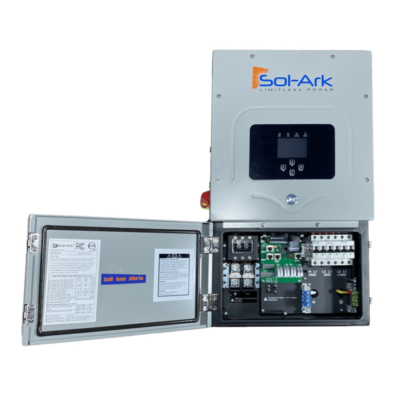
Page 3: Component Guide
WIFI Plug: For software updates and remote monitoring (use screws to hold in!) d. Limiter Sensors: for “Limited-to-Home Mode” (larger ones are optional) e. French Cleat: For wall mounting the Sol-Ark 12K f. Battery Temperature Sensor: For voltage adjustment g. - Page 4 If using multiple 12K units in parallel consider powering the main breaker panel directly as shown on page 15. (Example: 3 systems will have a total of 150A of pass through)
- Page 5 Sol-Ark User Area Important notes: When the transfer switch is in the “Gen” position, this means the circuit is being powered by the Sol-Ark (which can use Grid/Solar/Battery/Generator automatically). When in the “Line” position, the transfer switch is being powered by the grid (Sol-Ark can be removed).
-
Page 6: Mounting
Then use 2-3 screws (appropriate in length and type for your mounting surface) to mount the French Cleat to the board/wall (washers recommended). e. Mount the Sol-Ark on the installed cleat making sure that it sits properly and is level. f. Add 2 screws in bottom mounts. -
Page 7: Battery Wiring
9. Connect Batteries (Sol-Ark should be POWERED “OFF”) a. Connect the batteries to the Sol-Ark 12K as shown in the diagrams Fig. B below: Fig. A b. Fig. A: Install included ferrites (part k. on pg. 3) on the battery input cables. Slide the ferrite over the battery cables so that both cables are within the toroid (as shown in Fig. - Page 8 February 3, 2020...
-
Page 9: Solar Panel Wiring
1 ground wire is needed. Note: When connecting more than 13,000W +/- 10% of PV to Sol-Ark 12K, it is recommended that a portion of the array faces a different direction (Example: 2 strings west, 4 strings south). This increases the max total energy produced per day. - Page 10 If using Y-Connectors: (Running two strings in parallel, totaling 20A (self-limiting) Note: separate wires can be used per string, and string minimum is 5 panels or 175V) February 3, 2020...
-
Page 11: System Wire Diagram
February 3, 2020... - Page 12 February 3, 2020...
- Page 13 February 3, 2020...
- Page 14 February 3, 2020...
-
Page 15: Multi -System Wire Diagram
February 3, 2020... - Page 16 February 3, 2020...
- Page 17 February 3, 2020...
-
Page 18: Backup Gas Generator Setup & Sensor Placement
If Off-Grid, you may connect the generator output directly to the “Grid” input on the Sol-Ark 12K. The Sol-Ark 12K will perceive the generator as if it were the grid. You will need to select the “GEN connected to Grid input” option in the Sell Control tab of the Grid Setup Menu. -
Page 19: Battery Settings And Wifi Setup
15. Programming Battery Settings a. Battery Capacity This allows Sol-Ark to know the size of the battery bank. The system is also self-learning as batteries age. ii. Main Menu → System Settings → Battery Setup → Batt → Batt Capacity b. - Page 20 ▪ Follow this instruction on the following pages iv. Note: Sol-Ark 12K is not compatible with wired ethernet connections for monitoring or updates, you must use the included WIFI dongle. Once Setup is complete, Dongle will have a solid green LED and a solid Red light...
- Page 21 WiFi Setup Instructions 1. Download the App: Android: iPhone: https://apps.apple.com/us/app/powerview-es/id1460941008 https://play.google.com/store/apps/ details?id=com.elinter.app.ups 2. Open App 3. Create an Account Attention Installers If you plan to add an install to your installer account for monitoring multiple installs, you must first make your installer account.
- Page 22 4. Sign in If you see this pop up, enable location settings on your device 5. Add a Plant Scan the QR code Select the “+” icon on the dongle Pick a “Plant Name”, input a capacity for your install (PV), and an income ratio (this is how much you save by producing solar power)
- Page 23 6. Connect your system to the internet Select “Find device” Select “Tools” Select the “me” icon Once you see this screen go to your devices WiFi setting and connect to the WiFi network that starts with: EAP-##### Password: “12345678” Select “Pls_select” Once connected return to the app February 3, 2020...
- Page 24 Select the local WiFi network that will be Once your network is providing the internet If successful, the selected, enter the connection to the dongle will have one password to that WiFi system. red and one green network here then light.
-
Page 25: Emp Suppressor Installation
• If your system was purchased with Lightning / EMP Hardening, the vast majority of protection is in the Sol-Ark. However, you also have EMP suppressors that get installed on the power cords of appliances that are connected to the transfer switch. Although not critical, it is recommended they be installed as close as possible to the appliance. -
Page 26: Rapid Shutdown Diagrams
Note: If parallel systems: the RSD Signals for all systems must be in parallel and pass through the same RSD button Note: Transmitter fits inside the user area of the Sol-Ark 12K but can cause interference (placing it outside of... -
Page 27: Specifications
Sol-Ark-12K-P Specifications Solar Output Power 12000W Max allowed PV DC Capacity 8,250W+8,250W = 16,500W 12000W Max PV power delivered to Battery & AC outputs Max DC voltage 500V@18A, 450V@20A MPPT voltage range 150-425V MPPT Starting voltage 175V Number of MPPT... - Page 28 • If you would like to use a wind turbine in conjunction with Sol-Ark 12K, the turbine must have a 48V charge controller with a dump load as to prevent overcharging of the batteries. Simply connect the charge controller on the turbine to the battery bank the Sol-Ark is using and the turbine will help charge your batteries.
-
Page 29: Powering On The System / Indicator Led S
• Grid Sell Back o This Mode allows Sol-Ark 12K to sell back any excess power produced by the solar panels to the grid. o If home has a backup generator, this mode requires Limiter Sensors. See “Backup Generator Setup”... -
Page 30: Sensors
17. o If off grid, connect the output of the Generator directly to the Grid input on the Sol-Ark 12K. It can then treat the generator as if it were the grid. - Page 31 Touch the gear icon → Touch the Basic Setup button → Select the Advanced tab (see Fig. G). 3) Select “Auto detect Home Limit Sensors” and press ok. 4) Wait for the Sol-Ark to finish its learning process (Sol-Ark will alternate sell back between legs and magnitude automatically determining the correct settings for the sensors).
-
Page 32: Screens (Gui Map Page 38)
Screens • Home Screen (Touchscreen) Hold 3s to Force Smart Load Settings Grid Graphical View Detailed Volts PV Graphical View View Solar Power Production Battery Power Grid Power Load Power Charge(negative)/Discharge(positive) Sell(negative)/Buy(positive) Consumption • Detailed Volts View o Top row = Total power for column o Middle Row = Line 1/PV1 voltage, Amps, and Watts (note: PV Voltage not to exceed 500) o Bottom Row = Line 2/PV2 voltage, Amps, and Watts (note: PV Voltage not to exceed 500) o Batt Temperature will show -20°C if temperature sensor is not connected. - Page 33 Power to keep the power drawn from the grid below the threshold. o Gen Peak Shaving ▪ Set the threshold at which the Sol-Ark will contribute to the generator to prevent large loads overloading the generator. o Parallel (when using multiple systems, see page 44) ▪...
- Page 34 ▪ TEMPCO: Temperature coefficient used in conjunction with the batt temp sensor to adjust optimal voltages for lead acid batteries ▪ Use Batt V charged: displays battery charge in terms of voltage ▪ Use Batt % charged: Battery voltage can be misleading for determining the % Charged.
- Page 35 To use the Gen input breaker as a micro inverter AC coupled input, check the “For Micro inverter Input” box (this feature will also work with “Grid-Tied” Inverters) ▪ Maximum combined input to Sol-Ark (AC+DC) • Best: 3kWAC + 12kWDC (9KW sell) •...
- Page 36 • When on grid the AC coupled inverter will always be on and the power it produces will be sold back to the grid. Limited To Home mode will not function with AC coupled PV arrays. • Grid Setup o Limiter ▪...
- Page 37 o FreqVolt (UL 1741SA must enabled in “Sell Control” tab) ▪ Puerto Rico Grid Compliance Settings: ▪ Kauai Grid Compliance Settings: ▪ HECO Grid Compliance Settings for O’ahu, Maui, Hawai’i: ▪ HECO Grid Compliance Settings for Lana’I and Moloka’i: o PowFac ▪...
- Page 38 Sol-Ark 12K Menus Brightness Beep Auto Dim AM/PM Time Sync Hour Year Minute Second Month Display Solar Arc Fault ON Time Gen Peak Shaving Advanced Grid Peak Shaving Auto Detect Home Limit Sensors Factory Reset Clear Arc Fault Parallel Factory Reset...
-
Page 39: Battery Charge /Discharge Reference
Battery Charging Information 4-Stage Charging The MPPT has a 4-stage battery charging algorithm for rapid, efficient, and safe battery charging. The figure below shows the stage sequence. MPPT Charging Algorithm Bulk Charge Stage In Bulk Charge stage, the battery is not at 100% state of charge and battery voltage has not yet charged to the Absorption voltage setpoint. -
Page 40: Troubleshooting Guide / Error Codes
Auto Gen-Start not working o Check to make sure your generator is compatible with Auto Start o Make sure that the Auto Gen Start wire is connected properly to the Sol-Ark 12K and the generator • Normal LED isn’t on o Sol-Ark 12K is not working properly (Call us) •... - Page 41 Generator setup is reading 0Hz o Select “General Standard” instead of UL1741. Then widen the voltage range to 53Hz-65Hz. • Color Touchscreen is Frozen o Press and hold the escape button [] for 7-10 seconds Sol-Ark 12K Error Codes Fault Instruction Common Cause/Remedy AuxPowerBoard_Failure Contact Sol-Ark.com...
-
Page 42: Common Battery Application Note
Common Battery Application Notes Sol-Ark PCC-230 Battery Batt Capacity: 230Ah x #Parallel_Batteries Time Watts GridCharge (1 parallel = 4 Batt in series, 2 = 8 Batt, 3 = 12 Batt, 4 =16 Batt) 1:00AM 1500*Par_Batts Max A Charge: 100A x #Parallel_Batteries... -
Page 43: Wire Gauge Guide
Wire Gauge Guide 15.875mm (5/8in) 23.813mm (15/16in) (Copper) PV input: 10AWG 4/0 AWG Max 2/0 AWG Max Grid input: 6-4AWG Limiter Limiter Sensor Gen input: 6-4AWG Sensor Large Small Load output: 6-4AWG Inputs Inputs All Sensors: 20-24AWG 100A: 50mA Battery input: 2/0-4/0AWG (3/8 Lugs) 200A: 0.1A 15.875mm (5/8in) -
Page 44: Parallel System Application Note / Compatibility Reference
Parallel System Application Note • Communication lines must be connected between parallel units as shown in the wire diagrams section o CAT 6 may be used for this purpose • Program all units to “Parallel” in the basic setup screen under the parallel tab o Set one system to “Master”... -
Page 45: Install Testing Checklist
For installer to complete after system is operational. Purpose is to protect installer, homeowner, and inverter. 1. Is the 12K installed in a location protected from water and has 6” clearance left and right for cooling (12” between parallel systems)? Y/N 2. - Page 46 9. Turn off PV input, running only on batteries for several minutes. Are appliances still powered? Y/N In Limited To Home Mode HM values will be close to zero. HM values should never be negative. If negative, the Limiter Sensors are not installed properly.
-
Page 47: Warranty
This Warranty applies to the original Sol-Ark Product purchaser and is transferable only if the Product remains installed in the original use location. Please call Sol-Ark to let us know if you are selling your home and give us name and contact of the new owner.
Need help?
Do you have a question about the 12K and is the answer not in the manual?
Questions and answers