Table of Contents
Advertisement
Advertisement
Table of Contents

Related Manuals for Broan BCDJ1


Summary of Contents for Broan BCDJ1
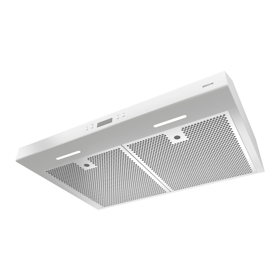
- Page 1 RANGE HOOD Series: BCDJ1 and NCDJ1 INSTALLATION, USE AND CARE MANUAL...
-
Page 2: Table Of Contents
Safety ....... . . 3-4 Operation ......5-6 Cleaning and Maintenance . -
Page 3: Safety
READ AND SAVE THESE INSTRUCTIONS Intended for domestic cooking only INSTALLER: LEAVE THIS MANUAL WITH HOMEOWNER. WARNING TO REDUCE THE RISK OF FIRE, ELECTRIC SHOCK, OR INJURY TO PERSONS, OBSERVE THE FOLLOWING: • Use this unit only in the manner intended by the manufacturer. If you have questions, contact the manufacturer at the address or telephone number listed in the warranty. - Page 4 WARNING TO REDUCE THE RISK OF A RANGE TOP GREASE FIRE: a) Never leave surface units unattended at high settings. Boilovers cause smoking and greasy spillovers that may ignite. Heat oils slowly on low or medium settings. b) Always turn hood ON when cooking at high heat or when flambeing food (i.e.: Crêpes Suzette, Cherries Jubilee, Peppercorn Beef Flambé).
-
Page 5: Operation
Operation Always turn your hood on before you begin cooking to establish an air flow in the kitchen. Let the blower run for a few minutes to clear the air after you turn off the range. This will help keep the whole kitchen cleaner and fresher. Operate the hood as follows: NOTE: At range hood start-up or after a power failure, a small icon (1) appears shortly (for ±... - Page 6 DELAY OFF When the blower is on, press this button to activate the delay function. This icon appears on LCD screen beside the blower icon to indicate the function is on. The blower will continue to operate for 10 minutes and then, will shut off automatically (both blower and delay icons will disappear from LCD screen).
-
Page 7: Cleaning And Maintenance
Cleaning and Maintenance Proper maintenance of the Range Hood will assure proper performance of the unit. MOTORS The motors are permanently lubricated and never need oiling. If the motor bearings make excessive or unusual noise, replace the motor with the exact service motor. The fan wheel should also be replaced. -
Page 8: Installation
Recommended Tools and Accessories for Installation • Measuring tape • Phillips screwdriver no. 2 • Nutdriver or socket 11/32” • Flat blade screwdriver (to open knockout holes) • Drill, 1/8” drill bit and 1½” hole saw (to mark holes for ducting and cut electrical access hole) •... -
Page 9: Contents
Contents Before proceeding to the installation, check the contents of the box. If items are missing or damaged, contact the manufacturer. Make sure that the following items are included: BCDJ1 Series: NCDJ1 Series: (1) 3¼” 10” (1) 7” R (1) 3¼”... -
Page 10: Prepare The Hood
1 ] If present, remove all protective polyfilm from the hood and/or parts. 2 ] For BCDJ1 Series only: Remove 7” Round Duct Plate from top/back of hood (see illustration below). Keep the screws for further use. For BCDJ Series and NCDJ1 Series: Remove the adapter/damper from back of hood (see illustration below). - Page 11 5 ] Remove the parts bag, taped on the inner back of hood, near the left corner. Remove the EZ1 brackets from inside the hood by cutting off the tie wrap. Discard the tie-wrap EZ1 BRACKETS PARTS BAG LOCATION 6 ] Remove Electrical Power Cable Knockout from top (vertical wiring) or back (horizontal wiring) of hood.
- Page 12 DUCTED INSTALLATION ONLY 8 ] Remove 3¼” x 10” vertical or 3¼” x 10” horizontal (both are the rectangular central knockout plates, see hatched areas) or 7-inch round knockout plate as appropriate for your ducting method (see F 1 A and 1 B). IGURES IGURE IGURE...
-
Page 13: Prepare The Hood Location
Prepare the Hood Location NOTE: Before starting installation, read all the steps of these instructions. Use the illustration below to identify your kitchen cabinet type. FRAMED CABINET FRAMELESS CABINET This manual covers 2 kinds of installation: the standard (without EZ1 brackets) and the EZ1 one-person installation system (using included template and brackets). - Page 14 4 ] Drill a 1/8” dia. pilot hole for house wiring, at B location on template. 5 ] Use a sharp pencil or 1/8” drill bit to mark the locations for the appropriate duct access holes (16 locations for 7” round duct, or 4 corner locations for rectangular duct). Remove the template.
- Page 15 FRAMELESS CABINET Refer to the marking on brackets to determine the correct installation side and orientation. 7/64” Align the corresponding bracket to the cabinet side, while placing rear end of bracket against the wall. Draw a line on the outer edge of the bracket (as shown). ...
-
Page 16: Install The Hood (Ez1 Bracket)
Install the Hood (EZ1 Bracket) OTE: The following procedure applies to both frame or frameless cabinet installations. 1 ] Run house power cable between service panel and hood location. 2 ] There are 2 pairs of recessed holes on each side of the top of the hood (on rear: A and B, on front C and D on illustration below);... - Page 17 7 ] For framed cabinet, secure the hood to the EZ1 brackets using four (4) no. 8-18 x 1/2” metal screws (included in parts bag). Insert two (2) screws per side, in the slots (as shown in insets on illustration below). 8 ] For frameless cabinet, secure the hood to the cabinet using four (4) no.
-
Page 18: Standard Installation
Standard Installation (without EZ1 brackets) 1 ] Use the proper diagram below for placement of ductwork and electrical cutout in cabinet or wall. For a non-ducted installation, DO NOT cut a duct access hole, only cut the hole for electrical wiring. 3¼"... -
Page 19: Install The Hood (Standard Installation)
Install the Hood (Standard Installation) OTE: Two installers are recommended because of the weight of this hood. 1 ] Run house power cable between service panel and hood location. For hood with power cable access located on back of hood, run the house power cable into the hood through the strain relief previously installed in step 6 on page 11. -
Page 20: Connect The Wiring
Connect the Wiring WARNING Risk of electric shock. Electrical wiring must be done by qualifi ed personnel in accordance with all applicable codes and standards. Before connecting wires, switch power off at service panel and lock service disconnecting means to prevent power from being switched on accidentally. -
Page 21: Wiring Diagram
BCDJ1 NCDJ1 SERIES ( SECOND GENERATION... -
Page 22: Service Parts
EPAIRS In order to ensure your unit remains in good working condition, you must use Broan-NuTone LLC or Venmar Ventilation ULC genuine replacement parts only. Broan-NuTone LLC or Venmar Ventilation ULC genuine replacement parts are specially designed for each unit and are manufactured to comply with all the applicable certification standards and maintain a high standard of safety. - Page 23 ARTS AND EPAIRS In order to ensure your unit remains in good working condition, you must use Broan-NuTone LLC or Venmar Ventilation ULC genuine replacement parts only. Broan-NuTone LLC or Venmar Ventilation ULC genuine replacement parts are specially designed for each unit and are manufactured to comply with all the applicable certification standards and maintain a high standard of safety.
- Page 24 EPAIRS In order to ensure your unit remains in good working condition, you must use Broan-NuTone LLC or Venmar Ventilation ULC genuine replacement parts only. Broan-NuTone LLC or Venmar Ventilation ULC genuine replacement parts are specially designed for each unit and are manufactured to comply with all the applicable certification standards and maintain a high standard of safety.
- Page 25 EPAIRS In order to ensure your unit remains in good working condition, you must use Broan-NuTone LLC or Venmar Ventilation ULC genuine replacement parts only. Broan-NuTone LLC or Venmar Ventilation ULC genuine replacement parts are specially designed for each unit and are manufactured to comply with all the applicable certification standards and maintain a high standard of safety.
Need help?
Do you have a question about the BCDJ1 and is the answer not in the manual?
Questions and answers