
Related Manuals for Woodward SPM-D Series


Summary of Contents for Woodward SPM-D Series
- Page 1 37616B SPM-D2-10B/PSY5 Synchronizing Unit Manual From Release 7.10-0 Manual 37616B...
- Page 2 Provides other helpful information that does not fall under the warning or caution categories. Woodward reserves the right to update any portion of this publication at any time. Information provided by Woodward is believed to be correct and reliable. However, Woodward assumes no responsibility unless otherwise expressly undertaken.
-
Page 3: Copyright And Disclaimer
The manufacturer cannot be held liable for any resulting damage, the user alone bears the risk for this. As to the appropriate use of the device: The technical data and tolerances specified by Woodward have to be met. -
Page 4: Table Of Contents
Control outputs........................23 6. D ..........24 HAPTER ISPLAY AND PERATING LEMENTS Brief explanation of the LEDs and push buttons ..............25 LEDs .......................... 25 Buttons ........................25 Others ........................25 LEDs ............................ 26 Push buttons ........................28 Page 4/58 © Woodward... - Page 5 Product Service Options ....................... 53 Returning Equipment For Repair..................53 Packing A Control ...................... 54 Return Authorization Number RAN ................54 Replacement Parts ....................... 54 How To Contact Woodward ....................55 Engineering Services ......................56 Technical Assistance ......................57 © Woodward Page 5/58...
- Page 6 Figure 4-11: Controller - SPM-D2-10B/PSY5-..D.. – three position controller ..........17 Figure 6-1: Front foil ............................24 Figure 8-1: Dimensions ............................48 Tables Table 5-1: Operating conditions .......................... 18 Table 5-2: Operating conditions - terms ......................19 Page 6/58 © Woodward...
-
Page 7: Chapter 2. General Information
On account of the large variety of parameter settings, it is not possible to cover every possible combination. The manual are therefore only a guide. In case of incorrect entries or a total loss of functions, the default settings can be taken from the enclosed list of parameters. © Woodward Page 7/58... -
Page 8: Chapter 3. Electrostatic Discharge Awareness
CAUTION To prevent damage to electronic components caused by improper handling, read and observe the pre- cautions in Woodward manual 82715, Guide for Handling and Protection of Electronic Controls, Print- ed Circuit Boards, and Modules. NOTE The unit is capable to withstand an electrostatic powder coating process with a voltage of up to 85 kV and a current of up to 40 µA. -
Page 9: Chapter 4. Installation
This must also bear a sign identifying it as an isolating switch for the unit. NOTE Inductivities connected (such as coils of operating current or undervoltage tripping units, or auxiliary or power contacts) must be connected to a suitable interference suppressor. © Woodward Page 9/58... -
Page 10: Wiring Diagram
Com m on(term . 3, 4, 5, 6) alternatively B a tte ry V oltagesystem1 Activationof param eter set B Enableisolatedoperation / blackstart 0V dc 24 V dc Referencepoint Subject to technical modifications. Figure 4-1: Wiring diagram SPM-D2-10B/PSY5-FU-D Page 10/58 © Woodward... -
Page 11: Spm-D2-10B/Psy5-Fu-D-W (Power Supply: 90
Readinessfor operation contact Com m on(term . 3, 4, 5, 6) B a tte ry alternatively V oltagesystem1 Activation of Parameter Set B Enableisolatedoperation / blackstart Referencepoint Subject to technical modifications. Figure 4-2: Wiring diagram SPM-D2-10B/PSY5-FU-D-W © Woodward Page 11/58... -
Page 12: Reference Point
Figure 4-5: Power supply (90..250 Vac / 120 to 375 Vdc, SPM-D2-10B/PSY5-FU-D-W) Terminal Description SPM-D2-10B/PSY5-..W - wide range power supply 90..250 Vac / 120 to 375 Vdc, max. 10 VA 2.5 mm² 2.5 mm² 0 Vac 2.5 mm² Page 12/58 © Woodward... -
Page 13: Measuring Inputs
Voltage system 2 - L2 2.5 mm² direct or Reference point: N-terminal of the low voltage Transformer system or star point of the voltage transducer ../100 V Sold.lug (measuring reference point); do not connect in three wire installations © Woodward Page 13/58... -
Page 14: System 1
Note: Connection corresponding to the mains configuration (see wiring diagram). Terminal Measurement Description Connection to the measuring circuit voltage corresponding to variant , or direct Voltage system 1 - L1 2.5 mm² or ../100 V Voltage system 1 - L2 2.5 mm² Page 14/58 © Woodward... -
Page 15: Discrete Inputs
(acc. DIN 40 719 part 3, 5.8.3) Make contact Enable CB 2.5 mm² Enable isolated operation / black start 2.5 mm² Activation of parameter set B 2.5 mm² Normally closed contact Reply: CB is open 2.5 mm² © Woodward Page 15/58... -
Page 16: Relay Outputs
250 V AC Relay output external device Figure 4-10: Relay outputs – control outputs II (messages) Root Switched Description Note: The relays close when the function is fulfilled. Message: Connect 2 2.5 mm² Readiness for operation 2.5 mm² Page 16/58 © Woodward... -
Page 17: Controller Outputs
Voltage controller Raise Common Figure 4-11: Controller - SPM-D2-10B/PSY5-..D.. – three position controller Terminal Description common 2.5 mm² higher Speed/frequency controller 2.5 mm² lower 2.5 mm² common 2.5 mm² higher Voltage controller 2.5 mm² lower 2.5 mm² © Woodward Page 17/58... -
Page 18: Chapter 5. Description Of Functions
No-load operation or synchronization or Slip or phase zero Synch-check or Synch-check Black start Black start Isolated operation 0: "OFF" / 1: "ON" / x: Signal of no significance (0 or 1) Table 5-1: Operating conditions Page 18/58 © Woodward... -
Page 19: Additional Conditions
- Voltage of system 2 > 50 % of rated voltage V - For voltage controller: Parameter "Voltage controller in no-load operation Isolated operation ON" - For frequency controller: Parameter "Frequency controller in isolated op- eration ON". Table 5-2: Operating conditions - terms © Woodward Page 19/58... -
Page 20: Control Inputs
Reference points connected with 0 V Bridge between terminal 7 and terminal 2 (0 V) Reference point of the discrete inputs potential-free: Terminal 2: 0 V (supply voltage) Terminal 7: 0 V or N (control voltage) Page 20/58 © Woodward... -
Page 21: Operating Conditions
The input "Enable CB" is set. The input "Reply CB is open" is set The connection is done without consideration of the inherent delay. In the phase-angle-zero-control mode the ana- log input should be selected for the frequency controller. © Woodward Page 21/58... -
Page 22: Synch Check
U1 is zero and U2 is zero (taking each configured zero voltage difference into account dU |U-0|). Moreover, in case a) and b) the frequency of U1 and U2 must be within the configured limits. Page 22/58 © Woodward... -
Page 23: Led "Closed" Flashes
The internal self-monitoring system stated an alarm. In this case a trouble-free function of the unit cannot be guaranteed and other appropriate measures have to be taken into account, if necessary. b) The synchronization time monitoring system is activated and has responded. © Woodward Page 23/58... -
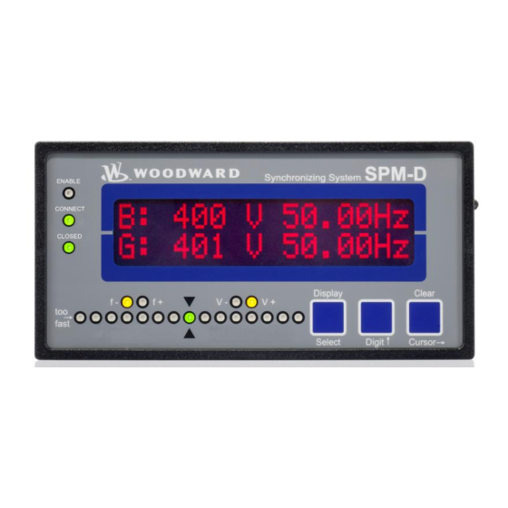
Page 24: Chapter 6. Display And Operating Elements
The display is a LC-display, consisting of 2 × 16 characters, which are indirectly illuminated red. Contrast of the display is infinitely variable by a rotary potentiometer at the left side. Figure 6-1: Front foil Page 24/58 © Woodward... -
Page 25: Brief Explanation Of The Leds And Push Buttons
Governor output: voltage raise (increase excitation) Buttons No Description Function Display Advance display Select Confirm selection Digit Increase digit Clear Acknowledge alarm Cursor Shift input position one digit to the right Others No Description Function LC-Display LC-Display Potentiometer Adjust LCD contrast © Woodward Page 25/58... -
Page 26: Leds
2 is too high, i. e., the system 2 turns too rapidly; right left .. If the LED's run from right to left, the frequency of sys- tem 2 is too low, i. e., the system 2 turns too slowly. Page 26/58 © Woodward... - Page 27 The LED "V+" indicates if the unit outputs a pulse to increase volt- age. The status of the LED corresponds to the status of the relay "voltage raise". Analog controller r If the actuating signal of the controller is changing to increase the voltage, the LED illuminates. © Woodward Page 27/58...
-
Page 28: Push Buttons
Configuration: Cursor - This push-button is used to move the cursor one position to the right. When the last right-hand posi- tion is reached, the cursor automatically moves to the first position left-hand of the value to be entered. Page 28/58 © Woodward... -
Page 29: Lc Display
2..Voltage and frequency of system 2 2:00,0kV 00,00Hz Display monitoring in automatic mode: Alarm indication Alarm indication, bottom line ---------------- xxxxxxxxxxxxxxxx The indications are displayed according to the following list: Type of alarm Displayed text Synchr. time Synchronization time is exceeded © Woodward Page 29/58... -
Page 30: Chapter 7. Configuration
Select "ToolKit" in the “application type” list. Click “Search” . Download the file displayed in the search result. The file is a ZIP archive which must be extracted for use in ToolKit. Page 30/58 © Woodward... -
Page 31: Configure Basic Data
SPRACHE/LANGUAGE english The screens (configuration and display screens) can be displayed in either German or English. Parameter 945 Softwareversion Softwareversion x.x-y zzzzz indicates the release. indicates the hotfix version. zzzzz indicates the build number (hand off) © Woodward Page 31/58... -
Page 32: Password Protection
ON ....Access to configuration is done by entering the relevant code number (code level 1/2). If a wrong code number was entered, the configuration will be blocked. OFF ....The user has direct access to all parameters, the code number is not requested. Page 32/58 © Woodward... - Page 33 Please note: This parameter will become visible only if parameter 10417 “Factory default settings” is set to “Yes”. Yes ....All parameters that are accessible via the set code level will be set back on factory defaults. No ....All parameters will keep their current setting. © Woodward Page 33/58...
-
Page 34: Configure Basic Settings
This value is used, among other things, to determine the permissible range for the synchronization. Parameter 8982 Setpoint voltage of system 2 50..440 V Voltage system 2 Setpoint 000V This value of the voltage specifies the setpoint of system 2 voltage for no- load and isolated operation. Page 34/58 © Woodward... -
Page 35: Configure Controller
(see also chapter "Function tables" on page 18) OFF ....No-load control is carried out only with controllers released (see also chapter "Function tables" on page 18). © Woodward Page 35/58... -
Page 36: Frequency Controller
The more rapidly the change in the setpoint is to be carried out, the greater the value input here must be. Page 36/58 © Woodward... - Page 37 B is active, if the discrete input at terminal 6 is set. 8988 on SPM-D2-10B/PSY5-..D.. ' The gain factor K influences the operating time of the relays. By increasing the factor, the operating time can be increased in the event of a certain con- trol deviation. © Woodward Page 37/58...
- Page 38 The more rapidly the change in the setpoint is to be carried out, the greater the value input here must be. Page 38/58 © Woodward...
- Page 39 The gain factor K influences the operating time of the relays. By increasing Volt. contr.(B) 9029 Gain Kp 00.0 the factor, the operating time can be increased in the event of a certain con- trol deviation. on SPM-D2-10B/PSY5-..D.. © Woodward Page 39/58...
- Page 40 To ensure that a connect command will be issued, the actual value must fall below the entered differential voltage. Parameter 3416 Min. pulse duration of connect relay 0.04..0.50 s Synchronization Brk.hold T>0.00s The duration of the connect impulse can be adjusted to the subordinate switching unit. Page 40/58 © Woodward...
- Page 41 The time counter will be reset, if one of the conditions, which are necessary for the switching, should not be met. © Woodward Page 41/58...
-
Page 42: Synchronization Time Monitoring
OFF ....The synchronization time will not be monitored. The subse- quent screens of this option are not displayed. Parameter 3063 Final value for synchronization time monitoring 10..999 s Sync.time contr. Delay time 000s Please refer to the above description of the configuration screen. Page 42/58 © Woodward... -
Page 43: Black Start
= 0.00Hz To make sure that the power circuit breaker will be closed, the deviation of the frequency of the voltage-carrying system from the rated frequency must not exceed the differential frequency pre-set . © Woodward Page 43/58... -
Page 44: Relay Output 16-17
Please note that this second contact assembly cannot be used as a substi- tute for a synch-check relay! Page 44/58 © Woodward... -
Page 45: Password Configuration
This screen first appears in code level 2 (password protection active). Fol- lowing the input of digits in this screen, the code level for level 2 (mechanic) is set. More information to password protection see on page 32. © Woodward Page 45/58... -
Page 46: Chapter 8. Commissioning
Check the status of all control and auxiliary inputs and the appropriate LEDs on the front foil of the unit. Check the status of all control and auxiliary outputs as well as the setting of the controller outputs. Page 46/58 © Woodward... - Page 47 Disconnect the connection to the power circuit breaker. b) Check all conditions and measuring voltages and test the add-on command. c) Automatically switching of the power circuit breaker. After successful closing of the power circuit breaker the LED "Closed" has to light up. © Woodward Page 47/58...
-
Page 48: Appendix A. Dimensions
Manual 37616B SPM-D2-10B/PSY5 - Synchronizing Unit Appendix A. Dimensions Configuration plug Configuration plug Front view Back plate mounting optionally Bottom view 108,8 Back view with connecting terminals PSY5-FU-A >> 2003-09-29 | SPM-D10B/PSY5 Dimensions 4003-ab.skf Figure 8-1: Dimensions Page 48/58 © Woodward... -
Page 49: Appendix B. List Of Parameters
0.10 Hz Freq. contr.(A) Time pulse> 10..250 ms 80 ms Freq. contr.(A) Gain Kp 0.1..99.9 Freq. contr.(B) Dead band 0.02..1.00 Hz 0.10 Hz Freq. contr.(B) Time pulse> 10..250 ms 80 ms Freq. contr.(B) Gain Kp 0.1..99.9 30.0 © Woodward Page 49/58... - Page 50 1..20 % Black start df max = 0.05..5.00 Hz 0.25 Hz Rel.connect 2 OFF / only asyn. / only syn. / syn/asyn. CONFIGURE PASSWORD Define level 1 code 0000..9999 0001 Define level 2 code 0000..9999 0002 Page 50/58 © Woodward...
-
Page 51: Appendix C. Technical Data
AC ..........2.00 Aac@250 Vac DC ..........2.00 Adc@24 Vdc 0.36 Adc@125 Vdc 0.18 Adc@250 Vdc Pilot duty (PD) (U Cont, relay output AC ..............B300 DC ..........1.00 Adc@24 Vdc 0.22 Adc@125 Vdc 0.10 Adc@250 Vdc © Woodward Page 51/58... - Page 52 Front foil .................. insulating surface EMV test (CE) ......tested according to applicable EN guidelines Listings ......... CE marking; UL listing for ordinary locations UL/cUL listed, Ordinary Locations, File No.: E231544 Communication Interface ------------------------------------------------------------------------ USB ....................Mini-Type B Page 52/58 © Woodward...
-
Page 53: Appendix D. Service Options
≡≡≡≡≡≡≡≡≡≡≡≡≡≡≡≡≡≡≡≡≡≡≡≡≡ If a control (or any part of an electronic control) is to be returned to Woodward for repair, please contact Wood- ward in advance to obtain a Return Authorization Number. When shipping the unit(s), attach a tag with the fol- lowing information: ... -
Page 54: Packing A Control
Stuttgart [+49 (0) 711 789 54-510]. They will help expedite the processing of your order through our distributors or local service facility. To expedite the repair process, contact Woodward in advance to obtain a Return Authori- zation Number, and arrange for issue of a purchase order for the unit(s) to be repaired. No work can be started un- til a purchase order is received. -
Page 55: How To Contact Woodward
For assistance outside Germany, call one of the following international Woodward facilities to obtain the address and phone number of the facility nearest your location where you will be able to get information and service. You can also contact the Woodward Customer Service Department or consult our worldwide directory on Wood- ward’s website (www.woodward.com) for the name of your nearest Woodward distributor or service facility. -
Page 56: Engineering Services
SPM-D2-10B/PSY5 - Synchronizing Unit Engineering Services ≡≡≡≡≡≡≡≡≡≡≡≡≡≡≡≡≡≡≡≡≡≡≡≡≡ Woodward Industrial Controls Engineering Services offers the following after-sales support for Woodward prod- ucts. For these services, you can contact us by telephone, by e-mail, or through the Woodward website. Technical support ... -
Page 57: Technical Assistance
Please be sure you have a list of all parameters available. You can print this using ToolKit. Additionally you can save the complete set of parameters (standard values) and send them to our Service department via e-mail. © Woodward Page 57/58... - Page 58 Phone +49 (0) 711 789 54-510 Fax +49 (0) 711 789 54-101 stgt-info@woodward.com Homepage http://www.woodward.com Woodward has company-owned plants, subsidiaries, and branches, as well as authorized distributors and other authorized service and sales facilities throughout the world. Complete address/phone/fax/e-mail information for all locations is available on our website (www.woodward.com).
Need help?
Do you have a question about the SPM-D Series and is the answer not in the manual?
Questions and answers