Advertisement
Table of Contents
- 1 Table of Contents
- 2 Important Safety Instructions
- 3 Items for Assembly
- 4 Console Use
- 5 Understanding Your Power10
- 6 Safety Warning Labels
- 7 & Product S Pec I F I Cat I O N S
- 8 Assembly Steps
- 9 Storage
- 10 User Adjustments
- 11 Rowing Direction
- 12 Muscle Targeting
- 13 Warranty and Registration
- Download this manual
A S S E M B LY & U S E I N S T R U C T I O N S
F A S T E R , B E T T E R
R E S U LT S W I T H
T E E T E R S U P P O R T
& C O A C H I N G
EN
Elliptical Rower
A S S E M B L E F A S T E R
Free BILT app puts easy 3-D
instructions at your fingertips.
Search 'Teeter Power10' in BILT
to get started.
R E A C H Y O U R G O A L S
Access on-demand,
trainer-led programs with
the free Teeter Move app
for fun, challenging and
effective workouts.
G E T S U P P O R T
Easily access support
through the Video Portal
to get the most from
your Power10.
N E E D H E L P ? C O N T A C T U S .
Phone:
Email:
Live Chat:
800-847-0143
info@teeter.com
teeter.com
Scan or
Find BILT
in App Store
Scan or
Find Teeter Move
in App Store
Scan or
Go to
teeter.com/videos
Advertisement
Table of Contents

Related Manuals for Teeter Power10


Summary of Contents for Teeter Power10
- Page 1 Free BILT app puts easy 3-D instructions at your fingertips. T E E T E R S U P P O R T Search ‘Teeter Power10’ in BILT Find BILT & C O A C H I N G to get started.
-
Page 2: Table Of Contents
Storage . . . . . . . . . . . . . . . . . . . . . . . . . . . . . . . . . . . . 17 Understanding Your Power10 . . . . . . . . . . . . . . . 3 User Adjustments . -
Page 3: Important Safety Instructions
BEFORE YOU BEGIN: Review all steps before beginning assembly and read all precautions before using the Teeter Power10 ™ Carefully adhere to the Assembly Instructions and User Guide to help ensure safety and product integrity . IMPORTANT SAFETY INSTRUCTIONS ™... -
Page 4: Console Use
I T EMS FO R ASSE M BLY Items not shown to scale . Hardware drawings located on the Hardware Kit insert . ITEM NO. ITEM NAME ITEM NO. ITEM NAME Base Assembly Handle Assembly XR1101 Base with Upper Left Handle XR1104L Lower Left Handle XR1102... -
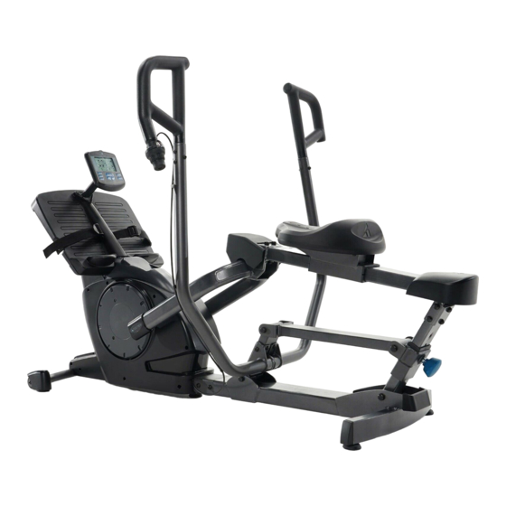
Page 5: Understanding Your Power10
UN DER STA N DIN G YO U R P OWE R10 Before reading further, study the drawing below to familiarize yourself with the important components of your Teeter Power10 . RIGHT BACK FRONT LEFT Identifying Parts and Components Console... -
Page 6: Safety Warning Labels
This drawing indicates the locations of the warning labels found on your product . If a label is missing, illegible or is removed, contact Teeter Customer Service to request a complimentary replacement label . Note: Image and labels below not shown at actual size . -
Page 7: Assembly Steps
L E T ’ S G ET STA RT E D Unpack and Prepare Your Workspace • If possible, assemble the equipment at or near the space in which you intend to use it to avoid moving it later . •... - Page 8 Step 2 Hardware Kit Figure 4: Use the Step 2 Hardware Kit to attach the Base Fork to the Rear Linkage Arm at the Fork Joint . Bolt (M10 x 60) Hand tighten 6 × Bolts with 6 × Washers on the Fork Joint .
- Page 9 F O O T P L AT F O R M A S S E M B LY FIGURE 4 IMPORTANT: Use caution to ensure the Cables on the Foot Platform and Foot Platform Joint do not get pinched or pulled while attaching the Platform Assembly .
- Page 10 IMPORTANT: Use caution to ensure the Cable does not get pinched or pulled while attaching the Foot Platform Joint Cover . Figure 10: Slide the top of Foot Platform Joint Cover so that it fits inside the front of the Foot Platform and then rotate the bottom of the Foot Platform Joint Cover into place so that it rests on top of the Base, enclosing the Foot Platform Joint .
- Page 11 Lift and Flip Figure 12: To have better access while proceeding to the next steps of assembly, position the Power10 to rest on its front side by lifting up on the Rear Handle and rotating on the Transport Wheels until the Foot Platform is resting on the ground .
- Page 12 L O W E R H A N D L E A S S E M B LY FIGURE 4 Figure 15a & 15b: While the Power10 remains tipped upward, align the Lower Left Handle with the Handle Support Bar on the Rear Linkage .
- Page 13 Figure 17a & 17b: Slide the base of the Lower Right Handle over the base of the Lower Left Handle until it aligns with the Handle Support Bar . Figure 17a Figure 17b Step 8 Hardware Kit Figure 18: Use the Step 8 Hardware Kit to attach the Lower Right Handle to the Handle Support Bar and Lower Left Handle .
- Page 14 S E AT A S S E M B LY FIGURE 4 Figure 19a & 19b: While the Power10 remains tipped upward, align the Seat with the Seat Support on the Rear Linkage . Figure 19a Figure 19b Step 9 Hardware Kit Figure 20: Use the Step 9 Hardware Kit to attach the Seat to the Seat Support .
- Page 15 U P P E R H A N D L E A S S E M B LY FIGURE 4 Figure 21: Return the Power10 to the in-use position by pulling down on the Rear Handle and rotating on the Transport Wheels until the Rear Linkage is resting on the ground .
- Page 16 Step 11 Hardware Kit Figure 24a & 24b: Use the Step 11 Hardware Kit to attach the Cable to the Lower Left Handle . First, open each of the 3 × Clips and insert the Cable into the rounded end of the Clips . Position each Clip over a hole in the Lower Left Handle and hand tighten 3 ×...
- Page 17 C O N S O L E A S S E M B LY FIGURE 4 IMPORTANT: The batteries can be installed and replaced without removing the console . However, for easier access, we recommend inserting the batteries before installing the console . Open the Battery Compartment located on the back of the console .
- Page 18 C O N S O L E U S E The Power10 Console is equipped with a Coded Polar Telemetric Heart Rate transmitter that allows you to monitor your heart rate while wearing a compatible chest strap . For optimal performance, we recommend the Polar T34 Polar Chest Strap that may be purchased at teeter .
-
Page 19: Storage
S T O R A G E Lift up on the Rear Handle to tip the Power10 onto the Transport Wheels to move to the storage location . Continue lifting up on the Rear Handle and rotating on the Transport Wheels until the Foot Platform is resting on the ground . -
Page 20: User Adjustments
U S E R A D J U S T M E N T S Seat Adjustment The seat offers twelve (12) settings to accommodate various heights . To ensure a safe and comfortable experience, adjust the seat to a setting that allows for a slight bend in your knees at full extension (Figure 30) . -
Page 21: Rowing Direction
R O W I N G D I R E C T I O N The bi-directional resistance with unique elliptical motion allows you to work both sides of your body, targeting specific muscle groups in one direction while you rest and recover others . This gives you the ultimate full body workout while allowing you to maintain high intensity without muscle burnout . -
Page 22: Muscle Targeting
Vary your upper body workout by changing your grip to target different muscle groups: Overhand Straight Wide Underhand Explore More on the Teeter Video Portal Access free video support, tips, and workouts online at teeter.com/videos or by scanning the QR code . -
Page 23: Warranty And Registration
. Under no circumstances shall Teeter, or any other party involved in the sale of this product, have any liability for incidental or consequential damage arising from breach of an express or implied warranty on any Teeter product . - Page 24 . c om | info@teeter . c om U .S . and Foreign Patents Apply . Teeter and Teeter logo are registered trademarks of Teeter . Specifications subject to change without notice . © COPYRIGHT 2020 Teeter . International Law Prohibits Any Copying . XR1040 0320-0...
Need help?
Do you have a question about the Power10 and is the answer not in the manual?
Questions and answers