Fluke BT521 User Manual
Battery analyzer
Hide thumbs
Also See for BT521:
- Quick reference manual (2 pages) ,
- User manual (66 pages) ,
- User manual (66 pages)

Related Manuals for Fluke BT521


Summary of Contents for Fluke BT521
- Page 1 BT521 Battery Analyzer Users Manual March 2014 © 2014 Fluke Corporation. All rights reserved. Specifications are subject to change without notice. All product names are trademarks of their respective companies.
- Page 2 Fluke authorized resellers shall extend this warranty on new and unused products to end-user customers only but have no authority to extend a greater or different warranty on behalf of Fluke. Warranty support is available only if product is purchased through a Fluke authorized sales outlet or Buyer has paid the applicable international price.
-
Page 3: Table Of Contents
Chapter Title Page Product Overview and Specifications ..........1-1 Introduction ....................1-1 Contact Fluke ................... 1-1 Product Overview ..................1-1 Standard Equipment ................1-3 Safety Information ..................1-4 Keys and I/O Terminals of the Product ........... 1-6 General Specifications ................1-8 Accuracy Specifications ................ - Page 4 BT521 Users Manual Load a Profile When Switched to Sequence Mode ......3-5 Make Measurements ................3-5 Test Battery Resistance and Voltage ..........3-5 Battery Test Probes ................. 3-6 View Test Readings on the Screen ..........3-6 Set Measurement Range ..............3-7 Save Battery Test Readings ............
- Page 5 Contents (continued) Install or Replace the Battery Pack ............7-3 Replace the Fuse ..................7-4 Clean the Product ..................7-5 Charge the Battery ................... 7-5 Parts and Accessories ................7-6...
- Page 6 BT521 Users Manual...
- Page 7 List of Tables Table Title Page 1-1. Standard Equipment ..................1-3 1-2. Symbols ....................... 1-5 1-3. Keys of the Product..................1-6 4-1. Elements of the Handle ................4-2 4-2. Typical Elements on the Handle Display ............. 4-3 7-1. Parts and Accessories ................. 7-6...
- Page 8 BT521 Users Manual...
- Page 9 List of Figures Figure Title Page 1-1. I/O Terminals of the Product ................ 1-7 2-1. Tilt Stand, USB Port and Battery Charger Input......... 2-1 3-1. Test Battery Resistance and Voltage ............3-5 3-2. Connect Test Lead to Battery Pole ............. 3-6 3-3.
- Page 10 BT521 Users Manual viii...
-
Page 11: Product Overview And Specifications
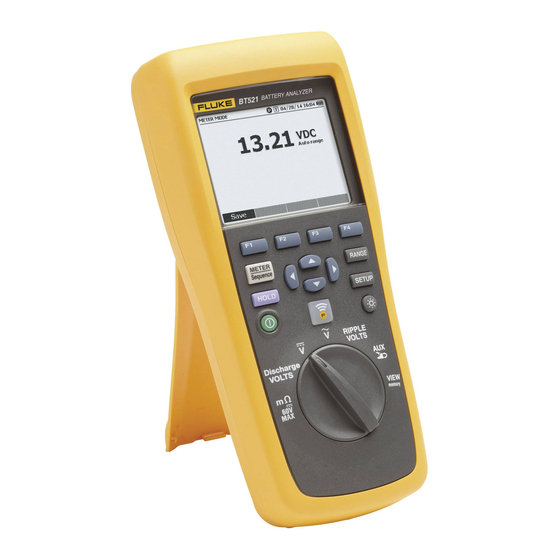
Product Overview The Fluke BT521 Battery Analyzer (the Product) is a multifunctional meter designed for the test and measurement of a stationary battery system. The Product can measure the battery internal resistance (hereinafter referred to as “resistance”) and voltages. These measurements can be used to determine the overall condition of the system. - Page 12 • Fluke Battery Analyze Software – Easily import data from the Product to a PC. The measurement data and battery profile information is stored and archived with the Analyze Software and can be used for comparison and trend analysis. All measurement data, battery profile and analysis information can be used to easily generate reports.
-
Page 13: Standard Equipment
Standard Equipment The items listed in Table 1-1 are included with the Product. Table 1-1. Standard Equipment Item No. Description Quantity Remarks BT521 Meter 7.4 V 3000mAh Lithium-ion BP500 (battery) battery 18 V dc power adapter BC500 (charger) Power cord... -
Page 14: Safety Information
BT521 Users Manual Safety Information A Warning identifies conditions and procedures that are dangerous to the user. A Caution identifies conditions and procedures that can cause damage to the Product or the equipment under test. Warning To prevent possible electrical shock, fire, or personal injury: •... - Page 15 Product Category: With reference to the equipment types in the WEEE Directive Annex I, this product is classed as category 9 "Monitoring and Control Instrumentation” product. Do not dispose of this product as unsorted municipal waste. Go to Fluke’s website for recycling information.
-
Page 16: Keys And I/O Terminals Of The Product
BT521 Users Manual Keys and I/O Terminals of the Product Table 1-3 identifies and describes the keys. Table 1-3. Keys of the Product hsz001.eps Item Function Softkeys that work flexibly for various functions on the display. Selects an item in a menu and scrolls through information. - Page 17 Product Overview and Specifications Keys and I/O Terminals of the Product Figure 1-1 shows the terminals of the Product. hpo002.eps Figure 1-1. I/O Terminals of the Product...
-
Page 18: General Specifications
BT521 Users Manual General Specifications Fuse Protection for Resistance ...... 0.44 A (44/100 A, 440 mA), 1000 V FAST Fuse, Fluke specified part only Power Supply Battery power ............BP500 smart battery pack: double cell lithium-ion, 7.4 V, 3000 mAh Battery life ............ -
Page 19: Accuracy Specifications
1 mV 3 % + 10 Amps dc/Amps ac (With 400 A 3.5 % + 2 accessory Fluke i410) Temperature 0 °C to 60 °C 1 °C ±2 °C The measurement is based on ac injection method. The injected source signal is <100 mA, 1 kHz. - Page 20 BT521 Users Manual 1-10...
-
Page 21: Basic Operation And Setup Of The Product
Chapter 2 Basic Operation and Setup of the Product Introduction This chapter describes the basic operation and setup of the Product. Tilt Stand The Product has a tilt stand that lets you see the screen at an angle when placed on a flat surface. -
Page 22: Adjust Display Contrast
BT521 Users Manual Adjust Display Contrast To adjust display contrast: 1. Push to open the Setup menu. Contrast is already highlighted. 2. Push the – softkey to lighten contrast, or push the + softkey to darken contrast. Note If – is pushed too far, the display is blank. -
Page 23: Turn On/Off Beep
Basic Operation and Setup of the Product Turn On/Off Beep Turn On/Off Beep To turn on or turn off beep: 1. Push to open the Setup menu. 2. Use L to highlight Beep, and push the Select softkey. 3. Use and L to highlight Off or On, and push the Confirm softkey. AutoHold and AutoSave Modes Note AutoHold and AutoSave are only available for the Battery... -
Page 24: Set Auto Power Off Time
BT521 Users Manual Set Auto Power Off Time The Product has an auto power off function to save power. It enables or disables auto power off. It also allows users to set the time between last operation and auto power off. -
Page 25: Use The Product
Use the Product Introduction Chapter 3 Use the Product Introduction This chapter provides information about how to use the Product. The Product provides two modes for different measurement purposes: Meter mode and Sequence mode. Meter mode lets you perform easy and fast measurements and save the measurement readings and timestamp to the Product memory. - Page 26 BT521 Users Manual hpo002.jpg hpo001.jpg To switch back to Meter mode: 1. Push M. 2. When the Back to METER mode? screen shows, push the Continue softkey. The measurement screen of Meter mode shows. Note All measurements taken in Sequence mode will be saved to the memory.
-
Page 27: Use A Profile In Sequence Mode
Manage Profiles Each Product stores up to 100 profiles. A profile describes the battery maintenance environment in a tree view. For example: • Site Name: Fluke • Device name: ABC 500kVA • Device ID: 1 • Battery series: 1 The PC software uses the same structure to categorize the profile. -
Page 28: Edit A Profile
BT521 Users Manual hpo012.jpg hpo004.jpg 3. Use and L to select Create by default or String+1. 4. Push the Create softkey. The New Profile menu shows on the screen. 5. When necessary, push the Edit softkey, and then use the arrow keys and softkeys to edit the field values. -
Page 29: Load A Profile
Use the Product Make Measurements The Profile info screen shows. 2. Push the Modify softkey. The Edit profile screen shows. 3. Use and L to highlight the data field to be edited. 4. Use the method in the “Edit a profile during creation” section to edit the profile. Load a Profile In Sequence mode, the Product can load a previously saved profile during measurement or when it is switched to Sequence mode. -
Page 30: Battery Test Probes
BT521 Users Manual Battery Test Probes To connect test probes to the battery pole: 1. Use the inner tip of the test probe to touch the target surface. 2. Push the test lead to set-back the inner tip, until both the inner tip and the outer tip are fully connected to the target surface. -
Page 31: Set Measurement Range
Use the Product Make Measurements This is a typical display of battery test in Sequence mode: hpo031.jpg Battery number: The number to the left of / indicates the number of the battery that is being tested. The number to the right of / indicates the total number of batteries in the profile. -
Page 32: Save Battery Test Readings
BT521 Users Manual Note The battery voltage measurement is in auto ranging mode, and the range cannot be changed. Caution In this function, the voltage between the positive and negative poles of a battery must be < 60 V. A voltage >60 V exceeds the rating of the fuse in the Product and causes an open circuit. -
Page 33: Set Measurement Thresholds
Use the Product Make Measurements Set Measurement Thresholds The Product can define upper and lower measurement thresholds or tolerance ranges. These defined threshold values are then compared to the measured values to automatically identify and prompt the user with a PASS, FAIL or WARN indicator of battery out of tolerance conditions. -
Page 34: How The Thresholds Work
BT521 Users Manual To disable measurement thresholds: 1. On the measurement screen, push the Threshold softkey to open the Select Threshold menu. The value of No. is already highlighted. 2. Use to set No. to ---. 3. Push the Confirm softkey. -
Page 35: Measure Dc Voltage
Use the Product Make Measurements Measure DC Voltage The Product can measure dc voltage. It also shows the polarity on the display. To measure dc voltage, turn the rotary switch to . See Figure 3-3 for connections. The link ed image cannot be display ed. The file may hav e been mov ed, renamed, or deleted. Verify that the link points to the correct file and location. hsz019.eps Figure 3-3. -
Page 36: Measure Ac Voltage
BT521 Users Manual Measure AC Voltage The Product supplies two independent readings to show the rms and frequency of ac voltage. To measure ac voltage, turn the rotary switch to . See Figure 3-4 for connections. hsz021.eps Figure 3-4. Measure AC Voltage Measurement Range The ac voltage measurement has only one range: 600 V. -
Page 37: Measure Ripple Voltage
Use the Product Make Measurements Measure Ripple Voltage The Product can measure the ac component on a dc voltage, which is also known as ac ripple. A high ac ripple may result in a battery overheat and negatively impact the battery life. -
Page 38: Typical Display
BT521 Users Manual Typical Display This is a typical display of discharge voltage measurement. hpo052.jpg Battery number: The number to the left of / indicates the number of the battery that is being tested. The number to the right of / indicates the total number of batteries in the profile. -
Page 39: Use The Handle And Probes
Chapter 4 Use the Handle and Probes Introduction This Product is shipped with an interactive handle. This chapter provides the information about how to use the interactive handle and the test probes. BTL21 Overview Warning To prevent possible electrical shock, fire, or personal injury, hold the handle behind the tactile barrier (). -
Page 40: Connect The Probe To The Product
BT521 Users Manual Table 4-1. Elements of the Handle Item No. Name Function Shows information such as measurement Display readings. Indicates the status of a measurement. Green means Pass; orange means Warning; red means Fail. Save button Manually saves a measurement reading. -
Page 41: Turn On/Off The Handle Power (Btl20/Btl21)
Turn On/Off the Handle Power (BTL20/BTL21) Turn On/Off the Handle Power (BTL20/BTL21) The interactive handle is powered by the Product. The handle powers on when it is connected to the Product. Push the power key below the display to turn on or turn off the handle power. When the handle is connected to the Product, the handle automatically turns on. -
Page 42: Interchange Long And Short Probes
BT521 Users Manual Interchange Long and Short Probes Figure 4-2 shows how to interchange the long and short probes. hsz024.eps Figure 4-2. Interchange the Long and Short Probes Note To get accurate readings, the connectors between the handle and probes should be fully fastened. -
Page 43: Replace The Probe Tips
Replace the Probe Tips Replace the Probe Tips Figure 4-3 shows how to replace the probe tips. Warning To prevent possible electrical shock, fire, or personal injury, use correct tip covers (CAT II or CAT III) in different CAT environments. -
Page 44: Zero Calibration
BT521 Users Manual Zero Calibration Each time before a probe is replaced, a zero calibration is required. To do zero calibration: 1. Locate the zero calibration board on a flat surface horizontally. 2. Insert the red and black probe tips to the calibration holes. -
Page 45: View Memory
Chapter 5 View Memory Introduction This chapter provides information about how to view measurement data that is manually or automatically saved to the Product memory. The Product has an internal memory that stores measurement data that can be viewed. Measurement data in Meter mode and Sequence mode shows separately. View Data Saved in Meter Mode To view measurement data that is saved in Meter mode: 1. -
Page 46: View Profiles Saved In Sequence Mode
BT521 Users Manual View Profiles Saved in Sequence Mode To view measurement data that is saved in Sequence mode: 1. Turn the rotary switch to VIEW memory. 2. Push M until MEMORY – SEQUENCE MODE shows on the upper left corner of the display. -
Page 47: Connection To Pc Or Mobile Device
Chapter 6 Connection to PC or Mobile Device Introduction This chapter contains information about how to connect the Product to a PC or mobile device. Connect the Product to PC The Product has a USB port that lets you connect the Product to a PC through a USB cable. - Page 48 BT521 Users Manual...
-
Page 49: Maintenance
Do not use any charger other than that specifically provided for use with the Product. • Do not use any battery which is not designed or recommended by Fluke for use with the Product. • Remove all probes, test leads, and accessories before the battery door is opened. - Page 50 • Connect the battery charger to the mains power outlet before the Product. • Use only Fluke approved power adapters to charge the battery. • Keep cells and battery packs clean and dry. Clean dirty connectors with a dry, clean cloth.
-
Page 51: Install Or Replace The Battery Pack
Maintenance Install or Replace the Battery Pack Install or Replace the Battery Pack Warning Never operate the Product with the Battery Cover removed. Hazardous voltage exposure may occur. To install or replace a Battery Pack: 1. Make sure the Product is off. 2. -
Page 52: Replace The Fuse
BT521 Users Manual Replace the Fuse Warning To prevent possible electrical shock, fire, or personal injury: • Use only specified replacement fuses. • Replace a blown fuse with exact replacement only for continued protection against arc flash. To replace the fuse: 1. -
Page 53: Clean The Product
Maintenance Clean the Product Clean the Product Warning For safe operation and maintenance of the Product, disconnect the Product and its accessories from all voltage sources during cleaning. Clean the Product with a damp cloth and a mild soap. Do not use abrasives, solvents, or alcohol. -
Page 54: Parts And Accessories
BT521 Users Manual Parts and Accessories Table 7-1 lists the user-replaceable parts and accessories. To order replacement parts or additional accessories, contact your nearest Fluke Service Center. See the “Contact Fluke” section. Table 7-1. Parts and Accessories Item Quantity Fluke Part Number...
Need help?
Do you have a question about the BT521 and is the answer not in the manual?
Questions and answers