Table of Contents
Advertisement
Quick Links
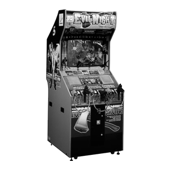
HELL NIGHT
●
Failure to operate the machine correctly could result in malfunction or accidents,so please
read this manual carefully before commencing operation. Be sure to operate the machine as
described in this manual.
●
Keep this manual carefully so as to be ready for use when necessary.
PN.0000055533 GQ810-TB
EVIL NIGHT
TM
TM
Advertisement
Table of Contents

Related Manuals for Konami HELLNIGHT


Summary of Contents for Konami HELLNIGHT
- Page 1 HELL NIGHT EVIL NIGHT ● Failure to operate the machine correctly could result in malfunction or accidents,so please read this manual carefully before commencing operation. Be sure to operate the machine as described in this manual. ● Keep this manual carefully so as to be ready for use when necessary. PN.0000055533 GQ810-TB...
- Page 2 About this product Thank you for purchasing this KONAMI product. This manual explains how to operate your game machine correctly and safely. •Failure to operate the machine correctly could result in malfunction or accidents, so please read this manual carefully before commencing operation.
-
Page 3: Table Of Contents
Contents Precautions for use ………………………………………………………… 2 Locations of warning and other safety labels ………………………… 7 Specifications ……………………………………………………………… 9 Names of parts ……………………………………………………………… 10 How to play ………………………………………………………………… 11 Opening and closing the doors 4-1 Opening and closing the maintenance door …………………………… 12 4-2 Opening and closing the coin door ………………………………………... -
Page 4: Precautions For Use
Precautions for use In this manual, the precautions to be followed without fail in order to prevent damage to persons to install, use or maintain “HELLNIGHT (EVILNIGHT )” or other persons or to properties are shown as follows. Be sure to read the following •The following suggestions show the degree of danger and damage caused when the... - Page 5 Precautions for use Setting Up WARNING •Be sure to consult your nearest dealer when setting up, moving or transporting this product. ·This product should not be set up, moved or transported by anyone other than industry specialist. Doing so could result in injury or product damage. ·When installing the machine, make sure that all the 4 adjusters are tight on the floor and that the machine is placed stably and horizontally.
- Page 6 Precautions for use Setting Up CAUTION •Be sure to use indoor wiring for within the specified voltage range. For extension cord, use indoor wiring of the specified rating or more. ·Failure to do so could result in fire or equipment failure. •Be sure to use the attached power cord.
- Page 7 Precautions for use Operation CAUTION •Do not use this product anywhere other than industrial areas. ·Using in a residential area or an area next to a residential area could affect signal reception of radios, television sets, telephones, etc.. •The following users should not play the game. ·Doing so could cause accidents or illness.
- Page 8 Precautions for use Moving and transportation CAUTION • The game machine contains parts such as the monitor, electronic components and precision components which are sensitive to vibrations and impacts. Great care therefore should be taken when moving and transporting the game machine. Be sure not to let the machine tip over.
-
Page 9: Locations Of Warning And Other Safety Labels
Locations of warning and other safety labels Types of warning and other safety labels • The above is an example. The entries are different from destination to destination. • GQ810-UC only... - Page 10 MEMO...
-
Page 11: Specifications
1 Specifications 920(36.2) 790(31.1) Specifications Dimensions Refer to the figure above : mm (in) Total weight Approx. 165 kg (363.8lb) Rated power consumption GQ810-TB : 180W / 230VA /actual power GQ810-SD / UC : 150W / 210VA Monitor 29-inch color monitor Service condition Temperature 5 to 40˚C (41 to 104˚F), Humidity 20 to 70% (No dewing is allowed.) ·Instruction manual ……………………………………………... -
Page 12: Names Of Parts
2 Names of parts and list of main parts Fluorescent light Cover glass Monitor Speaker Maintenace door Demagnetizing button Test button Coin Start button Service button selector Sub-power Mointor Gun unit 1 switch adjustment Gun unit 2 Coin box Gun cable clamp Coin door Coin counter... -
Page 13: How To Play
The red lamp lights up, and the on-screen gauge builds up. Setting the enemies’ blast-out styles In the “HELLNIGHT (EVILNIGHT )” game, there are 4 blast-out styles of the enemies to choose from. (Refer to “GAME OPTIONS” on page 18.) ·BLUE .... -
Page 14: Opening And Closing The Doors
4 Opening and closing the doors 4-1 Opening and closing the maintenance door How to open the maintenance door •Take care not to apply any load or impact to the maintenance door when it is open. •After closing the maintenance door, be sure to check that the door is locked securely. -
Page 15: Opening And Closing The Coin Door
4 Opening and closing the doors 4-2 Opening and closing the coin door Opening and closing the coin door and removing the coin box •Take care not to apply any load or impact to the coin door when it is open. •Securely lock the door for protection against burglaries. -
Page 16: Pcb Settings
5 PCB settings 5-1 PCB start-up check (self test) When the power switch is turned ON after installation of machine, the performance of game Printed Circuit Boards (PCB) is checked automatically and the result is displayed on the screen. If the power is not turned ON, make sure that the main power switch and sub-power switch are both at the ON position. -
Page 17: Adjusting The Game Environment (Manual Test)
5 PCB settings 5-2 Adjusting the game environment (manual test) Manually check and change the settings for the screen displays and game contents and change them as reguired. Starting the manual test mode 1 Turn ON the power switch. 2 While the demonstration game is playing, press the test button on the service panel. -
Page 18: Mode Descriptions
5 PCB settings 5-3 Mode descriptions The original factory settings are displayed in green; the changed settings are displayed in red. ·Press the 1P start button to select a setting to be modified. Pull the 1P gun trigger to change the setting. ·After the setting has been changed, select “SAVE AND EXIT”... - Page 19 5 PCB settings SCREEN CHECK Adjusting the screen distortion Mode for checking the screen display. Adjust the focus, distortion and size of the image on the screen while watching the crosshatch pattern. Use the monitor adjustment PCB (See page 34) to make adjustments.
- Page 20 5 PCB settings GAME OPTIONS Setting the game options Mode for setting and checking the game options. Press the 1P start button to select an item. Pull the 1P or 2P gun trigger to modify the setting. To return to the main menu screen, select “SAVE AND EXIT” or “EXIT” and pull the trigger of the 1P gun.
- Page 21 5 PCB settings COIN OPTIONS Setting the coin options Mode for setting and checking the coin options. Press the 1P start button to select an item. Pull the 1P gun trigger to change the setting. To return to the main menu screen, select “SAVE AND EXIT” or “EXIT” and pull the trigger of the 1P gun.
- Page 22 5 PCB settings BOOKKEEPING Displaying the coin data Mode for displaying the total data on the number of coins put in the machine. If the time is preset in this mode, the total data on the number of coins put into the machine can be viewed by coin slot.
- Page 23 5 PCB settings VIEW BOOKKEEPING INFORMATION In this mode, the bookkeeping information is displayed. The number of coins for each of the items can be viewed by coin slot. •Total number of coins after the time being set. VIEW BOOKKEEPING INFORMATION •Number of coins of today.
- Page 24 5 PCB settings CALIBRATION Setting the gun’s target points Mode for setting and checking the shooting target positions. Readjust and check the shooting target positions. To return to the main menu screen, select “SAVE AND EXIT” or “EXIT” and pull the trigger of the 1P gun.
- Page 25 5 PCB settings FLASH BRIGHTNESS Adjusting the brightness of flashes. Mode for adjusting the flash brightness on the screen. Press the 1P start button to select an item. Pull the 1P or 2P gun trigger to modify the setting. To return to the main menu screen, select “SAVE AND EXIT” or “EXIT” and pull the trigger of the 1P gun.
-
Page 26: Setting Up The Game Machine
6 Setting up the game machine 6-1 Fastening the adjusters How to fasten the adjusters •Adjust the adjusters so that the casters do not touch the floor. Take care not to exceed the maximum adjusting height of the adjuster. •Lower the 4 adjusters onto the floor. Make sure that the machine is stable and in a horizontal position. -
Page 27: Power Unit
6 Setting up the game machine 6-3 Power unit Power unit The power unit is located on the back of the machine. •Be sure to use the attached AC power cord. •Be sure to ground to the machine. Never connect the grounding wire to gas pipe, water pipe or telephone ground terminal. -
Page 28: Moving The Game Machine
6 Setting up the game machine 6-4 Moving the game machine How to movement •Before moving the machine, be sure to turn OFF the main power switch and unplug the power cord. •Before moving the machine, be sure to fully screw up all the adjusters. Move the machine on the casters. -
Page 29: Moving The Coin Counter
6 Setting up the game machine 6-5 Moving the coin counter How to move the coin counter The coin counter was installed in the coin box when the machine left the factory, but it can be moved onto the service panel. •Before moving the coin counter, be sure to turn OFF the main power switch and unplug the power cord from the receptacle. -
Page 30: Maintenance
7 Maintenance 7-1 Replacing the coin selector How to replace the coin selector •Before replacing the coin selector, be sure to turn OFF the main power switch and unplug the power cord from the receptacle. •When replacing parts, be sure to use parts of the correct specifications. Never use parts other than the specified ones. -
Page 31: Replacing The Fluorescent Light
7 Maintenance 7-2 Replacing the fluorescent light How to replace the fluorescent light •Before replacing the fluorescent light, be sure to turn OFF the main power switch and unplug the power cord from the receptacle. •Open and close the fluorescent light cover gently. •The florescent light is hot just after the power switch is turned off. -
Page 32: Replacing The Start Button
7 Maintenance 7-3 Replacing the start button How to replace the start button •Before replacing the start button, be sure to turn OFF the main power switch and unplug the power cord from the receptacle. •When replacing parts, be sure to use parts of the correct specifications. Never use parts other than the specified ones. -
Page 33: Replacing The Gun Unit
7 Maintenance 7-4 Replacing the gun unit How to remove the gun unit •Before replacing the gun unit, be sure to turn OFF the main power switch and unplug the power cord from the receptacle. •After the gun unit has been repaired or replaced, reposition the target points referring to “CALIBRATION”... - Page 34 7 Maintenance How to set up the gun unit Pass the gun cable through the bracket. Apply and lightly tighten the flange nut. Connectors Reconnect the gun cable connectors. Bracket Flange nut Fix the bracket with the screws and Screws Bracket tighten up the flange nut.
-
Page 35: Resetting The Circuit Protector
7 Maintenance 7-5 Resetting the circuit protector How to reset the circuit protector If an overcurrent or short circuit occurs, the circuit protector will be automatically actuated to protect the electric circuits of the game machine. When resetting the circuit protector, turn OFF the main power switch, unplug the power cord from the receptacle, eliminate the cause, and then press the button of the circuit protector. -
Page 36: Adjusting The Monitor
7 Maintenance 7-6 Adjusting the monitor Monitor adjustment PCB The monitor has already been adjusted at the time of shipment, but it may be readjusted as desired. The monitor adjustment PCB is located inside the service panel. When adjusting the monitor, open the maintenance door. (See page 12) Contrast adjustment CONTRAST Used to changes the contrast. -
Page 37: Annex
8 Annex 8-1 Label locations and exploded view Label Code No. Name Quantity Note 0000053902 LABEL, KONAMI / L 0000053892 LABEL, SIDE A / L 0000053893 LABEL, SIDE A / R 0000053894 LABEL, SIDE B / L 0000053895 LABEL, SIDE B / R... - Page 38 8 Annex FIG.1 UNIT, CABINET(1/7)
- Page 39 8 Annex FIG.2 UNIT, CABINET(2/7)
- Page 40 8 Annex FIG.3 UNIT, CABINET(3/7)
- Page 41 8 Annex FIG.4 UNIT, CABINET(4/7)
- Page 42 8 Annex FIG.5 UNIT, CABINET(5/7)
- Page 43 8 Annex FIG.6 UNIT, CABINET(6/7)
- Page 44 8 Annex FIG.7 UNIT, CABINET(7/7)
- Page 45 8 Annex FIG.8 UNIT, SHOT GUN...
- Page 46 8 Annex FIG.9 UNIT, HAND GUN...
- Page 47 8 Annex FIG.10 ASS’Y POWER BOX...
- Page 48 8 Annex FIG.11 UNIT, TRANSFORMER...
- Page 49 8 Annex FIG.12 UNIT, ATTACHMENT...
- Page 50 MEMO...
-
Page 51: Wiring Diagram
8 Annex GQ810-TB specifications for regions using 110 voltage area in Asia. 8-2 Wiring diagram... - Page 52 8 Annex GQ810-SD specifications for regions using 220 voltage area in Asia. Wiring diagram...
- Page 53 8 Annex GQ810-UC specifications for regions using 120 voltage area in the U.S.A.. Wiring diagram...
Need help?
Do you have a question about the HELLNIGHT and is the answer not in the manual?
Questions and answers