Federal Signal Corporation PA300 Series Installation And Instruction Manual
Electronic siren
Hide thumbs
Also See for PA300 Series:
- Installation and operating instructions manual (17 pages) ,
- Supplement sheet (3 pages) ,
- Installation, service, and operating instructions (20 pages)

Related Manuals for Federal Signal Corporation PA300 Series


Summary of Contents for Federal Signal Corporation PA300 Series
- Page 1 Model PA300 Series Electronic Siren Models 690000, 690001, 690002, 690004 Installation and Instruction Manual 2561788A Rev. A3 0520 © Copyright 2004 - 2020 Federal Signal Corporation...
- Page 2 A copy of this limited warranty can also be obtained by written request to Federal Signal Corporation, 2645 Federal Signal Drive, University Park, IL 60484, email to info@fedsig.com or call +1 708-534-3400.
-
Page 3: Table Of Contents
Contents Safety Messages for Installers and Operators ................4 Overview............................7 Unpacking ............................8 Installation ............................9 Testing the Installation ........................15 Operating the Unit ......................... 15 Getting Technical Support and Service ..................17 Tables Table 1 Specifications ........................8 Table 2 Parameters ........................ -
Page 4: Safety Messages For Installers And Operators
If drilling must be done near the unit, place an ESD approved cover over the unit to prevent metal shavings from entering the unit. Inspect the unit after mounting to be sure there are no shavings present in or near the unit. Model PA300 Series Electronic Siren Federal Signal www.fedsig.com... - Page 5 Safety Messages for Installers and Operators • Do NOT connect this system to the vehicle battery until ALL other electrical connections are made, mounting of all components is complete, and you have verified that no shorts exist. If wiring is shorted to vehicle frame, high current conductors can cause hazardous sparks, resulting in electrical fires or flying molten metal.
- Page 6 • At the start of your shift, ensure that the entire warning light system and the siren system are securely attached and operating properly. • Failure to follow these precautions may result in property damage, serious injury, or death. RETAIN AND REFER TO THESE MESSAGES Model PA300 Series Electronic Siren Federal Signal www.fedsig.com...
-
Page 7: Overview
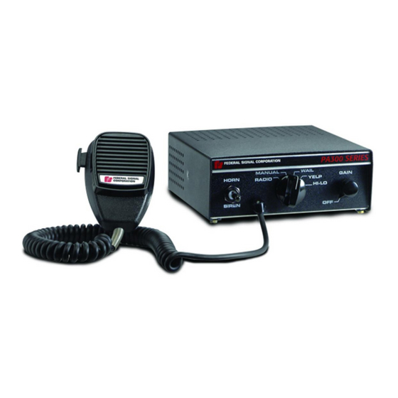
To use the PA functions, order the optional Model MNCT-SC microphone. The Model PA300 Series can drive one 11-ohm impedance, high power (100 W) or low power (58 W) speaker. The Tap II feature enables the driver to change the siren sound from wail to yelp (or vice versa) via the vehicle’s horn ring. -
Page 8: Unpacking
(Radio) Unpacking After unpacking the Model PA300 Series, examine it for damage that may have occurred in transit. If it has been damaged, do not attempt to install or operate it. File a claim immediately with the carrier, stating the extent of damage. Carefully check all envelopes, shipping labels, and tags before removing or destroying them. -
Page 9: Installation
Installation Installation PROPER FUSING: To avoid damage to unit, ensure that it is properly fused, with an 20 A in-line fuse and fuseholder installed in the red power cable lead. Mounting Bracket AIRBAG DEPLOYMENT: Do not install equipment or route wiring in the deployment path of an airbag. -
Page 10: Figure 2 Rear View Of Pa300
WILL be damaged if two speakers are installed. Speaker The unit is designed to operate with one 11-ohm impedance speaker or one low power (58 W) speaker. See Figure 2. Figure 2 Rear View of PA300 Model PA300 Series Electronic Siren 290A4452-03 Federal Signal www.fedsig.com... -
Page 11: Figure 3 Control Cable Wiring Diagram
Installation Damage to the unit will occur if speaker wires are improperly connected. NEVER CONNECT the brown SPEAKER HIGH POWER (100 W) wire and orange SPEAKER LOW POWER (58 W) wire together to the speaker(s). Using 18 AWG wire, connect one speaker lead (58 W speaker to SPEAKER LOW POWER or 100 W speaker to SPEAKER HIGH POWER) as shown in the Control Cable Wiring Diagram, Figure 3. - Page 12 PROPER FUSING: To avoid damage to unit, ensure that it is properly fused, with an 20 A in-line fuse and fuseholder installed in the red power cable lead. The PA300 Series can operate only from a 12-volt negative ground vehicle electrical system. Therefore, before making any electrical connections, determine the polarity of the vehicle electrical system ground.
-
Page 13: Figure 5 Press-And-Hold Modification - Factory Configuration
Installation If your vehicle has a negative ground electrical system, perform the procedure as follows: NOTE: This unit is NOT designed to operate with positive ground. 1. Route the red power (+) and the black power (-) control cable leads through the previously drilled hole and into the engine compartment. -
Page 14: Figure 6 Press-And-Hold Modification - Air Horn Configuration
R39 from the back of the siren to the desired sound level. See Figure 7. Figure 7 Relative PA Loudness 290A4452-08 After the adjustment is completed, the loudness of the radio rebroadcast and public address may be varied with the front panel GAIN control. Model PA300 Series Electronic Siren Federal Signal www.fedsig.com... -
Page 15: Testing The Installation
Testing the Installation Testing the Installation All effective sirens and horns produce loud sounds (120 dB) that may cause permanent hearing loss. Always minimize your exposure to siren sound and wear hearing protection. Do not sound the siren indoors or in enclosed areas where you and others will be exposed to the sound. -
Page 16: Table 4 Tap Ii Functions
Table 4 TAP II Functions Selector First Horn Second Horn Switch Ring Tap Ring Tap Position Produces Produces Wail Yelp Wail Yelp Wail Yelp Model PA300 Series Electronic Siren Federal Signal www.fedsig.com... -
Page 17: Getting Technical Support And Service
Air Horn Silence or Silence Getting Technical Support and Service For technical support and service, please contact: Service Department Federal Signal Corporation Phone: 1-800-433-9132 Email: empserviceinfo@fedsig.com www.fedsig.com Getting Repair Service The Federal Signal factory provides technical assistance with any problems that cannot be handled locally. -
Page 18: Table 7 Replacement Parts
Switch, Gain Control 106128 Harness, Wiring 1461360 Kit, Installation Accessory 8537561 Bracket, Mounting 8536B022 Faceplate, Logo PA300 81461864 Faceplate, PA300 (690000 and 690001) 81461865 Faceplate, PA300 (690002 and 690004) 81461865-01 Adapter Cable 761300 Model PA300 Series Electronic Siren Federal Signal www.fedsig.com... -
Page 19: Figure 9 Internal View
Figure 9 Internal View Output Transistor Output Transistor Output Transformer Microphone Gain Control Faceplate Logo Gain Control Faceplate Selector Knob Toggle Switch Rotary Switch Knob 290a4452-10... - Page 20 2645 Federal Signal Drive University Park, Illinois 60484-3167 www.fedsig.com Customer Support Police/Fire-EMS: 800-264-3578 • +1 708 534-3400 Work Truck: 800-824-0254 • +1 708 534-3400 Technical Support 800-433-9132 • +1 708 534-3400...
Need help?
Do you have a question about the PA300 Series and is the answer not in the manual?
Questions and answers