
Subscribe to Our Youtube Channel
Related Manuals for MTS Systems OrthoGold100 OW100-US


Summary of Contents for MTS Systems OrthoGold100 OW100-US
- Page 1 Instructions for Use ® OrthoGold100 Model: OW100-US (US-510K, K182682) Revision A, 2019-01-09 Caution: Federal law restricts this device to sale by or on the order of a physician. MTS_OW100_IFU-orthogold100-US-K182682_A...
-
Page 2: Table Of Contents
Table of Contents Glossary ............................5 Symbols Used in this Document ................................5 Symbols Used on the Product Labels ..............................6 Introduction ..........................9 Device Information ........................9 Indications for Use ..................................9 Contraindications ..................................9 Warnings ..................................... 10 Cautions ...................................... 10 Device Description .................................. - Page 3 Tables ® Table 1: List of delivered parts with the OW100 ..................21 Table 2 Recommended safety distances between Mobile HF Telecommunication Devices and the ® OW100 ..............................57 Table 3 Electromagnetic Interference ...................... 59 Table 4 Resistance to Electromagnetic Interference ................60 Table 5 Guidance and manufacturer´s declaration ..................
- Page 4 Figure 40 Example of an error message. The picture shows, that there are several error messages piled up ..............................66 Figure 41 Example of a warning message .................... 66 Figure 42 Example of Information Error ....................66 ® Figure 43 Transport box OW100 - Closed (left), opened with device (right) ........
-
Page 5: Glossary
Glossary Symbols Used in this Document This symbol indicates articles in which additional information and/or hints to the respective circumstances are given. Warning: read user manual Warning´: Ear protection Connection assignment for the footswitch Connection assignment for the memory card Connection assignment for the USB interface Connection assignment for the primary fuses MTS_OW100_IFU-orthogold100-US-K182682_A... -
Page 6: Symbols Used On The Product Labels
Symbols Used on the Product Labels Symbol Meaning Ref. ID* Refer to instruction M002 manual/booklet CAUTION 0434A Manufacturer 3082 Date of manufacture 2497 Temperature 0632 Humidity 2620 Atmospheric pressure limitation 2621 5840 Type B applied part Foot switch 5114 Applicator 4349 * ISO 7000: Graphical Symbols For Use On Equipment - Registered Symbols MTS_OW100_IFU-orthogold100-US-K182682_A... - Page 7 The following labels are attached to the device or the applicator: Type plate of the basic unit, exemplified: Type plate of the transport box, exemplified: Type plate of the footswitch, exemplified: MTS_OW100_IFU-orthogold100-US-K182682_A...
- Page 8 Type plate of the applicator, exemplified: Type plate of the cartridge, exemplified: Type plate of the applicator packaging, exemplified: MTS_OW100_IFU-orthogold100-US-K182682_A...
-
Page 9: Introduction
1. Introduction This manual instructs the user in the proper use and operation of the of the ® OrthoGold100 device. Please read these instructions carefully before starting treatment. The user must thoroughly understand the information presented in this manual and inform the patient of all risks associated with the treatment. -
Page 10: Warnings
Do not direct the acoustic waves on internal air-filled organs (especially lungs). All other Contraindications mentioned in scientific literature Do not use in areas where skin surface is broken or an open wound exist. Never use this device on children, the unconscious, or anyone who cannot give verbal consent or warnings about pain. -
Page 11: Device Description
Transient moderate increase in pain Redness and swelling Hematoma and petechial hemorrhage Headaches and fainting during extracorporeal acoustic wave treatments Short-term hypaesthesia Nausea during therapy Tingling during therapy 2.5 Device Description Overview ® ®... -
Page 12: Figure 2 Components And Connections Of The Ow100 At The Front Side
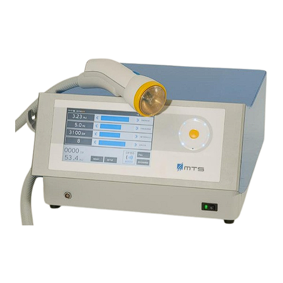
Front View ® The OW100 contains the water circuit, the high voltage parts, the electrohydraulic acoustic wave generator, the voltage supply and the microprocessor. The following parts are accessible from the outside: The applicator (1), in which the acoustic waves are generated and modulated. The applicator will be connected by means of the applicator connector to the ®... -
Page 13: Figure 3 Components And Connections Of The Ow100
Rear View The power supply socket (8) serves to connect the delivered power cable. The use of the memory card slots (9) is meant only for service purpose. The memory card stores the technical errors appearing during operation and the Log- files. -
Page 14: Figure 4 Applicator
Applicator The applicator is delivered as an accessory. The total number of acoustic waves available in the applicator are 100,000 acoustic waves at an energy level of 1-10. At an energy level of 11-16 the number of total acoustic waves 70 000. Once the applicator is depleted, it should be exchanged with a new one. -
Page 15: Figure 5 Water Cartridge Of The Ow100 At The Rear Side
The applicator serves the following tasks: Generation and emission of unfocused acoustic waves The applicator is filled with water to enable the generation and the transport of the acoustic waves. The special shape of the reflector (OP155) allows reflecting the acoustic waves in an unfocused pressure field outside the applicator. -
Page 16: Figure 6 Front Side Connections Of The Ow100
Water Applicator / membrane Image Outarcing Penetration Pressure depth (-6dB) at Level membrane energy level 16 [mm] [mm] adjustable by user 25,4 Probe Cover A general-purpose probe cover or sheath should be used for each patient or treatment area to avoid possible contamination of the membrane or cross contamination between patients or sites. -
Page 17: Figure 7 Connections At The Rear Side
Rear side connections At the rear side, you will find the following connections: Power connection socket (1) Memory card slot (2) USB-interface (3) Water cartridge (4) Figure 7 Connections at the rear side Power connection socket (Figure 7, #1): ®... -
Page 18: Figure 8 Applicator Connection Socket (Left) And Connect Applicator (Right)
Side connections At the left side of the device, the connection for the applicator is placed. Figure 8 Applicator connection socket (left) and connect applicator (right) Applicator (1) Applicator connection socket (2) Applicator connection plug (3) The plug and the flexible hose contain the power- and water supply for the applicator. The connection of the applicator happens automatically, which makes the connection simple and comfortable. -
Page 19: Figure 10 Touch Panel (Left) And Touch Wheel (Right) Of The Ow100
® Figure 10 Touch panel (left) and touch wheel (right) of the OW100 Footswitch (Figure 11) By activating the footswitch acoustic waves are released. The footswitch ® has to be connected to the connection socket at the front side of the OW100 Footswitch Use only the provided footswitch (Steute, Type RF 2S-MED-AP) ®... -
Page 20: Set-Up Instructions
3. Set-up Instructions Unpack OW100 Open the transport box and take out the device and accessories. Place the device on a firm surface. Ensure that the support is stable enough to hold the weight of the device. ® Weight of OW100 ®... -
Page 21: Table 1: List Of Delivered Parts With The Ow100
® : List of delivered parts with the OW100 Table 1 Name Description Quantity OrthoGold100 1000013 Model: OW100-US Applicators: 1000263 OP155 Footswitch (Steute, Type 1003094 RF 2S-MED- Power cable 1003080 (Example) Water cartridge 1003156 (limited lifetime as labelled) Instructions for Use 8124... -
Page 22: Figure 12 Installation Of Power Supply
Figure 12 Installation of power supply Electric Shock Hazard! Never remove the covers of the electronics cabinet. The high voltage power supply circuits utilized by extracorporeal shock WARNING wave devices use voltages that are capable of causing serious injury or death from electric shock. Danger of Electric Shock! Keep the device away from splashing water, especially the electronic parts. -
Page 23: Applicator
Electrical hazard danger Make sure that the designated wall socket has a PE connection! WARNING Standards of the local power supply Ensure that the power connector of the CAUTION ® OW100 fits to the existent power socket. 3.1 Applicator ® applicator should be exchanged after its use life (when display shows “0”). -
Page 24: Figure 13 Applicator Connection - Inside View (Left) And Socket (Right)
3. Press the plug against the socket until the implemented motor recognizes the plug and activates the pull in mechanism in the correct position. Figure 13 Applicator connection - inside view (left) and socket (right) Figure 14 Connected applicator ®... -
Page 25: Applicator Connection
Damaged Applicator Packing! Do not use the applicator if the packing is damaged! WARNING Usage of applicators At the standard configuration setting, up to five applicators of ® the same type can be used with an OW100 device. The NOTE device can store up to five applicators in its internal memory. -
Page 26: Changing And Disconnection Of Applicator
an analysis of the electrode adjustment after insertion of the applicator plug. After analysis, the number of remaining acoustic waves will be indicated in numeral values. That may take up to 15 seconds. There will be a blue message box with the information of “Applicator check in progress”. - Page 27 Disconnection of the applicator: Disconnect the water cartridge when the applicator is drained and NOTE disconnected for installing a new applicator or for storage. Drain the Applicator To change the applicator proceed as follows: ® 1. The OW100 must be switched on and the connected applicator must be filled. 2.
-
Page 28: Figure 16 Applicator Drain Control
Exchange of the applicator in optional modes: “FRD” & “FRD %” When ejecting an applicator with one of the two modes, “FRD“ or “FRD %” set, the following message will be displayed on the screen: The device performs at first a full reference drive and adjusts the electrode into position. -
Page 29: Water Cartridge
3.4 Water Cartridge Insert / change water cartridge After the water is consumed by acoustic wave releases or for initial operation, the water cartridge (Figure 20) should be exchanged / inserted. The device shows a message box when the water of the water cartridge is dissipated, and it is time to exchange for a new one. -
Page 30: Figure 20 Water Cartridge Of The Ow100 Shown From Above (Left) And From Front Side (Right)
Insertion of the water cartridge: 1. Push the water cartridge into the pit. Ensure that the 3 coupling plugs point toward the inside as shown by the arrow in Figure 20. 2. Press the cartridge tight inside until it locks. ®... -
Page 31: Connect The Footswitch
® Figure 21 Set-up Menu of the OW100 3.5 Connect the Footswitch ® Connect the footswitch (2) to the socket (1) at the front side of the OW100 Pressing the footswitch releases acoustic waves. 1. Connection of the footswitch 2. Footswitch Figure 22 Connected Footswitch MTS_OW100_IFU-orthogold100-US-K182682_A... -
Page 32: Menu Setup
3.6 Menu setup To get to the setup menu press “Setup”. Figure 23 "SETUP' Key field In the “Setup” menu, you can vary device internal and individual screen settings such as screen brightness, etc. MTS_OW100_IFU-orthogold100-US-K182682_A... -
Page 33: Operating Instructions
In the menu „Language“, select your national language for all displays (menus). Under „Brightness“ select the backlight illumination of the screen. Under „Energy“ select the exposition of the display: „1-16, „mJ“ or „mJ/mm “. Note: In this menu you can select only with the arrow buttons. - Page 34 Electromagnetic Interference The device emits electromagnetic radiation when acoustic waves are released. Devices sensitive to electromagnetic interference should not be operated close to the device (e.g. cardiac pacemakers, etc.). If electromagnetic interference between the extracorporeal acoustic wave device and nearby electronic equipment is WARNING suspected (as evidenced by erratic behavior with either device), it is recommended to increase the distance between the devices...
- Page 35 AM-, FM, TV- antennas ® Observe the essential requirements of the OW100 if the device is used closer than 1.5km (0.9 miles) from an AM-, FM- or a TV- antenna. ® If the OW100 1. Shows wrong energy parameters CAUTION 2.
- Page 36 ® The OW100 is intended for use by medical professionals only. ® The OW100 may cause radio interference or interfere with the operation of nearby equipment. WARNING It may become necessary to take appropriate actions, such as re- orientation or re-arranging the devices or the shielding. Floor surface! Floors should be wooden or concrete or be covered with ceramic tiles.
-
Page 37: Figure 24 Power Switch Activated
Figure 24 Power switch activated 3. Once the flashing button turns solid (1), press the confirmation button (2) for 2 seconds (Figure 25). Thereafter the device shows the start screen (Figure 26) and subsequently the operation screen (Figure 27). The device is now ready. Figure 25 Step 3 - when to press the confirmation button ®... -
Page 38: Figure 27 Operation Screen
Figure 27 Operation screen Malfunction Do not use the device if after switching on another nessage is displayed as shown in figure 26 & 27. Switch off the device and WARNING call service. Safe device against unintended use. Switching out of stand-by-mode If the device is in stand-by-mode (screen dark, power switch illuminated and the lower LED in touch-wheel illuminated), press confirmation button in the touch wheel for 2 ®... -
Page 39: Figure 28 "Fill" Key On The Display
The functional test is successful when the shot counter registers the number of waves released from the device and the user hears the audible release of the waves. The functional test has failed if the counter does not register released waves, there is no sound coming from the device during release of waves, or if the device displays an error message. - Page 40 4. Make sure that the patient is prepared for the treatment and the water membrane and applicator housing are cleaned and disinfected. Clean and disinfect with customary, inorganic and non-flammable disinfectants. 5. Place the device close to the patient and check, if there is enough space to move the applicator over the treatment area.
- Page 41 Step 3: Place the applicator in the cover bag containing the ultrasound gel. Make sure that membrane of the applicator has good contact with the ultrasound gel. Step 4: Pull the cover over the applicator head as shown. MTS_OW100_IFU-orthogold100-US-K182682_A...
- Page 42 Step 5: Ensure full contact between the cover-ultrasound gel-membrane (No air inclusion) Step 6: Fasten cover with provided rubber band or ligature to ensure secure positioning over the membrane. Step 7: Apply ultrasound gel on the area to treat and start the therapy. MTS_OW100_IFU-orthogold100-US-K182682_A...
-
Page 43: Setting The Output Parameters
Danger of infection The applicator must never get in direct contact with skin injuries or abscesses. Otherwise infectious material can contaminate the WARNING water membrane/ applicator or the water membrane can contaminate the wound. 4.1 Setting the Output Parameters Operation with the Touch Panel To adjust the treatment parameters, you can use the touch panel or the touch wheel. -
Page 44: Figure 29 Touch Panel Of The Ow100
® Figure 29 Touch panel of the OW100 Currently set values Key field “Arrow” to decrease a value Key field “Bar” to set a value and for a short overview in which area the set value is (min. - max.) Key field “Arrow”... -
Page 45: Figure 30 Touch Wheel Of The Ow100
Touch sensitive area Push button for confirmation ® Figure 30 Touch wheel of the OW100 Setting the energy level Press one of the arrow buttons under “ENERGY”, to increase the energy (> right arrow) or to decrease (< left arrow). Alternatively, you can also move the blue bar to the right or to the left, to adjust the energy value. -
Page 46: Figure 32 Beam Pressure Maximum And Target Location
The Applicator The following diagram is applicable to the beam pressure maximum and the target location. Figure 32 Beam pressure maximum and target Location MTS_OW100_IFU-orthogold100-US-K182682_A... -
Page 47: Figure 33 Dependence Of The Pressure Pulse Parameters On The Generator
Energy Setting Values: Per IEC 63045:2017 Draft: This International Standard specifies measurable parameters which can be used in the declaration of the acoustic output of extracorporeal unfocused or weakly focused pressure pulse sources. ® [Mpa] [Mpa] [mJ/mm [mJ/mm OW100 Generator setting (Energy) 0.43 -0.17... -
Page 48: Figure 34 Dependence Of The Acoustic Pulse Energy On The Generator
Per IEC 63045:2017 Draft pc [Mpa]: peak-positive acoustic pressure, peak-compressional acoustic pressure pr [Mpa]: peak-rarefactional (peak-negative) acoustic pressure PIIT [mJ/mm2]: derived pulse-intensity integral, integrated over total temporal integration limits, total pulse duration PIIP [mJ/mm2]: derived pulse-intensity integral, , integrated over positive temporal integration limits, compressional pulse duration ®... -
Page 49: Figure 36 Setting The Frequency At The Display
Setting the frequency With the arrow buttons you choose the acoustic wave frequency in the field “Frequency”. Pressing one of the arrow buttons increases (> right arrow) or decreases (> left arrow) the frequency. You can choose from 0.5 to 8 Hz. Figure 36 Setting the frequency at the display Pre-setting of the acoustic wave numbers... -
Page 50: Figure 37 Pre-Set Of The Number Of Shots For One Treatment
Figure 37 Pre-set of the number of shots for one treatment Display of the connected applicator ® The connected applicator will be recognized automatically by the OW100 displayed by its name. ® Figure 38 Display of the connected applicator types at the display of the OW100 Display of the remaining number of acoustic waves on the applicator With a new applicator you can release 100,000 acoustic waves at an energy level of 1-10. -
Page 51: Acoustic Wave Treatment
Figure 39 Display of the remaining acoustic waves on the applicator 4.2 Acoustic wave treatment Information for the patient The patient must be informed precisely and completely about the risks of the treatment. NOTE Applying more than 2000 pulses per treatment in a single session may increase the risk of bruising or cavitation. - Page 52 To reduce the risk of cavitation, this device can only be used on the extremities. WARNING Applicator overheating may occur due to improper coupling, transducer malfunction, etc. Discontinue use if the applicator or treatment head is too hot to tolerate for either the physician or WARNING patient.
- Page 53 Treatment parameter Energy, trigger frequency and number of acoustic waves should be applied according to the current literature about acoustic wave WARNING treatments. Any feedback from the patient should be considered. It is advised to start a treatment with low energy and trigger settings.
- Page 54 ® Switching the OW100 into stand-by-mode If the device is not used for a short time during daily use, switch it into stand-by-mode. To get into stand-by-mode, press the confirmation button on the touch wheel for 3 seconds. For restarting read the section Switching out of stand-by-mode (press confirmation button in the touch wheel for 2 seconds, self test starts and ends after successful testing in the operation mode)..The advantage is to get it quickly into operation again.
-
Page 55: Emergency Procedures
5 Emergency Procedures ® If a hazardous incident occurs, switch off the OW100 and pull the power connector. Protect the device from restarting and call authorized service personnel to repair 6 Cleaning Instructions ® The OW100 should be cleaned and disinfected on a regular basis. Use a customary ®... -
Page 56: Storage
6.2 Storage For longer downtime remove the drained applicator and store the device in a dust-, dirt- and humidity-free environment. Minimum Storage Temperature The device contains water. Do not store the device at temperatures below 4°C (39.2°F). CAUTION +4 – 40 °C (39.2 – 104 F) Temperature: 10 –... -
Page 57: Technical, Electrical, & Emc
7 Technical, Electrical, & EMC 7.1 Electrical and EMC ® In accordance with 60601-2-36:2016 the OW100 is designed not to display any false energy levels and not to release any acoustic waves unintentionally. Electronic medical equipment is subject to special precautionary measures regarding EMC (Electrical Magnetic Compatibility). - Page 58 Disturbance Test Frequency Transmitter Maximum Dis- test level acc. Modulation frequency band Service Power tance IEC 60601-1- 2:2014 Pulse modulation 380 to 390 TETRA 400 18 Hz GMRS 460, 430 to 470 ± 5 kHz Hub FRS 460 1 kHz Sinus Pulse modulation 704 to 787 LTE Band 13, 17...
-
Page 59: Table 3 Electromagnetic Interference
Table 3 Electromagnetic Interference Guidance and manufacturer’s declaration – electromagnetic emissions ® The OW100 is intended for use in the electromagnetic environment specified below. The customer or the user of ® the OW100 should assure that it is used in such an environment. Electromagnetic environment –... -
Page 60: Table 4 Resistance To Electromagnetic Interference
Table 4 Resistance to Electromagnetic Interference ® IMMUNITY test Standard- Test level Compliance level for OW100 Specification IEC 60601-1-2:2014 and electromagnetic environment – guidance IEC 60601-1-2:2014 Electrostatic IEC 61000-4- Contact discharge: ±8kV compliance * discharge 2:2008 and air discharge: ±2kV, ±4kV, ±8kV, ±15kV Floors should be wood, concrete or ceramic tile. -
Page 61: Table 5 Guidance And Manufacturer´s Declaration
Table 5 Guidance and manufacturer´s declaration Guidance and manufacturer’s declaration – electromagnetic immunity ® The OW100 is intended for use in the electromagnetic environment specified below. The customer or the user of ® the OW100 should assure that it is used in such an environment. Electromagnetic environment –... - Page 62 Noise emission Stand-by: 46 dB max. Treatment: 91.7 dB max. Mechanical Components Weight: 18 kg (39.7 lbs) Size of the basic unit: (H x W x D) 218 x 400 x 459 mm Water system Closed system Content of the water cartridge: 450 ml Water (15.22 fl oz) Fill time of the reflector: Approx.
-
Page 63: Standards
Conditions for operation (Device, applicator, water cartridge) +10 – 35 °C Temperature: 30 – 75 %, no condensation Humidity: 820 – 1060 hPa Atmospheric pressure: Components Power cord, length: 2.50 meter, removable Type: power cord including socket black HAWA 1008232 On request: ... -
Page 64: Troubleshooting
8. Troubleshooting In case of an error only personnel authorized by MTS may repair the device. Alternatively, the device can be returned to MTS for repair. Electrical hazard danger A fault diagnostic must only be done by authorized service personnel! WARNING The device contains high voltage inside. - Page 65 Error Reason Action Applicator cannot be Motor of applicator plug pulling Call service mechanism defective unlocked/removed Internal error Call service Water cartridge cannot be exchanged Leakage during connected Damaged seals Insert new cartridge. If cartridge problem continues, call service. Error Messages Interference and/or failure states of operation of the device are displayed with error messages including error code.
-
Page 66: Figure 40 Example Of An Error Message. The Picture Shows, That There Are Several Error Messages Piled Up
Figure 40 Example of an error message. The picture shows, that there are several error messages piled up Figure 41 Example of a warning message Figure 42 Example of Information Error If several messages are displayed, you can look at the previous (left button) or the following (right button). -
Page 67: Additional Information
9. Additional Information Ordering Order consumables, accessories or spare parts by letter, phone or email at following distributor address: Distributor USA: TRT LLC 251 Heritage Walk Woodstock, GA 30188 Tel.: (404) 402-6844 Internet: www.trtllc.com E-Mail: info@trtllc.com To order service, repair or maintenance, use the same address. Product Liability &... -
Page 68: Return For Service
4. Put the device into the transport box. Note: a second person is needed. For transport over short distances, switch off the device and remove the footswitch. ® Put it on a trolley, and make sure that the OW100 is in the horizontal position. Transport ®... -
Page 69: Figure 44 Applicator Packaging Opened. Send Back The Used Applicator And The Water Cartridge
Returning the used applicators Return used applications to MTS in the original packaging. Note: With every change of the applicator the water cartridge should also be changed. Send the old water cartridge in the same packaging with applicator. Figure 44 Applicator packaging opened. - Page 70 Instructions for Use ® OrthoGold100 , Model: OW100-US (US-510K, K182682) Copyright© 2019 MTS Medical UG All rights reserved for patents or trademark registration. No part of this document may be distributed or reproduced, utilized or imparted to a third party without the prior written permission of MTS. No observance will result in liability for damages.
Need help?
Do you have a question about the OrthoGold100 OW100-US and is the answer not in the manual?
Questions and answers