Table of Contents
Advertisement
Advertisement
Table of Contents

Related Manuals for Indesit HOTPOINT LUCE DX1032CX


Summary of Contents for Indesit HOTPOINT LUCE DX1032CX
- Page 1 5413264 Issue 1 Dec. 2011 C00288901 HOTPOINT BUILT-IN TOUCH CONTROL ELECTRONIC MULTIFUNCTION 60 cm DOUBLE OVEN Model Comm. Covered Code DX1032CX 73127 Service Information Indesit Company UK Ltd © 2011 Reg. Office: Peterborough PE2 9JB Registered in London: 106725...
- Page 2 Indesit Company SAFETY NOTES & GENERAL SERVICING ADVICE 1. This manual is NOT intended as a comprehensive repair/maintenance guide to the appliance. 2. It should ONLY be used by suitably qualified persons having technical competence applicable product knowledge and suitable tools and test equipment.
-
Page 3: Table Of Contents
Indesit Company INDEX Introduction ............4 Technical Data . -
Page 4: Introduction
Indesit Company INTRODUCTION Model DX1032CX was first introduced into the Hotpoint Luce built in range during September 2011. It has touch controls, 13 cooking programmes (6 Intelligent and 5 Standard), Halogen oven lights, catalytic liners in both ovens, variable Solarplus grill, 24 hour electronic programmable timer with time and temperature control and triple glazed drop down doors. - Page 5 Indesit Company Grill Element High Speed Grill Full Element 2400W @ 240V, 2204W @ 230V Half Element 1200W @ 240V, 1102W @ 230V Grill Pan Vitreous enamelled 380 mm x 270 mm with removable handle, wire food support and anti-splash tray.
-
Page 6: Disposal Of The Product
Indesit Company DISPOSAL OF THE PRODUCT To minimise the risk of injury to children please dispose of your product carefully and safely. Remove all doors and lids. Remove the mains cable (where fitted) by cutting off flush with the appliance and always ensure that no plug is left in a condition where it could be connected to the electricity supply. -
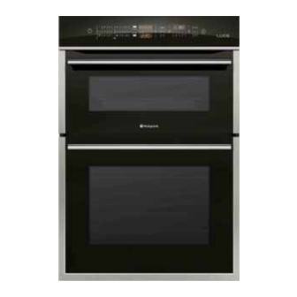
Page 7: Product Image
Indesit Company PRODUCT IMAGE Control Panel MODEL & SERIAL NUMBER LABEL - Record the Model No. and the Serial No. Grill Element on back page. Oven Light Stay Clean Liners* & Wirework Shelf Grill Pan & Supports Food Support* Inner Door Glass... -
Page 8: Installation Instructions
Indesit Company INSTALLATION Electrical Requirements This equipment is designed specifically for domestic purposes and the Company cannot accept responsibility if it is used in any other type of installation. For your own safety, the Company recommends that the appliances are installed by a competent person - such as one who is registered with NICEIC (National Inspection Council for Electrical Installation Contracting). - Page 9 Indesit Company d. The air gap at the rear allows the warmed air to pass out of the inner cabinet space but where it is intended to fit cupboards above the oven unit it is essential that the warmed air is exhausted through the front of the cabinet.
- Page 10 Indesit Company INSTALLATION DIAGRAMS Ventilation Slot required Fig. 1 here if cabinet does not fit to ceiling -51mm x 457mm min. area Ventilation Slot required here if the cabinet does fit to the ceiling - 51mm x 457mm min. 50mm...
- Page 11 Indesit Company 562mm Fig. 3 Viewed down through cabinet Cabinet No. 6 x 25mm screw (4 supplied) 870mm Oven Door Fig. 2 Fig. 4 882mm, 870mm if cooker trim is to Connector overlap Cable top edge of shelf if hob fitted...
-
Page 12: Oven Temperature Test Procedure
Indesit Company TEST PROCEDURE FOR OVEN TEMPERATURE MEASUREMENTS The following is the preferred method to be used when calculating any Mean Oven Centre Temperature (M.O.C.T.). Equipment: - Surface Temperature Probe Part No. 5600081 Digital Thermometer Part No. 5700036 Thermocouple Part No. 5700066 Temperature Test Gate Part No. - Page 13 Indesit Company CONTROLS TEMPERATURE END OF COOKING PREHEATING / RESIDUAL HEAT icon icon DURATION icons icon CONTROL MANUAL TIME TEMPERATURE display PANEL LOCK COOKING MODE display icon icons TIME / LIGHT START / CONTROL PANEL POWER BUTTON TEMPERATURE icon STOP...
- Page 14 Indesit Company Setting the Minute Minder The minute minder may be set regardless of whether the oven is switched on or off. It does not switch the oven on or off. When the set time has elapsed, the timer emits a buzzer that will automatically stop after 30 seconds or when any active button on the control panel is pressed.
-
Page 15: The Controls
Indesit Company There is no preheating stage for the GRILL mode. Never put objects directly on the bottom of the oven; this will prevent the enamel coating from being damaged. Always place cookware on the rack(s) provided. If the oven is in Auto Cook or Demo mode, to switch the oven off, press and hold the On/Off button. - Page 16 Indesit Company THE OVEN MODES IN MORE DETAIL The oven is equipped with a number of different cooking modes. Manual Cooking Modes All cooking modes have a default cooking temperature which may be adjusted manually to a value between 30°C and 250°C for TOP OVEN, between 80°C and 230°C for MAIN OVEN, (for GRILL mode - from 5% to 100%).
- Page 17 Indesit Company AUTOMATIC COOKING MODES The temperature and the cooking duration are preset values, guaranteeing a perfect result every time - automatically. These values are set using the C.O.P.® (Programmed Optimal Cooking) system. The cooking cycle stops automatically and the oven indicates when the dish is cooked. You may start cooking whether the oven has been preheated or not.
-
Page 18: Practical Cooking Advice
Indesit Company PROGRAMMING COOKING A cooking mode must be selected before programming can take place. In both TOP and MAIN ovens for the manual cooking programs it is possible to set the cooking time from 00:01 to 23:59. For the automatic cooking functions the cooking time is imposed automatically and can be altered only by 5 to 20 minutes, depending on the cooking programme. -
Page 19: Solarplus Grill
Indesit Company SOLARPLUS GRILL MAXIMUM is the hottest setting and MINIMUM the coolest. GRILLING SHOULD NOT BE UNDERTAKEN WITH THE TOP OVEN/GRILL DOOR CLOSED - this will cause overheating. To operate the grill proceed as follows: 1. Open the grill/top oven door fully. -
Page 20: Top Oven - Conventional Cooking
Indesit Company TOP OVEN - CONVENTIONAL COOKING The heat for conventional cooking in the top oven is provided by the grill element and the element under the floor of the oven. It is ideal for the slow cooking of cheaper cuts of meat in casseroles etc. -
Page 21: Main Oven - Intelligent Cooking System
Indesit Company MAIN OVEN - THE INTELLEGENT COOKING SYSTEM The main oven of your new cooker is equipped with an intelligent electronic cooking system that gives you additional cooking performance, flexibility and features over traditional cooking products. See cooking charts for temperatures and shelf positioning. -
Page 22: Cooking Advice Tables
Indesit Company COOKING ADVICE TABLES Cooking Advice Table OOK HART - Traditional mode: OOK HART - Fan oven mode: Shelf Meat Pre-heat Temperature ooking Time Meat Pre-heat Temperature ooking Time Position Beef 190/200°C 2 or 3 20-25 minutes per 450g (1lb) + 20 minutes extra... -
Page 23: Care & Cleaning
Indesit Company CARE & CLEANING The following information had been complied using sections of the customer handbook supplied with the appliance. WARNING: - BEFORE CLEANING, SWITCH THE COOKER OFF AT THE COOKER CONTROL PANEL AND ALLOW IT TO COOL. IT IS ESSENTIAL THAT THE OVENS ARE CLEANED AND KEPT FREE FROM FATS, OIL AND GREASE. - Page 24 Indesit Company Cleaning The Doors Take particular care not to damage the inner surface of the door inner glass that is coated with a heat reflective layer. Do not use scouring pads or abrasive powder which will scratch the glass.
-
Page 25: Auto-Test
Indesit Company AUTO-TEST Start with the oven off and oven door closed. Key '+', Key '–', Key '+'. Press and hold the 'clock' key for 5 seconds (a beep will sound to confirm the selection). Press “Start” (a beep will sound to confirm the selection). -
Page 26: Fault Codes
Indesit Company FAULT CODES FAULT SUBCODE DESCRIPTION CHECKS Main PCB probe short circuited. Main PCB probe circuit open. Rtn out of range Vline out of range No mains voltage / Master Relay Fans open Mains voltage present / Master Relay Fans shortcircuited /(Fan triac short circuited). - Page 27 Indesit Company FAULT CODES FAULT SUBCODE DESCRIPTION CHECKS 1 Check the PTC probe in the top cavity is working No gradient for main oven probe. properly. Top oven probe short circuited. 2 Check connectors on the board and component F53** Top oven probe circuit open.
- Page 28 Indesit Company FAULT CODES FAULT SUBCODE DESCRIPTION CHECKS Communication- MAIN Communication - VISUAL C o m m u n i c a t i o n 1 Unplug, wait for 2 minutes, plug back in again and A L I G N M E N T W I T H M A I N test the appliance.
- Page 29 Indesit Company FAULT CODES FAULT SUBCODE DESCRIPTION CHECKS Tangential fan in diode mode. Tangential fan short circuited or disconnected. Tangential fan circuit open. Tangential fan FB failure. Tangential fan general failure. 1 Check that the tangential fan is working properly.
-
Page 30: Servicing & Dismantling Instructions
Indesit Company SERVICING & DISMANTLING INSTRUCTIONS SAFETY NOTES: 1) Disconnect the appliance from the electricity supply before commencing any work. 2) Beware of sharp edges on metal, plastic and glass parts. 3) Carry out insulation resistance, continuity and functional tests on the appliance after service. - Page 31 Indesit Company Main Power Board Remove the top panel as in 1). Depress the tabs securing the power board to the mounting bracket. Noting all the connections, lift the power board away. Reassembly in reverse order. To Access the Lamp Body & Fan Motor Remove the top panel as in 1).
- Page 32 Indesit Company 12) Base Element - Top Oven & Main Oven Remove the right hand side panel, 5 screws). Top Oven - Loosen the lagging wire, lift up the top cavity lagging and carefully pull out the lagging between the two cavities.
- Page 33 Indesit Company 15) Main Oven Circulaire Oven Element Remove the oven furniture. Remove the main oven inner rear panel (4 screws). Remove the element retaining screw on the rear panel. Remove the 3 screws from the element retaining clips. Disengage the element from the element retaining bracket.
- Page 34 Indesit Company 17) Inner & Centre Door Glasses Remove the Inner Glass as Follows: - Open the door fully and remove the top extrusion, removing the screws from both sides of the door. Gently ease the top trim away from...
- Page 35 Indesit Company Feed the replacement sensor wire back through the oven cavity and fit the sensor retaining screw inside the cavity. Channel the wire up and fit to the power board. 10. Gather up the previously released wires and cable tie together. Reassemble in reverse order.
-
Page 36: Wiring Harness
WIRING HARNESS 13 16 WHITE 1.0 X 1410 1 2 3 4 5 T/O BASE ELEMNET J14 (1) VIOLET 1.0 X 840 VHR-5M TOP GRILL RH J14 (2) BROWN 1.5 X 840 J14 (3) TOP GRILL RH BROWN 1.0 X 920 T/O BASE ELEMNET BLACK 1.5 X 1070 MO N... -
Page 37: Wiring Diagram
Indesit Company WIRING DIAGRAM HARDWARE KEY CONNECTION To DISPLAY BOARD 3550 04 K30 P196 3550 04 K41 3550 05 K30 4 3 2 1 POT 2 POT 1 VCC 2 DOOR SWITCH LED 2 LED 1 DIVIDER DOOR TOP OVEN... -
Page 38: Programming
(different types exist) NOTE: This version of the Hardware Key and Eeprom Writer programmes are only available to Indesit Company Engineers. Pre-programmed Eeproms and Service socket boards are available for repairs and spare parts. PROGRAMMING (using Smart Card Reader / Card) - Page 39 Indesit Company Connect the machine to the Electrical supply, the LEDs on the Smart Card Reader will light in this sequence: ON: Good Communication between Smart Card Reader and Card. OFF; Green Blinking: Download taking place. At end, Green ON ---> Download OK.
Need help?
Do you have a question about the HOTPOINT LUCE DX1032CX and is the answer not in the manual?
Questions and answers