Advertisement
Quick Links
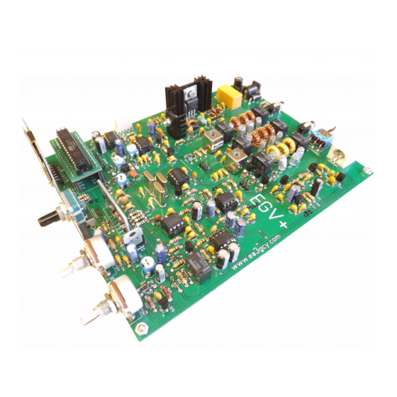
DB4020
Dual Band 40&20m QRP SSB transceiver
KIT
Assembly manual
Last update May 20, 2020
ea3gcy@gmail.com
www.ea3gcy.com
:
Latest updates and news in
DB4020
Thank you for building the
Dual Band 40&20M SSB Transceiver kit
Have fun assembling it and enjoy QRP! 73 Javier Solans, ea3gcy
DB4020 Dual Band 40&20M SSB QRP Transceiver Kit
Page 1
Advertisement

Related Manuals for EA3GCY DB4020


Summary of Contents for EA3GCY DB4020
- Page 1 Latest updates and news in DB4020 Thank you for building the Dual Band 40&20M SSB Transceiver kit Have fun assembling it and enjoy QRP! 73 Javier Solans, ea3gcy DB4020 Dual Band 40&20M SSB QRP Transceiver Kit Page 1...
-
Page 2: Table Of Contents
INDIVIDUAL PARTS LIST………………..….………….………………….…………….…….… 9 240-QUADRANT COMPONENT LAYOUT MAP ..............13 ASSEMBLY ………………..……………….…..……………………………………....14 ADJUSTMENT AND TESTING…………..…….……………………………….…………..28 IF YOUR KIT DOES NOT WORK AFTER COMPLETING ASSEMBLY ….………….……. 32 LIMITED WARRANTY.....…………………………………………………………..... 33 SCHEMATIC.…..……………………..……….……………………………………………..…. WIRING………………………...………………………………………………………………….. DB4020 Dual Band 40&20M SSB QRP Transceiver Kit Page 2... -
Page 3: Introduction
INTRODUCTION The DB4020 is a design based on the NE602 integrated circuit used as a receiving SSB mixer and demodulator and SSB generator and transmission mixer. Band and TX / RX switching, audio mute etc. they are controlled by an Arduino Nano. -
Page 4: Specifications
IF frequency: 4.915MHz. AGC: acts on the receive path according to the received audio. Audio output: 250mW, 4-8 ohms. PLEASE READ ALL ASSEMBLY INSTRUCTIONS COMPLETELY AT LEAST ONCE BEFORE YOU BEGIN. DB4020 Dual Band 40&20M SSB QRP Transceiver Kit Page 4... - Page 5 “U” printed on the circuit board. Finally, pin 1 of the IC is also marked with a small dimple or dot; this end of the IC should be oriented towards the notch in the IC socket or the "U" of the component outline. DB4020 Dual Band 40&20M SSB QRP Transceiver Kit Page 5...
- Page 6 Look for the most appropriate moment to do it, and most importantly, take your time. The drawings, photos and instructions in the manual will illustrate and make the process easier. DB4020 Dual Band 40&20M SSB QRP Transceiver Kit Page 6...
- Page 7 C4, C57 (elect.) C90 (elect.) 4.7uf 10uf C7, C25, C51, C76, C77, C82, C97, C102 (elect.) 10uf 47uf C91 (elect.) 47uf 100uf C71, C83, C85 (elect.) 100uf 220uf C87 (elect.) 220uf DB4020 Dual Band 40&20M SSB QRP Transceiver Kit Page 7...
- Page 8 7 pin 45° bent strip (to SI5351 module) Jumper Jumpers to J1, J2 and J3, J4 (IF Rx filter jumpers). Heatsink Heatsink to Q3 Heatsink Heatsink to Q2 Mica insulator Mica insulator to Q2 and Q3 DB4020 Dual Band 40&20M SSB QRP Transceiver Kit Page 8...
- Page 9 M3 washer Metal M3 washer to Q2 and Q3 M3 spacers Hex 5mm M3 spacers 217 cms. 217 cms. 0,5mm enamelled wire Microphone Electret Microphone Capsule DB4020 PCB (printedcircuitboard) DB4020 DB4020 Dual Band 40&20M SSB QRP Transceiver Kit Page 9...
- Page 10 C-13/14 470 Ω yellow-violet-brown VFO input 10 Ω brown-black-black BFO input 150 Ω brown-green-brown BFO input O-8/9 100 Ω brown-black-brown BFO input 150 Ω brown-green-brown BFO imput brown-black-orange Arduino nano DB4020 Dual Band 40&20M SSB QRP Transceiver Kit Page 10...
- Page 11 40m LPF D/E-5 270p Polystyrene 270J 40m LPF 180p Polystyrene 180J 20m LPF 390p Polystyrene 390J 20m LPF 390p Polystyrene 390J 20m LPF D/E-7 180p Polystyrene 180J 20m LPF 40m BPF DB4020 Dual Band 40&20M SSB QRP Transceiver Kit Page 11...
- Page 12 Arduino nano (R-3) C104 100n SMD pre-soldered on bottom Arduino nano (R-6) C105 100n SMD pre-soldered on bottom Arduino nano (R-7) C106 100n SMD pre-soldered on bottom Arduino nano (Q-2) DB4020 Dual Band 40&20M SSB QRP Transceiver Kit Page 12...
- Page 13 47V Zener diode Output Amp 1N4148 4148 E-10/11 1N4148 4148 E-11 6.2V Zener diode IC4 and IC5 supply K-9/10 1N4148 4148 S-Meter Q-13 1N4148 4148 S-Meter Q-12 1N4148 4148 RIT path O-1/2 DB4020 Dual Band 40&20M SSB QRP Transceiver Kit Page 13...
- Page 14 Omron G5V-1 12V Band switch D-8/9 Omron G5V-1 12V Band switch Omron G5V-1 12V Band switch Omron G5V-1 12V TX / RX path Omron G5V-1 12V TX / RX path DB4020 Dual Band 40&20M SSB QRP Transceiver Kit Page 14...
-
Page 15: 240-Quadrant Component Layout Map
252-QUADRANT COMPONENT LAYOUT MAP DB4020 Dual Band 40&20M SSB QRP Transceiver Kit Page 15... -
Page 16: Assembly
The values which are in decade increments can be easily confused, such as 470, 4K7 and 47K, so be sure to verify the colors before soldering the component in place! If you are in doubt, use a multimeter to check the resistance value. DB4020 Dual Band 40&20M SSB QRP Transceiver Kit Page 16... - Page 17 Q3 as shown in the image. D3 is also a Zener diode (thicker than the others); it is marked 47V. Diode D19 is a BY255, black, much thicker than the others. DB4020 Dual Band 40&20M SSB QRP Transceiver Kit Page 17...
- Page 18 The electrolytic capacitors must be placed with the correct orientation: the LONG LEAD goes in the hole labeled “+” and the SHORT LEAD is "-", indicated by a band containing "-" signs on the side of the capacitor. DB4020 Dual Band 40&20M SSB QRP Transceiver Kit Page 18...
- Page 19 CW Interface and filter (see images) Jumper on RX IF crystal filter input Jumper on RX IF crystal filter output DB4020 Dual Band 40&20M SSB QRP Transceiver Kit Page 19...
- Page 20 This is an important task; it should be done exactly as shown in the images. DB4020 Dual Band 40&20M SSB QRP Transceiver Kit Page 20...
- Page 21 Mount the sockets for IC1, IC2, IC4, IC5, IC6 and IC7 in the locations printed on the circuit board. Make sure that the sockets lie flat against the circuit board. Next, insert IC1, IC2, IC4, IC5, IC6 and IC7 into their respective sockets. DB4020 Dual Band 40&20M SSB QRP Transceiver Kit Page 21...
- Page 22 They are RF transformers for the bandpass filters. Make sure that they lie flat against the circuit board. In order to solder the tabs of the shield, you will need to hold the soldering iron a little longer on the joint. DB4020 Dual Band 40&20M SSB QRP Transceiver Kit Page 22...
- Page 23 Counting the turns: Count one turn for each pass of the wire through the center of the toroid. Important: Wind the toroid exactly as shown in the images. One turn more or less will affect the operation and the output power. DB4020 Dual Band 40&20M SSB QRP Transceiver Kit Page 23...
- Page 24 For L13 cut about 26cm (10.5”) of 0.5mm diameter enameled wire and wind seventeen (17) turns. Mount and solder the three toroids in place. DB4020 Dual Band 40&20M SSB QRP Transceiver Kit Page 24...
- Page 25 Counting the turns: Count one turn for every pass of the wire through the center of the toroid. Note: If you need to, you can remove the Q2 heatsink or use small tweezers to help you insert the toroid into place. DB4020 Dual Band 40&20M SSB QRP Transceiver Kit Page 25...
- Page 26 9.5mm/0.375in outer diameter) is used. It has 8 + 8 turns. - Cut a 31-32cm (12”) long piece of 0.5mm diameter enameled wire. - Bend the wire in half. - Twist it so that there are two twists per cm. DB4020 Dual Band 40&20M SSB QRP Transceiver Kit Page 26...
- Page 27 - Using a multimeter in its ohm or continuity function, locate and mark the ends, identifying them as “a” - “a1” and “b” - “b1”. - Mount the toroid into the appropriate holes as marked on the circuit board. DB4020 Dual Band 40&20M SSB QRP Transceiver Kit Page 27...
- Page 28 Before mounting the external connection jacks, you should cut the protrusions located at the bottom of these jacks; otherwise you will not be able to solder them in the correct position. See the image. DB4020 Dual Band 40&20M SSB QRP Transceiver Kit Page 28...
- Page 29 IC11 OLED 1.3” display This is the display for the DB4020. It may be best not to place it to the end. Before placing it, you must think and be sure how to install the DB4020 in your enclosure. The OLED display use a strip of 7 pins at right angles to solder the module onto the board.
- Page 30 You may prefer to install the OLED display, encoder and potentiometers outside the board. Then see the section "WIRING AND CONNECTIONS" IC12 Arduino NANO Install the two 15-pin female strips and insert the Arduino UNO module as shown in the image. DB4020 Dual Band 40&20M SSB QRP Transceiver Kit Page 30...
- Page 31 - DO NOT yet connect a microphone. - Apply power (remember J1 jumper plugged). - The screen should light up and show the main menu. See section: Using the DB4020. - Turn the volume to maximum; you should hear a light background noise.
- Page 32 You can now increase the P1 setting for the power of your choice. Depending on the sensitivity of the microphone, you can adjust the P1 to the maximum. For microphone wiring see “DB4020 Microphone” on “ANNEXES” section. Normally P1 will be adjusted to mid-position.
- Page 33 M DB4020 icrophone for The DB4020 need a condenser electret microphone (electret capsule included on kit). You can use an electret microphone for amateur radio or build your own mic. The wiring is very simple: Note about electret capsules: The connections of all capsules have polarity “+”...
- Page 34 Antennas. To obtain a good performance of the DB4020 it is essential to use a specific antenna for the 7Mhz and 14MHz band. You can use a ham radio antennas from factory. Or you can build your own dipoles antennas for very little money and that will give you very good results.
- Page 35 However, for each assembly some slight re-adjustments can be made in the display settings menu. Please, download the “DB4020 User Manual” from the website: www.qrphamradiokits.com DB4020 Dual Band 40&20M SSB QRP Transceiver Kit...
-
Page 36: If Your Kit Does Not Work After Completing Assembly
I please follow these steps in order: will try to keep the cost as moderate as possible (see the “FAQ” page of the EA3GCY kits website). DB4020 Dual Band 40&20M SSB QRP Transceiver Kit Page 36... -
Page 37: Limited Warranty
Enjoy QRP! components correctly, good 73 Javier Solans, EA3GCY workmanship and proper tools and instruments in the construction and adjustment of this kit. DB4020 Dual Band 40&20M SSB QRP Transceiver Kit Page 37... -
Page 38: Schematic
SCHEMATICS DB4020 Dual Band 40&20M SSB QRP Transceiver Kit Page 38... - Page 39 DB4020 Dual Band 40&20M SSB QRP Transceiver Kit Page 39...
-
Page 40: Wiring
WIRING AND CONNECTIONS The DB4020 only requires wiring of the microphone, PTT and speaker internal to the microphone (if using a speaker-mic) or a speaker installed inside the transceiver enclosure. You can use an external speaker cabinet connected to the rear "SPEAKER" jack socket.
Need help?
Do you have a question about the DB4020 and is the answer not in the manual?
Questions and answers