Table of Contents
Advertisement
Quick Links
Advertisement
Table of Contents
Troubleshooting

Related Manuals for Barco Event Master E2 Series


Summary of Contents for Barco Event Master E2 Series
- Page 1 Event Master Devices User's Guide ENABLING BRIGHT OUTCOMES...
- Page 2 Barco Inc, Image Processing 3078 Prospect Park Drive, Rancho Cordova, CA , 95670, USA www.barco.com/en/support www.barco.com Registered office: Barco NV President Kennedypark 35, 8500 Kortrijk, Belgium www.barco.com/en/support www.barco.com...
- Page 3 Barco. If the purchaser or a third party carries out modifications or repairs on goods delivered by Barco, or if the goods are handled incorrectly, in particular if the systems are operated incorrectly or if, after the transfer of risks, the goods are subject to influences not agreed upon in the contract, all guarantee claims of the purchaser will be rendered invalid.
- Page 4 Changes or modifications not expressly approved by the party responsible for compliance could void the user's authority to operate the equipment FCC responsible: Barco Inc. 3059 Premiere Parkway Suite 400 30097 Duluth GA, United States Tel: +1 678 475 8000 EN55032/CISPR32 Class A Multimedia Equipment Warning: This equipment is compliant with Class A of CISPR 32.
-
Page 5: Table Of Contents
Table of contents 1 Introduction........................................13 About this guide ....................................14 Record of changes ..................................14 Symbols, pictures and fonts..............................19 The 4K screen management system...........................19 2 Safety ..........................................21 General considerations ................................22 Important safety instructions..............................22 3 General..........................................25 Event Master devices overview ..............................26 Event Master series processors features..........................31 Event Master controllers features............................37 Terms and definitions..................................39 Control overview....................................42... - Page 6 4.15 CXP Input/Output Card................................79 4.16 VPU Card ......................................81 5 Front Panel Menu orientation ..............................83 Power-up initialization ..................................84 Front Panel menu tree .................................84 Using menu system ..................................85 About Status menu..................................88 About Setup menu..................................88 About the System menu................................89 System menu > Black Invalid..............................89 System menu >...
- Page 7 6.31 Programming Menu > Adjustment area > Source adjustment ................237 6.32 Programming Menu > Adjustment area > Global Transition Rate/Trans/Cut ..........239 6.33 Cue Menu......................................240 6.34 Cue Menu > Adjustment area ............................... 241 6.35 Cue Menu > Cue Workspace area............................. 242 6.36 Cue Menu >...
- Page 8 10.14 Transition buttons ..................................341 10.15 Future Expansion Button Group (EC-200/EC-210 only)..................342 10.16 Direct Selection Button Group and Barco Eye Button (EC-200/EC-210 only) .......... 342 10.17 System Function Button Group (EC-200/EC-210 only)..................344 10.18 Syntax Entry Button Group (EC-200/EC-210 only) ....................345 10.19 Contextual Display Button Group (EC-200/EC-210 only) ..................
- Page 9 12.5 How to use the Layer buttons ............................... 362 12.6 What are Layer executers? ..............................363 12.7 How to use assign buttons..............................363 12.8 How to use the page arrow buttons ........................... 364 12.9 How to use transition buttons..............................364 12.10 How to use the T-bar..................................
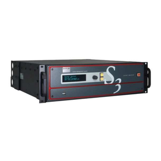
- Page 10 14.35 Top Card Guide ..................................... 441 14.36 Motherboard Fan ..................................442 15 S3 Maintenance....................................445 15.1 S3 unit Overview ..................................447 15.2 Process Overview..................................448 15.3 Spare Parts Serviceable by All Users ..........................449 15.4 Rear I/O, Link and VPU Cards.............................. 450 15.5 Rear I/O, VPU and Link card Heatsink Fan........................
- Page 11 17.1 Servicing ......................................520 18 EC-50 Maintenance ..................................521 18.1 Servicing ......................................522 19 EC-200/EC-210 Maintenance............................... 525 19.1 Servicing ......................................526 20 Environmental information................................ 529 20.1 Disposal information................................... 530 20.2 RoHS compliance..................................530 20.3 Contact information..................................531 A Specifications ......................................533 Specifications of E2 ..................................
- Page 12 R5905948 /12 Event Master Devices...
-
Page 13: Introduction
Introduction About this guide..........................14 Record of changes........................14 Symbols, pictures and fonts......................19 The 4K screen management system ....................19 R5905948 /12 Event Master Devices... -
Page 14: About This Guide
The manual also includes all the necessary instructions on how to upgrade firmware, install spare parts and perform any hardware upgrades. Barco provides a 3-year parts and labor warranty for all hardware components. Please refer to Appendix E (“Warranty”, page 575) for specific details regarding the warranty terms. - Page 15 Introduction Changes Revision • EC–50 product has been added. Chapters concerned by this new controller have been modified or added: Description in General chapter. New chapters dedicated to Controller Orientation, Controller Configuration and Controller Operation. • A new version of Event Master Toolset is available (V2.0). The GUI orientation chapter and the System setup procedure have been updated.
- Page 16 Introduction Changes Revision Descriptions of the subtabs in the Settings Menu, Resources area, see “Settings Menu”, page 253. Soft-Off button in the EC-200 GUI, see “How to power down and restart the EC- 200/EC-210”, page 360. Split-Mode configuration, see “Configuration Menu > System diagram area”, page 112.
- Page 17 Introduction Changes Revision output cards and split-mode on the quad-channel DisplayPort output card and the tri-combo output card. Added instructions for creating Super Destinations: refer to “Configuration Menu > Adjustment > Destination Configuration”, page 145 and also to “Programming Menu”, page 196 and “Programming Menu > Adjustment area > Dest Group configuration”, page 228.
- Page 18 Menu > Adjustment > Custom Formats Configuration”, page 172, and see the “Custom Format Adjust tab – bottom half” subsection. Added +Add Barco Projector and +Add Event Master XML buttons to the External Devices tab. Refer to “Configuration Menu > Adjustment > External Devices Configuration”, page 175, and see the “External Devices tab”...
-
Page 19: Symbols, Pictures And Fonts
Introduction Changes Revision Added support for E2-Gen2 video processor. Refer to “Event Master devices overview”, page 26, and see the “About E2 Gen 2” subsection. Added support for 4K Quad HDMI 2.0 Output card as a Multiviewer. Added CXP Input/Output card. Refer to “CXP Input/Output Card”, page 79. 1.3 Symbols, pictures and fonts Symbol overview The following icons are used in the manual :... - Page 20 Introduction systems. Multiple users can control a system simultaneously, and the API allows third-party developers to create custom control programs and interfaces. Thanks to their modular designs, users can simply add a new input or output card to support future signal interfaces. This modularity also ensures great serviceability, as users can easily swap a specific input or output card in the case of damage, without needing to ship or replace the entire box.
-
Page 21: Safety
Safety General considerations .........................22 Important safety instructions......................22 About this chapter Please read this chapter carefully. It contains important information to prevent personal injury while installing and operating Event Master devices. Furthermore, it includes several cautions to prevent damage to the Event Master devices. -
Page 22: General Considerations
Safety 2.1 General considerations General safety instructions • Before operating these devices please read this manual thoroughly and retain it for future reference. • All warnings in the documentation manual should be adhered to. • All instructions for operating and use of these devices must be followed precisely. •... - Page 23 Refer cord and connector changes to qualified service personnel. • Replace spare parts only with the same parts supplied by Barco. • Save the original shipping carton and packing material. They will come in handy if you ever have to ship your equipment.
- Page 24 Safety R5905948 /12 Event Master Devices...
-
Page 25: General
General Event Master devices overview......................26 Event Master series processors features ..................31 Event Master controllers features....................37 Terms and definitions ........................39 Control overview...........................42 Presentation System overview.......................43 Installation requirements .......................44 Initial inspection..........................44 Rack-Mount Procedure .........................49 About this chapter This chapter is designed to introduce you to the Event Master series products. R5905948 /12 Event Master Devices... -
Page 26: Event Master Devices Overview
General 3.1 Event Master devices overview General Event Master devices are the most advanced video processing and presentation control systems on the market today. These systems provide source selection, advanced windowing features, seamless switching, video effects and integrated control for professional video presentations. Thanks to their modular and scalable architecture, Event Master devices can support a wide variety of show configurations. - Page 27 General About E2 Gen 2 Image 3-2: E2 Gen 2 With up to 40 inputs and 18 outputs, the E2 Gen 2 processor provides full screen control. The E2 Gen 2 offers 16 4K inputs and 8 4K outputs enabling impressive pixel processing power with increased processing speed. Whether native or scaled inputs, single cable 4K60p, two connectors or four, this HDCP-compliant system manages it all.
- Page 28 General About EX Image 3-4: EX When linked to the Event Master system (E2 or S3– 4K) it acts as an input and/or output expansion box to increase the capacities available to the system. Via the link cable, a fiber extension can be used to extend the distance between the EX and the E2 or S3 processor.
- Page 29 General About EC-30 Image 3-7: EC-30 The EC-30—the most compact version of the EC-series Event Master controllers—provides instant access to the most crucial features for everything from a tradeshow booth to a large corporate event, even a music tour. The EC-30 offers a compact surface, simplified workflow, and fingertip control where budget and space are the deciding factors.
- Page 30 Event Master compatible devices over network and USB. EC-210 is the infrastructure that will keep you in control of Barco Event Master series devices, now and in the future. R5905948 /12...
-
Page 31: Event Master Series Processors Features
General In our efforts to support our existing customers and respect their investment, we have created an upgrade kit that takes any EC-200 to the same functionality and capacity as a factory assembled EC-210, with only minor cosmetic differences. 3.2 Event Master series processors features Inputs Model E2 Gen 2... - Page 32 General Inputs via input cards Model 4x HDMI 1.4 (297 Mpix/sec max) 4x DisplayPort 1.1 (300 Mpix/sec max) S3–4K Jr. • 8 inputs via 2 Event Master Series 1x input cards: Up to 2x 4K inputs – each input card supports up to 1x 4K@60p 4x SD/HD/3G SDI 2x HDMI 1.4 (297 Mpix/sec max) 2x DisplayPort 1.1 (300 Mpix/sec max)
- Page 33 General Outputs via output cards Program outputs Model E2 Gen 2 • Up to 18 output connectors among 4 • Sixteen (16) program outputs output cards (Event Master Series 2 configurable as single screens or tiled/ cards): blended widescreens Up to 8x 4K outputs – each output Configurable from 16x card supports up to 2x 4K@60p 2048 ×...
- Page 34 General Outputs via output cards Program outputs Model S3–4K Jr. • Up to 8 outputs via 2 output cards (Event • Eight (8) program outputs configurable Master Series 1 cards): as single screens or tiled/blended widescreens Up to 2x 4K outputs – each output card supports up to 1x 4K@60p Configurable from 8x 2048 ×...
- Page 35 General Background mixer Each PGM screen destination has an unscaled seamless background mixer supporting the full resolution of the destination • Any live input type can be a background source • Matte color generator • Still store as background Destinations (single chassis) Model Destinations E2 or E2 Gen 2...
- Page 36 General Aux Scaling Mode Max. number of 4K outputs Max. number of Dual-Link Max. number of HD (2K) Model outputs outputs E2 Gen 2 • 8x Scaled AUX output • 16x Scaled AUX output • 18x Scaled AUX output • 8x Scaled AUX output •...
-
Page 37: Event Master Controllers Features
General The S3–4K Jr. comes with a single power supply; the redundant power supply is optional. 3.3 Event Master controllers features Connectivity EC-30 EC-50 EC-200 EC-210 USB connection from USB connection from • 4 USB connectors in • 4 USB connectors in Event Master Toolset Event Master Toolset, the back can be used... - Page 38 1 Live Function Button Group • 1 Arrow Button Group • 1 Trackball with 4 modifier buttons • 2 Barco Eye Buttons • 5 Rotary Encoders referred to as wheels with modifier buttons • 1 Future Expansion Button Group* •...
-
Page 39: Terms And Definitions
General Other EC-30 EC-50 EC-200/EC-210 • USB port for connection to host • 1x work light (flexible support) • 2x work lights (flexible support) computer • 2x flexible ribbon LED (backlight • 2x flexible ribbon LED (backlight • Status LEDs and color coded in front face and back face) in front face and back face) LCD displays... - Page 40 General DA (Distribution Amplifier) A video device that inputs one video signal, and outputs multiple “identical” signals. Destination (DST) A Destination is a location to which you can route the output of an Event Master device. A destination can be configured as a group of one or more outputs that feed the same screen.
- Page 41 General Linear Key Linear key is a keying mode in which the edges of anti-aliased key sources (such as character generators) are reproduced clearly. Typically, two separate signals are required from a linear key source: a cut and a fill. Menu A term used to describe buttons and functions on the high-resolution color LCD touch screen.
-
Page 42: Control Overview
Event Master Toolset running on a Windows 7, 8.1, or 10 PC or Apple Mac with OSX. • EventMaster Controller EC-30/EC-50 or EC-200/EC-210. Remote recall and non-Barco device connectivity: • External ASCII protocol connected devices like PresetManager. Not all of these do the same thing, below the immediate differences. Several of these all work at the same time, providing multiple points of control. -
Page 43: Presentation System Overview
General In addition, since the configuration parameters and presets are stored on the Event Master processor unit, multiple instances of the GUI can be run simultaneously on different computers expanding the control possibilities. Refer to the chapter “EM GUI orientation”, page 103 for more information about the GUI. Subsequently in this User's Guide, the Event Master Control Software will be referred as the EM GUI. -
Page 44: Installation Requirements
Software package Verify that the Event Master device is loaded with the latest software version available on the Barco web site (URL:https://www.barco.com/). Refer to the chapter “Updating firmware”, page 301 for more information about the device upgrading software. - Page 45 Save the original shipping case and packing material, these will be necessary if you ever have to ship your device. For maximum protection, repack your device as it was originally packed at the factory. When shipping an E2 in a Barco-supplied case, make sure that the rear connector protectors are installed to prevent damage. Box content After unpacking an Event Master device, it is recommended that it be checked to see if all accessories were included.
- Page 46 General Product Contains Accessories included • 2x 09-0106032-91 • Rear Rack Mount Support Plates • 8x 13-0081012-90 • 8-32 x .38 Pan Head Screws for Rear Rack Mount Support Plates • 2x 09-0106031-90 • Rear Rack Mount Brackets • 07-1205500-00 •...
- Page 47 General Product Contains Accessories included R9004778 • 3RU rack mount • S3 Jr. assembly chassis (S3–4K Jr.) • 1x 14-9750004-90 • European Power Cord CEE7 (not included with units shipped to China) • 1x B1959864 • US Power Cord NEMA 5/15 (not included with units shipped to China) •...
- Page 48 General Product Contains Accessories included • 1x 90409546EF • USB Type A to Type B Cable • 07-1205500-00 • USB Thumb Drive (Contains Users Guide, System Software and Control GUI) • R5906018 • Safety manual • 60600356 • Quick Start Guide R9004772 •...
-
Page 49: Rack-Mount Procedure
Quick Start Guide Mechanical check This check should confirm that there are no broken parts and the unit is free of dents or scratches. Your Barco Sales representative should be notified as soon as possible if this is not the case. - Page 50 General Measure the distance between the front and rear rack rails. Remove the four mounting screws that secure each side rail to the E2, and then adjust the spacing of each side rail as necessary. Image 3-13 Chassis rear Side rail Mounting screws Re-install the mounting screws.
- Page 51 General Tighten the two lower screws, then install and tighten the two uppers screws in the rack rail. How to install S3 or EX in a rack Use the following steps to rack mount the S3 or the EX: S3 and EX units are shipped with side rails included in the shipping case and not installed onto the chassis. These side rails, when they are properly installed and adjusted, assist with the distribution of chassis (and cable) weight within your rack.
- Page 52 General R5905948 /12 Event Master Devices...
-
Page 53: Hardware Orientation
Hardware orientation Front panel...........................54 Rear panel ...........................55 SDI Input Card ..........................60 Dual Link DVI Input Card.......................62 HDMI/DisplayPort Input Card......................64 Quad Channel DisplayPort 1.2 Input Card ..................65 Quad HDMI 2.0 Input Card ......................67 Tri-Combo Input Card ........................68 Quad Channel DisplayPort 1.2 Output Card..................70 4.10 HDMI Output Card ........................72 4.11 Quad HDMI 2.0 Output Card ......................73 4.12 SDI Output Card ...........................74... -
Page 54: Front Panel
See Image 4-1 for an illustration of the front panel of Event Master E2 (and E2 Jr.) and S3–4K (and S3–4K Jr.) series processors. See Image 4-2 for an illustration of the front panel of the Event Master EX processor. Image 4-1: E2 and S3 series front panel Barco logo Power ON/OFF button Display screen... -
Page 55: Rear Panel
Hardware orientation Image 4-3: e.g. E2 display screen. Menu navigation controls The navigation in the menus is assumed by three controls: • Turn the ADJUST knob to scroll through the menu items on the screen. Turn the knob counter-clockwise to scroll down. Turn the knob clockwise to scroll up. - Page 56 Hardware orientation Image 4-5: E2 and S3–4K series rear panels AC connectors VPU cards RJ-45 connector for 10/100/1000 BaseT Ethernet Input cards (HDMI/DP, SDI, DVI) communications Outputs cards (DVI, SDI) Genlock Input BNC with passive Loop-through Multiviewer card (HDMI) S3D In and S3D Out Expansion Link cards R5905948 /12 Event Master Devices...
- Page 57 Hardware orientation Image 4-6: E2 Jr. and S3–4K Jr. series rear panels AC connectors VPU card RJ-45 connector for 10/100/1000 BaseT Ethernet Input cards (HDMI/DP, SDI, DVI) communications Outputs cards (DVI, SDI) Genlock Input BNC with passive Loop-through Multiviewer card (HDMI) S3D In and S3D Out –...
- Page 58 Hardware orientation Image 4-7: EX rear panel AC connector – – RJ-45 connector for 10/100/1000 BaseT Ethernet Input cards (HDMI/DP, SDI, DVI) communications Outputs cards (DVI, SDI) Genlock BNC Input and Output Multiviewer card (HDMI) – – Expansion Links The EX image in Image 4-7 is an example only. The EX expansion box does not ship with cards; cards must be purchased separately.
- Page 59 When event requirements exceed the capacity of a single unit in terms of input, output, or number of layers, multiple Event Master processors can be linked together through the Expansion Link cards. The cards are connected with Barco-supplied, high-bandwidth, bi-directional Expansion Link cables. These cables are also commercially available.
-
Page 60: Sdi Input Card
Hardware orientation Input cards Each input card supports resolutions of up to 4K. The ability of the Event Master processors to support up to 40 inputs (E2 Gen 2) eliminates, in most cases, the need to have upstream routers or scalers. On an E2 (or an E2 Jr.) processor, slots 3 through 10 are reserved for input cards. - Page 61 Hardware orientation Image 4-8: SDI Input Card Rear Panel BNC connector — SDI 1 with an LED that turns on green when a valid sync has been detected BNC connector — SDI 2 with an LED that turns on green when a valid sync has been detected BNC connector —...
-
Page 62: Dual Link Dvi Input Card
Hardware orientation 4K / UHD SMPTE 424M Image mapping: Quadrants SMPTE 2048-2 3840x2160 @ 50/59.94/60 as 4x 3G-SDI 4096x2160 @ 50/59.94/60 60 as 4x 3G-SDI Level A and B supported 4K / UHD SMPTE ST 425-5 Image mapping: 2 Sample Interleave Subdivision (2SI) 3840x2160 @ 23.98/24/25/29.97/30 as 4x HD- 4096x2160 @ 23.98/24/25/29.97/30 as 4x HD-... - Page 63 Hardware orientation Image 4-9: Dual Link DVI Input Card Rear Panel DVI-I dual-link connector — DVI 1 with an LED that turns on green when a valid sync has been detected DVI-I dual-link connector — DVI 2 with an LED that turns on green when a valid sync has been detected Features •...
-
Page 64: Hdmi/Displayport Input Card
Hardware orientation Digital Visual Interface is a display interface developed in response to the proliferation of digital flat panel displays. The digital video connectivity standard that was developed by DDWG (Digital Display Work Group). This connection standard offers two different connectors: one with 24 pins that handles digital video signals only, and one with 29 pins that handles both digital and analog video. -
Page 65: Quad Channel Displayport 1.2 Input Card
Hardware orientation HDMI specifications • HDMI per 1.4a specifications • Supported format: formats up to 2,560x1,600@60 and 3,840x1,200@60 (30 bits) 4K/UHD Supported: ◦ 3,840x2,160/ 23.98/24/25/29.97/30 input via 1x HDMI, 2x HDMI (L and R half) or 4x HDMI (quadrants) ◦ 3,840x2,160/ 50/59.94/60 input via 2x HDMI (L and R half) or 4x HDMI (quadrants) ◦... - Page 66 Hardware orientation Image 4-11: Quad Channel DisplayPort 1.2 Input Card Rear Panel DP connector — DP 1 with an LED DP connector — DP 2 with an LED DP connector — DP 3 with an LED DP connector — DP 4 with an LED Features •...
-
Page 67: Quad Hdmi 2.0 Input Card
Hardware orientation 4.7 Quad HDMI 2.0 Input Card General The Quad HDMI 2.0 input card has four 19-pin HDMI connectors, which can support a HDMI video signal. The figure below illustrates the Quad HDMI 2.0 input card’s rear panel connectors: Image 4-12: Quad HDMI 2.0 Input Card Rear Panel HDMI 2.0 connector —HDMI 1 with an LED and standoff screw HDMI 2.0 connector —HDMI 2 with an LED and standoff screw... -
Page 68: Tri-Combo Input Card
Hardware orientation • HDCP 1.x or HDCP 2.2 when an HDCP 2.2 compliant signal chain is present User-selectable HDCP modes ◦ Auto acquire and configure ◦ Custom settings for color adjustments and gamma HDMI HDMI (High-Definition Multimedia Interface) is a compact audio/video interface for transferring uncompressed video data and compressed/uncompressed digital audio data from a HDMI- compliant device ("the source device") to a compatible computer monitor, video projector, digital television, or digital audio device. - Page 69 Hardware orientation • Process up to four independent SDI signals with support for SD, HD, 3G, 6G and 12G in Single Link, Dual Link (1.5G) or Quad Link (3G) • Each input channel includes an LED that turns green when a valid sync is detected. Specifications DisplayPort •...
-
Page 70: Quad Channel Displayport 1.2 Output Card
Hardware orientation 4K / UHD SMPTE 292M Image mapping: Quadrants SMPTE 2048-2 3840x2160 @ 23.98/24/25/29.97/30 as 4x HD- 4096x2160 @ 23.98/24/25/29.97/30 as 4x HD- 4K / UHD SMPTE 424M Image mapping: Quadrants SMPTE 2048-2 3840x2160 @ 50/59.94/60 as 4x 3G-SDI 4096x2160 @ 50/59.94/60 60 as 4x 3G-SDI Level A and B supported 4K / UHD... - Page 71 Hardware orientation Image 4-14: Quad Channel DisplayPort 1.2 Output Card Rear Panel DP connector — DP 1 DP connector — DP 2 DP connector — DP 3 DP connector — DP 4 Features • Four channels of DisplayPort video output, each on a full-size DisplayPort external connector •...
-
Page 72: Hdmi Output Card
Hardware orientation DisplayPort Digital display interface developed by the Video Electronics Standards Association (VESA). This royalty-free interface is primarily used to connect a video source to a display device such as a computer monitor, though it can also be used to transmit audio, USB, and other forms of data. VESA designed it to replace VGA, DVI, and FPD-Link. -
Page 73: Quad Hdmi 2.0 Output Card
Hardware orientation ◦ 4,096x2,160/ 23.98/24/25/29.97/30 input via 1x HDMI, 2x HDMI (L and R half) or 4x HDMI (quadrants) ◦ 4,096x2,160/ 50/59.94/60 input via 2x HDMI (L and R half) or 4x HDMI (quadrants) EDID version 1.3 compatible HDCP version 1.4 compatible 4.11 Quad HDMI 2.0 Output Card General The Quad HDMI 2.0 output card has four 19-pin HDMI connectors, which can support a HDMI video signal. -
Page 74: Sdi Output Card
Hardware orientation 4K/UHD Supported: ◦ 3840x2160/ 23.98/24/25/29.97/30 output via 1x HDMI, 2x HDMI (L and R half) or 4x HDMI (quadrants) ◦ 3840x2160/ 50/59.94/60 output via 2x HDMI (L and R half) or 4x HDMI (quadrants) ◦ 4096x2160/ 23.98/24/25/29.97/30 output via 1x HDMI, 2x HDMI (L and R half) or 4x HDMI (quadrants) ◦... -
Page 75: Tri-Combo Output Card
Hardware orientation Specifications • Supported format: Signal Min. BNC Standard Examples type connector channels number per card SMPTE 259M-C 480i, 576i (NTSC/PAL) SMPTE 292M 1920x1080 @ 59.94i/50i 1920x1080psf @ 23.98/24/25/29.97/30 720x480 @ 60p/50p SMPTE 424M 1920x1080 @ 60p/50p Barcolink 1920x1200 @ 60p/50p 4K / UHD SMPTE 292M Image mapping: Quadrants... - Page 76 Hardware orientation Image 4-18: Tri-Combo Output Card Rear Panel DP connector HDMI connector BNC connector — SDI 1 BNC connector — SDI 2 BNC connector — SDI 3 BNC connector — SDI 4 Features • Provides up to six (6) independent signals •...
- Page 77 Hardware orientation • HDCP version 1.3 compatible HDMI • HDMI per 2.0 specification • Pixel clock up to 600 MHz Max pixel clock at 24 bits/pixel = 600 Mpix/sec Max pixel clock at 30 bits/pixel = 480 Mpix/sec Max pixel clock at 36 bits/pixel = 400 Mpix/sec •...
-
Page 78: Expansion Link Card
Hardware orientation 4K / UHD SMPTE 424M Image mapping: Quadrants SMPTE 2048-2 3840x2160 @ 50/59.94/60 as 4x 3G-SDI 4096x2160 @ 50/59.94/60 60 as 4x 3G-SDI Level A and B supported 4K / UHD SMPTE ST 425-5 Image mapping: 2 Sample Interleave Subdivision (2SI) 3840x2160 @ 23.98/24/25/29.97/30 as 4x HD- 4096x2160 @ 23.98/24/25/29.97/30 as 4x HD-... -
Page 79: Cxp Input/Output Card
Hardware orientation Image 4-19 CXP connector — CXP 1 CXP connector — CXP 2 Features • Provide up to 12 10-Gbit channels • Depending on the Event Master processor model, two, one, or no slots are reserved at left side of the rear panel for Expansion Link cards. - Page 80 Hardware orientation The figure below illustrates the CXP I/O card's rear panel connector: Image 4-20 CXP connector Features • Adds the ability of linked Event Master systems to extend up to eight links of input or output (slot dependent) to an EX chassis •...
-
Page 81: Vpu Card
Hardware orientation 4.16 VPU Card General VPU (Video Processing Unit) cards perform the various scaling, layer effects, and image compositing operations within the Event Master series of products. The internal cross point routes all video signals to and from the VPU cards. The VPU cards have no external connections. Features •... - Page 82 Hardware orientation R5905948 /12 Event Master Devices...
-
Page 83: Front Panel Menu Orientation
Front Panel Menu orientation Power-up initialization ........................84 Front Panel menu tree ........................84 Using menu system ........................85 About Status menu ........................88 About Setup menu ........................88 About the System menu ........................89 System menu > Black Invalid......................89 System menu > USB device (Backup/Restore) ................90 System menu >... -
Page 84: Power-Up Initialization
Front Panel Menu orientation 5.1 Power-up initialization Initialization Ensure that your system is properly installed and cabled. Make sure the two AC Connectors are properly connected to your facility’s AC power source through the two supplied power cords. Locate the power button on the front panel and turn power On. -
Page 85: Using Menu System
Front Panel Menu orientation Menu tree Image 5-2: Front-panel menu tree 5.3 Using menu system General This section describes the conventions for using the menu system of the Event Master devices. For reference, the following illustration shows the System Menu. R5905948 /12 Event Master Devices... - Page 86 Front Panel Menu orientation Image 5-3: System menu The unit’s display screen is four lines high. Throughout this chapter, entire menus are shown for ease of reference, unless otherwise noted. Please note the following important menu rules and conventions: • The top line names the current menu, in upper-case letters.
- Page 87 Front Panel Menu orientation Answering a menu query The SEL button is used to answer Yes to certain menu queries. The ESC button is used to answer No to menu queries. Sometimes either button is appropriate to answer a menu query. The following illustration shows an example of a menu query.
-
Page 88: About Status Menu
Front Panel Menu orientation 5.4 About Status menu General The Status Menu is the Event Master series processor’s top-level menu, which appears by default at system startup. This menu provides system name, Unit ID, Genlock status and unit IP address. The following figure illustrates a sample Status Menu. -
Page 89: About The System Menu
Front Panel Menu orientation Image 5-7: Setup menu From the Setup menu, you can configure certain system settings for the Event Master unit, display Technical Support contact information, restore factory default settings, and install firmware updates. And finally, you can save all the recent changes to the system. -
Page 90: System Menu > Usb Device (Backup/Restore)
Front Panel Menu orientation 5.8 System menu > USB device (Backup/Restore) WARNING: Backups from E2 work on E2 and E2 Gen2. Backups from E2 Gen2 are not backward compatible with E2. General The unit's front panel contains a USB port that you can use to connect a flash drive to the Event Master unit. The flash drive must be formatted to use the FAT32 file system. - Page 91 Press the Save icon (the floppy disk icon in the lower left-hand corner of the screen). Copy the XML file to the USB device: Open Windows File Explorer. Locate and select the Barco folder on your C: drive. Image 5-13 R5905948 /12...
- Page 92 Front Panel Menu orientation Locate in the Barco folder and select the Event Master Toolset folder that corresponds to the current version you are using. Image 5-14 Select the wvp_9876 subfolder. Image 5-15 Open the xml folder. Image 5-16 The xml folder contains subfolders for presets, stills, and userkeys, and it contains the configuration settings file for your simulated system.
-
Page 93: System Menu > Ethernet
Front Panel Menu orientation The unit begins to reset. This takes about two minutes. Remove the USB drive. Once the system resets, all the Inputs, Outputs, Destinations Presets, etc. from the simulated unit will have been transferred to the live unit. The icons from the simulated unit do not transfer to the live unit and must be recreated. -
Page 94: System Menu > Vfd Brightness (Display Brightness)
Front Panel Menu orientation How to set a static IP address? Ensure that the DHCP setting is Off. From your network administrator, obtain a valid IP address, including subnet and gateway. On the Ethernet submenu, select Set Static IP. On the Set IP submenu, select SUB(net). The last character in the first field becomes available, as indicated by the empty field and an underscore. - Page 95 Front Panel Menu orientation After several seconds of showing all pixels on at the brightest setting, the system will automatically advance to the ENCODER/BUTTON TEST menu (the next menu). Directly select “Encoder/Button” from the Diagnostic menu will allow the user to test the keys and knob without the need to see the VFD being tested.
- Page 96 Front Panel Menu orientation Image 5-23 If only one slot was selected for testing, a simply PASS/FAIL result will be shown for that slot. Image 5-24 If all slots were selected for testing, the PASS/FAIL result will be shown for all slots. Image 5-25 If a slot is not populated with a card, the result will show EMPTY.
-
Page 97: System Menu > Lock Front Panel
Front Panel Menu orientation FPGA temperatures may reach as high as 85°C under normal operating conditions. Temperatures above 85°C may affect processing performance. Backup Log Files Backup log files can be saved for customer service troubleshooting. In the event the log files of the Event Master unit need to be backed up, first install a USB stick in the unit's front panel. -
Page 98: System Menu > Admin Lock
Front Panel Menu orientation Image 5-29: Front Panel Locked Message To disable the front panel lock, press and hold the SEL and ESC buttons simultaneously for 3 seconds. When the panel is unlocked, the display screen displays the Status menu. 5.13 System menu >... -
Page 99: Using The Tech Support Menu
The US Customer Support telephone number. This number is accessible from 6 a.m. to 10 p.m. (PST), 7 days per week. The European customer support number is: 0800-90-0410. In China call: 40088-22726. All other regions, call your local Barco support. •... -
Page 100: Firmware Upgrade
Front Panel Menu orientation Restoring all factory default settings To restore all default settings to the Event Master unit, use the following procedure: Select Factory Reset from the Setup Menu. The Factory Reset Menu appears. Select Factory Reset. A prompt appears, asking if you want to clear all configurations. Press SEL. - Page 101 Front Panel Menu orientation Image 5-34: “Saving all” message Wait few seconds ... Parameters are saved in non-volatile memory and you are returned to the Setup menu. R5905948 /12 Event Master Devices...
- Page 102 Front Panel Menu orientation R5905948 /12 Event Master Devices...
-
Page 103: Em Gui Orientation
EM GUI orientation General requirements ......................... 105 Download of Event Master Toolset Software ................. 105 Software installation........................106 Starting up ..........................106 Screen layout presentation ......................106 Controls ............................. 108 Configuration Menu ........................109 Configuration Menu > Network resource area ................111 Configuration Menu >... - Page 104 Multiviewer and manage system functions. Some screenshots and descriptions provided in this chapter may not accurately reflect the released software. Barco will update the documentation in a timely manner to mirror the released software R5905948 /12...
-
Page 105: General Requirements
Fixed Ethernet connection 1Gb 6.2 Download of Event Master Toolset Software Overview The Event Master Toolset Software can be downloaded for free from Barco’s website, (URL: http://www. barco. com). The software is also available on myBarco and login to get access to secured information. -
Page 106: Software Installation
Currently the EM GUI is available for PCs with Microsoft Win7 or Microsoft Win10, and Apple MACs with OS X. The software will run on other Microsoft and Mac operating systems, but currently Barco only supports software installations with Win7 (or Win10) and OS X computers. Linux version of the software is also available and installs on Debian OS. - Page 107 EM GUI orientation Image 6-1: EM GUI: Configuration Menu Menu navigation bar Title bar Selection area Diagram area Modifier area Configuration area Menu navigation bar On the far left hand side of the screen is the Menu Navigation bar that allows users to navigate between the different screens and save or restore system configurations.
-
Page 108: Controls
EM GUI orientation Diagram area In the middle, is the Diagram area where the system, Screens and Multiviewer are represented graphically. Configuration area On the right hand side, is the configuration area where users perform all needed adjustments. 6.6 Controls General Edit box Edit box is used to edit the values or names. -
Page 109: Configuration Menu
EM GUI orientation Image 6-5: Active drop-down Properties: • When clicking on the + symbol, a drop-down menu appears with the available choices. • By typing in the space next to the magnifying glass all of the available numbers that match the typed text appear, simplifying the search effort. - Page 110 EM GUI orientation The selected systems details are graphically represented in this area. To view a different system you select the corresponding tab from the top. When the System is selected an overview of all devices connected to one system is shown. When the VPU Resource is selected an overview of VPU resource usage is shown.
-
Page 111: Configuration Menu > Network Resource Area
EM GUI orientation 6.8 Configuration Menu > Network resource area General This part of the System configuration page allows listing devices available on the local network and identifying them. Description The panel in this area has three tabs: • Discovered: Lists all of the devices discovered on the local network, regardless of the selected System. -
Page 112: Configuration Menu > System Diagram Area
EM GUI orientation Image 6-7 How to manually add a device into the selected system To manually add a device, use the “Manual Add” section. Enter the IP address. Press the “Add” button. Image 6-8 Unit is added and retrieves the available configuration in the Device. 6.9 Configuration Menu >... - Page 113 EM GUI orientation Image 6-9: Diagram area In this area, the rear panel of the selected system is represented graphically with the cards, and the connectors are color coded to indicate their status. The color code is: • White = Connector available to add and configure. •...
- Page 114 EM GUI orientation Image 6-10: Diagram area – E2 Gen2 How to create a new system Click on the Add New System tab on the top. A new empty tab is created. Drop a device on this system. Refer to the procedure to add a device in the section “Configuration Menu > Network resource area”, page 111.
-
Page 115: Configuration Menu > System Modifier Area
EM GUI orientation Image 6-12: Device selected The device is selected. The device is highlighted in blue. How to select destination (Screen, Aux) Click on a destination (e.g. Aux). Image 6-13: Destination selected The destination is selected. The destination is highlighted in blue. Selecting a device or a destination in the Diagram allows the Adjustment area to display to display the parameters corresponding to the device or destination. - Page 116 EM GUI orientation Description Image 6-14: Configuration Menu: System modifier area • Canvas Mode: Canvas mode allows the user to choose between “PGM and PVW” canvas mode (the default setting) and “PGM only” canvas mode. PGM and PVW—(Default) The unit reserves up to 20 megapixels of canvas for Preview (PVW) and for Program (PGM) whenever a Screen Destination is created.
-
Page 117: Configuration Menu > Adjustment Area
• EDID Files: the user can delete EDID files. • External Devices: the user can add or remove external devices, for example, a Barco projector. • HDR Files: the user can delete HDR files. Always on top: •... -
Page 118: Configuration Menu > Adjustment > Unit Configuration
EM GUI orientation The following sections describe how to perform the configuration of each part of the system in detail: • “Configuration Menu > Adjustment > Unit Configuration”, page 118 • “Configuration Menu > Adjustment > Input Configuration”, page 122 •... - Page 119 EM GUI orientation Description Settings tab: • Name: The name of the unit can be edited here. • Contact info: User information for contact person responsible for the unit may be entered here. • SW Version: Unit’s Firmware version. • OS Version: Unit’s OS version.
- Page 120 EM GUI orientation Setup tab: • Unit ID: Unique unit identification number. • Flash Front Panel: Flashes the front panel. • Lock Front Panel: Locks or unlocks the front panel. • Front Panel VFD Brightness: Updates the brightness of the front panel VFD. •...
- Page 121 EM GUI orientation The Status tab shows the temperature and fan status of the motherboard and the cards in the expansion slots and the input and output slots. Last slot as MVR or Output in the simulator To toggle between using the last slot on the simulator as an Output or as an MVR... Check the "Last slot as MVR"...
-
Page 122: Configuration Menu > Adjustment > Input Configuration
EM GUI orientation 6.13 Configuration Menu > Adjustment > Input Configuration General In the Input configuration menu users can assign input connectors to inputs and adjust parameters to match the incoming signal format and timing parameters. Input Card arrangement On the E2 model, the input cards occupy slots 3 through 10 and are right justified to slot 10. On the S3–4K model, the input cards occupy slots 4 through 6 and are right justified to slot 6. - Page 123 EM GUI orientation Image 6-16: Valid 4K inputs 4x SDI-3G 4x DP 1.1 4x DVI-SL 2x DVI-DL 4x HDMI 1.4 Input connector colors Not assigned and no input signal is detected Not assigned to any input, but a signal has been detected Assigned to an input, and an input signal is detected Assigned to an input, but an input signal is not detected Input configuration menu description...
- Page 124 EM GUI orientation This menu provides: • Auto Add all Input(s): A button to automatically allocate all unassigned input connectors to an input. • Auto add live Input(s): A button to automatically allocate all LIVE input connectors (YELLOW) as configured inputs. •...
- Page 125 EM GUI orientation Note: Users can now link more than two E2s, or more than two S3–4Ks in a single system. In this configuration, only input expansion is supported. Users can select up to 48 SL inputs for linked E2 systems and 24 SL inputs for linked S3–4K systems to be marked it as a "Global Input."...
- Page 126 EM GUI orientation How to Auto add live Inputs The “Auto add live Inputs” button automatically allocates all live input connectors as individual inputs. Input connectors that are already assigned to an input will not be affected. If the button is pressed in the beginning, before any sources have been connected, no inputs will be automatically assigned.
- Page 127 EM GUI orientation How to access to the Input configuration adjustments Adjustments to inputs are performed in the “Adjust” panel: Select the input from the configuration list clicking on the connector graphic. An input is selected. Click on the Adjust tab that is on the top of the Adjustment area. Image 6-18: Accessing the Input Adjust panel The input adjustment panel is displayed.
- Page 128 EM GUI orientation Input adjustment panel > Main page This menu is available in two versions according to the input type: • DVI, HDMI and DisplayPort input types – top half • Name: Edits the name of the input configuration. •...
- Page 129 EM GUI orientation Note: On a Gen 1 input card, in order to accommodate a 4K@60 signal, 2 or 4 connectors need to be used. • Connector Mapping: Shows the Unit ID, slot number, the connector number in the slot, and type of input card.
- Page 130 EM GUI orientation • DVI, HDMI and DisplayPort input types – bottom half • Bit Depth: User-selectable bit depth for use with custom EDID. • DisplayID Block (for DP 1.2 inputs only): When this checkbox is checked, the EDID is programmed with a "Tiled display topology"...
- Page 131 EM GUI orientation • SDI input type The SDI input configuration menu is similar to the DVI/HMDI/DP menu but without the EDID and HDCP sections. In addition the SDI menu includes an addition selection regarding the SDI type. • Name: Edits the name of the input configuration. •...
- Page 132 EM GUI orientation 1080p, with a refresh rate greater than 30 Hz—the SDI Type can be: ◦ Level A (default) ◦ Level B ◦ Level A 2SI ◦ Level B 2SI The 2SI options are available only if the Input/Output configuration has 4 SDI connectors from the same card, and the Output format is either 1920 x 1080 or 2048 x 1080.
-
Page 133: Configuration Menu > Adjustment > Background Configuration
EM GUI orientation Input adjustment panel > Color Adjustment This menu allows for color adjustments for each input. • The RGB Contrast and Brightness settings are adjustable. The Overall adjustment has a range of 50 to 150. The individual Red/Green/Blue adjustments have a range of 25 to 150. - Page 134 EM GUI orientation This menu provides: • + Add Single Background: A button to manually allocate selected Input connectors to a Background configuration. • + Add Multiple Background(s): A button to manually allocate more than one Input connector to multiple Background configurations. Each single connector is configured as an individual Background.
- Page 135 EM GUI orientation apply as in the Input definition: The connectors need be on the same card (or adjacent cards) and be of the same format. Backgrounds can be created from all input connector types, and as many as you have available connectors. Backgrounds can also be configured from Dual Link and 4K capacity input connectors, forming a background of one or several 3840x1080 or higher resolutions.
-
Page 136: Configuration Menu > Adjustment > Output Configuration
EM GUI orientation 6.15 Configuration Menu > Adjustment > Output Configuration General In the Output menu users can assign output connectors to configurations and adjust signal parameters to match the display devices connected to the unit. Output Card arrangement On the E2 model, the output cards occupy slots 11 through 13 and right justified to slot 13. On the S3–4K model, the output cards occupy slots 7 through 8 and right justified to slot 8. - Page 137 EM GUI orientation Image 6-20 • 4 x SDI 1920x1080 • 4 x HDMI 1920x1080 or 2048x1080 on 1 card • 4 x HDMI 1920x1080 or 2048x1080 two cards • The top 2 x HDMI at 1920 x 2160 or 2048 x 2160 at max 60P •...
- Page 138 EM GUI orientation This menu provides: • Auto add all Output(s): A button to automatically allocate all unassigned output connectors to Output configurations. • + Add Single Output: A button to manually allocate all selected output connector(s) to an Output configuration. •...
- Page 139 EM GUI orientation Next to the configuration name is the name of the Destination where the output is assigned. If the Output is not assigned to any Destination, then the name will be “N/A”. The software by default names outputs as [ConnectorType] “Output 1, 2, 3...” The user can rename each output by double clicking on the name and type in the new name in the blue box.
- Page 140 EM GUI orientation Image 6-23: Accessing the Output Adjust panel The output adjustment panel is displayed. Output adjustment panel description The output adjustment panel is divided in three sections • Main page • Format & Timing • Connector R5905948 /12 Event Master Devices...
- Page 141 EM GUI orientation Output adjustment panel > Main page • Auto Configure Output format: Sets the output format to match the format contained in the EDID of the display device connected to the corresponding output(s). • Name: The name of the output configuration can be edited in this field.
- Page 142 EM GUI orientation Output adjustment panel > Timing Menu • Format: Selects the video format of the output configuration from the drop-down menu. This is the same adjustment as in the previous menu. • H Total: Adjusts (in pixels) the total pixel count per line for the selected output.
- Page 143 EM GUI orientation Output adjustment panel > Connector Menu For DP 1.2 outputs: • Color/Sample/Bit: Adjusts the color space (RGB or YCbCr), sampling rate (4:4:4) and bit depth (8, 10, or 12) of the output signal. • Color Space: Adjusts the color range (RGB or SMPTE, Full or Reduced).
- Page 144 EM GUI orientation For HDMI outputs: • Color/Sample/Bit: Adjusts the color space (RGB or YCbCr), sampling rate (4:4:4 or 4:2:2) and bit depth (8, 10, or 12) of the output signal. Depending on the EDID of the connected device the drop-down list would populate with compatible settings.
-
Page 145: Configuration Menu > Adjustment > Destination Configuration
EM GUI orientation For SDI outputs: • SDI Sync (available with SDI connector type) : allows a choice between HD (1.5Gb), 3G (3Gb) Level A, Level B, Level A 2SI, or Level B 2SI. • The SDI Sync options vary, depending on the format of the Outputs. - Page 146 EM GUI orientation This menu provides: • A list of all the destinations (Screen, Aux) already created on the system (e.g. ScreenDest1) • A button to add Screen Destinations. • A button to add Super Destinations. • A button to add AUX Destinations. •...
- Page 147 EM GUI orientation Note: Users can now link more than two E2s, or more than two S3–4Ks in a single system. In this configuration, only input expansion is supported. Users can select up to 48 SL inputs for linked E2 systems and 24 SL inputs for linked S3–4K systems to be marked it as a "Global Input."...
- Page 148 EM GUI orientation Destination formats A few words about destination formats: • For Screen Destinations: The format of any Output configuration added to a Screen Destination is updated to match the format of the Screen Destination. If the first Output configuration in a Screen Destination is deleted and a new Output configuration is added, then the format of the new Output configuration becomes the format of the Screen Destination.
- Page 149 EM GUI orientation More about Super Destinations As Screen Destinations can be understood as groups of outputs, Super Destinations can be understood as groups of Screen Destinations. Once a Super Destination and more than one Screen Destinations have been created, the Screen Destinations can be assigned to a Super Destination by dragging and dropping them on the Super Destination in the Diagram area of the Configuration menu.
- Page 150 EM GUI orientation Assign Outputs to the Destinations. (Optional) Add Super Layers to Super Destinations and Local Layers to Screen Destinations. Layers may be added to the Destinations after the Screen Destinations are assigned to the Super Destination. Drag and drop the Screen Destinations into the Super Destination. In Image 6-25 Screen Destinations 1 and 3 have been assigned to Super Destination 1.
- Page 151 EM GUI orientation Image 6-26: Super Destinations on the Programming Menu AOI Markers “Off” SuperDest1 ScreenDest1 ScreenDest2 Resources area Layer modification area Adjustment area Set the AOI Markers to “Off.” Turning on the AOI Markers "On" or "Off" affects how the Layer—modification functions (the Layer alignment buttons, including Fill H, Fill V and Fill H/V) work.
- Page 152 EM GUI orientation The Adjustment area lists Super Layers added to a Super Destination and Screen Layers added to a Screen Destination in white, and it lists Super Layers added to a Screen Destination through a Super Destination in blue. More about AUX Destinations Based on the Aux Capacity, the user can create AUX Destination on an output card.
- Page 153 EM GUI orientation More about Super AUX Destinations As Super Destinations can be understood as groups of Screen Destinations, Super AUX Destinations can be understood as groups of AUX Destinations. Once a Super AUX Destination and more than one AUX Destinations have been created, the AUX Destinations can be assigned to a Super AUX Destination by dragging and dropping them on the Super AUX Destination in the Diagram area of the Configuration menu.
- Page 154 EM GUI orientation Image 6-28: AUX and Screen Destinations assigned to Super AUX and Super Screen Destinations Manipulating Super AUX and AUX Destinations in the Programming Menu Use the Programming menu to manipulate Super AUX and AUX Destinations. The following examples use a Super AUX Destination that contains nine AUX Destinations, arranged in a 3 x 3 matrix.
- Page 155 To tile a source over the entire Super AUX… Double-click a source within the Super AUX. Image 6-31: Super AUX matrix For example, double-clicking on the source that displays the Barco logo scales the Barco logo across the entire Super AUX. Image 6-32: Super AUX tile Double-click on the “super-scaled”...
- Page 156 EM GUI orientation Image 6-33: AUX selected Drag the inner box of the selection box over the AUXes to be covered. For example, drag the selection box over the other AUXes in the lower, left-hand quadrant. Image 6-34: AUX selection box resized Release the selection box.
-
Page 157: Configuration Menu > Adjustment > Destination Configuration > Adjust Panel
EM GUI orientation Drag the inner box of the selection box over the AUXes to be covered. For example, drag the selection box over the other AUXes in the same row or column. Image 6-37: AUX horizontal selection Release the selection box. The selected source covers the other AUXes in the same row or column. - Page 158 EM GUI orientation Click on the Add Screen Destination, or the Add Aux Destination, or the Add Super Destination, or the Add Super AUX button (Destination tab). These buttons have white text on a blue background. Image 6-40: Add destination buttons If the Add Screen Destination or Add Aux button is pressed without selecting an output configuration, the software will automatically assign the first unassigned output configuration (from left most output card) to a destination.
- Page 159 EM GUI orientation How to delete Destination Click on the Delete Destination(s) button. The Delete Destination(s) button is replaced by the Delete Selected button (highlighted in red) and the unit diagram is greyed out, except the area dedicated to destinations (Screen and Aux).
- Page 160 EM GUI orientation Image 6-43: Destination Adjust tab The Destination adjustment panel is displayed. Destination adjustment panel description The Destination adjustment panel is divided in three sections: • Assign • Output • Wide R5905948 /12 Event Master Devices...
- Page 161 EM GUI orientation Assign Menu • Name: Adjusts the name of the Destination. • Number of output(s): Reports the number of output configurations in the destination. • Dimension: Adjust the output configuration layout . • Auto Configure Output Format: Reads the EDID information of the connected device to acquire its format.
- Page 162 EM GUI orientation ◦ Minimum delay capable Screen Destinations that are rotated have 1 frame of delay. ◦ Non-minimum delay capable Screen Destinations that are rotated have 2 frames of delay. ◦ AUX Destinations have 1 frame of delay. ◦ Rotated AUX Destinations have 2 frames of delay.
- Page 163 EM GUI orientation Maximum number of Single Layers Single Layer Size E2 Jr. S3–4K S3–4K Jr. SL (2K/HD) Layers need to be assigned to destinations before sources can be added to the destination. Output menu The Output Menu contains four sub-menus: Main, Color, Timing and Connector properties. Adjustments to the Main, Timing, and Connector properties are identical with the adjustments to the Main, Timing, and Connector properties in the output configuration menu.
- Page 164 EM GUI orientation Output menu – Main submenu Operate similarly to the Output adjustment panel > Main menu. • Test pattern: Turns the Test Patterns ON and select the desired type. The default setting is OFF. Test pattern types: – Horizontal Ramp –...
- Page 165 EM GUI orientation Output menu – Color submenu The Output Effects Submenu adjusts color variable of the output image, such as contrast and brightness, saturation, hue and gamma corrections. • The RGB Contrast and Brightness settings are adjustable. The Overall adjustment has a range of 50 to 150.
- Page 166 EM GUI orientation Output menu – Timing submenu Operate similarly to the Output adjustment panel > Timing menu. • H Total: Adjusts (in pixels) the total pixel count per line for the selected output. • H Front Porch: Adjusts (in pixels) the offset between the end of the output active area and the beginning of H sync.
- Page 167 EM GUI orientation DisplayPort Connector submenu • Color/Sample/Bit: Adjusts the color space (RGB or YCbCr), sampling rate (4:4:4) and bit depth (8, 10, or 12) of the output signal. • Color Range: Adjusts the color range (RGB or SMPTE, Full or Reduced). •...
- Page 168 EM GUI orientation HDMI Connector submenu • Color/Sample/Bit: Choices are shown according to the output format in currently use: – RGB/4:4:4/8 – YCbCr/4:4:4/8 – RGB/4:4:4/10 – YCbCr/4:4:4/10 – RGB/4:4:4/12 – YCbCr/4:4:4/12 – YCbCr/4:2:2/12 • Color Range: Choices are: RGB, Reduced Range (Values 16–235, television and movies) RGB, Full Range (Values 0–255, computer monitors)
- Page 169 EM GUI orientation SDI Connector submenu • SDI Sync (available with SDI connector type): allows a choice between HD (1.5Gb), 3G (3Gb), Level A, Level B, Level A 2SI, or Level B 2SI. The SDI Type options vary, depending on the format of the Outputs.
- Page 170 EM GUI orientation Data-doubling submenu—Basic Mode • Canvas H: This is the horizontal size of the canvas, measured in pixels. The edit box allows the user to adjust this size. • Canvas V: This is the vertical size of the canvas, measured in pixels.
- Page 171 EM GUI orientation Data-doubling submenu—Expert Mode The top part of the panel is the same in Expert Mode as it is in Basic Mode. Expert Mode, however, offers greater control over horizontal and vertical Offset and Size. Expert Mode also allows the user to add Outputs without increasing the canvas size and to place those Outputs anywhere within the canvas.
-
Page 172: Configuration Menu > Adjustment > Custom Formats Configuration
EM GUI orientation Feathering submenu • Canvas shows the actual pixel ratio for the full blend. • Select the region where feathering will be performed. All edges can be separately selected and have a different value of Feather and Gamma. The adjustment can be made by moving the slider, entering the value manually in the box or click on the plus and minus. - Page 173 EM GUI orientation Custom format tab This menu provides: • An + Add Custom Format button to manually add custom formats. • A Delete Format(s) button to delete selected custom formats. • A list of all of the custom formats that have been added to the configuration.
- Page 174 EM GUI orientation Custom Format Adjust tab – top half This menu provides: • H Total: The total pixel count per line. • H Front Porch: The offset between the end of the active area and the beginning of H sync. •...
-
Page 175: Configuration Menu > Adjustment > External Devices Configuration
EM GUI orientation Custom Format Adjust tab – bottom half This bottom half of this panel provides the VESA calculator. • Viewable Horizontal Pixels: The slider ranges from 0 to 4096. • Viewable Vertical Lines: The slider ranges from 0 to 4096. - Page 176 An + Add External Device button to manually add, one at a time, up to 12 external devices. • An +Add Barco Projector button to add a Pulse projector with four default commands (shutter open/close and Light source On/Off). •...
- Page 177 EM GUI orientation External Devices Adjust tab This menu provides: • Number: A number assigned to the external device. • Name: The name of the external device. • IP Address: The IP address of the external device. The IP address must be entered manually. •...
-
Page 178: Configuration Menu > Linking
EM GUI orientation Add, Test, and Store commands On the External Devices Adjust tab the user may add, test, and store commands for external devices. Click on the +Add new Command to Device button to add a command to the selected external device. - Page 179 EM GUI orientation The Link cards allow for linking multiple Event Master units. Depending on the linking configuration, linked units share inputs, and they expand the number of layers and outputs. For example, beginning with code release 6.0, eight (8) E2 units can be linked as a system. Just as in section “Configuration Menu >...
- Page 180 EM GUI orientation Event Master Configuration for Two E2s Start the Event Master Toolset software. Make sure that the two E2s are discovered on the network and that they have different Unit IDs. Drag and drop either of the two E2s in the GUI. Both E2s will be graphically represented in the Detail View area.
- Page 181 EM GUI orientation Image 6-46: Cabling between three E2 units Event Master Configuration for Three E2s Start the Event Master Toolset version 5.1 or higher. Make sure that the three E2s are discovered on the network and that they have different Unit IDs. Drag and drop any one of the three E2s in the GUI.
- Page 182 EM GUI orientation • EX VP ID 1, Link 1 >> EX VP ID 2, Link 2 See Image 6-47 for an example of the cabling between an E2 unit and two EX units. Image 6-47: Cabling between an E2 unit and two daisy-chained EX units Event Master Configuration for an E2 and an EX Start the Event Master Toolset software.
- Page 183 EM GUI orientation To link an E2 to an EX, connect the Link cables provided with each unit between the Link connectors as follows: • E2 VP ID 0, Link Card slot 1, Link 1 >> EX VP ID 1, Link 2 [1] •...
- Page 184 EM GUI orientation Image 6-49: Cabling between an E2 unit and an EX unit with a VPU card When an EX unit has VPU cards rather than a combination of Input and Output cards, and it is connected to an E2 processor or to an S3–4K processor, the EX unit an no longer be daisy-chained to another EX unit;...
- Page 185 EM GUI orientation Image 6-50: Cabling between an E2 unit and two EX units When an EX unit has VPU cards rather than a combination of Input and Output cards, and it is connected to an E2 processor or to an S3–4K processor, the EX unit an no longer be daisy-chained to another EX unit;...
- Page 186 EM GUI orientation Image 6-51: Cabling between an E2 unit and two EX units, each with a VPU card When an EX unit has VPU cards rather than a combination of Input and Output cards, and it is connected to an E2 processor or to an S3–4K processor, the EX unit an no longer be daisy-chained to another EX unit;...
- Page 187 EM GUI orientation Image 6-52: Cabling between an E2 unit and an S3-4K unit Event Master Configuration for Linking an E2 and an S3–4K Start the Event Master Toolset version 3.2 or higher. Make sure that both the E2 and the S3–4K are discovered on the network and that they have different Unit IDs.
- Page 188 EM GUI orientation Image 6-53: Cabling between an E2 unit and two S3–4K units Event Master Configuration for Linking an E2 Unit and Two S3-4Ks Start the Event Master Toolset version 4.2 or higher. Make sure that the E2 and the S3–4K units are discovered on the network and that they have different Unit IDs.
- Page 189 EM GUI orientation Connect the Link cables provided with each unit between the Link connectors as follows: • E2 VP ID 0, Link Card slot 1, Link 1 >> S3 VP ID 1, Link Card slot 1, Link 2 [1] •...
- Page 190 EM GUI orientation Click the blue add button to add the first EX unit. If the EX is daisy-chained to another EX unit, you must add the first EX in the chain before the second EX in the chain is displayed, then repeat this step to add the second EX in the chain. Click the blue add button to add the second EX unit.
- Page 191 EM GUI orientation Select either add as a master or add as a slave. Once the added S3–4K is done synchronizing with the system, the third (grayed-out) S3–4K will be available to add to the system. You will be presented the option to add the third S3–4K as a master or as a slave. Select either add as a master or add as a slave.
- Page 192 EM GUI orientation Image 6-57: Cabling between an S3–4K unit and an EX unit with a single VPN card When an EX unit has VPU cards rather than a combination of Input and Output cards, and it is connected to an S3–4K processor, the EX unit an no longer be daisy-chained to another EX unit; both Link connectors on the EX unit must be connected to the S3–4K Master unit.
- Page 193 EM GUI orientation Image 6-58: Cabling between an EX unit with Input and Output cards and an EX unit with a two VPU cards Image 6-59: Cabling between an EX unit with an Input and a VPU card and an EX unit with a VPU and an Output card Event Master Configuration for Linking Two EX Units with VPU Cards Start the Event Master Toolset version 5.1 or higher.
- Page 194 EM GUI orientation • VP ID 0, Link Card slot 1, Link 2 >> VP ID 1, Link Card slot 1, Link 1 [2] • VP ID 0, Link Card slot 2, Link 1 >> VP ID 1, Link Card slot 2, Link 2 [3] •...
- Page 195 EM GUI orientation Image 6-62: Cabling between an E2 Jr. unit and an S3–4K Jr. unit Event Master Configuration Start the Event Master Toolset version 4.1 or higher. Make sure that both units are discovered on the network and that they have different Unit IDs. Drop the first in the GUI.
-
Page 196: Programming Menu
Always check for updated information that may have come out since this manual was published and for the latest version of all documents on www.barco.com. 6.21 Programming Menu General The programming page is where the event is set up and everything comes together. Users can define sources from inputs, place layers and backgrounds into screens, and create User keys, presets, and more. - Page 197 EM GUI orientation Description Image 6-63: Programming Menu Overview Resources area This area contains the available resources for programming and playback, as inputs and sources. Still images, Screen Destinations (automatically re-inserted into the system), and Background sources (automatically re-inserted into the system) are also available as resources to be used in a PIP or Keying Layer.
-
Page 198: Programming Menu > Resources Area
EM GUI orientation 6.22 Programming Menu > Resources area General This part of the Programming page allows users to manage the available input resources. Sources are created and defined from the available Inputs that were defined on the System Configuration page. Still Images, Inputs, and Native Backgrounds, as well as re-entered Screen Destinations and Background sources can be used as sources in layers and Aux Destinations. - Page 199 EM GUI orientation • Features: Each mixer layer has two layers, Preview and Program. For complete flexibility, each layer can be assigned to either PIP or Key functionality. Image 6-64: Layers overview Background Mixer Layer 1: Z-Order 1 (with border) Mixer Layer 2: Z-Order 2 Key Layer: Luma The mixing Background layer (BG) has the lowest visual priority.
- Page 200 EM GUI orientation Input, Sources and layer example Image 6-65 Source Area description In this menu, Sources defined in the Configuration menu are assigned to destinations via drag and drop procedure. Each input has minimum one Source file, several can be created via copy original (Plus Icon) or copy file (Double Page Icon).
- Page 201 EM GUI orientation List View Thumbnail View Inputs (List view) Inputs (List view) • Resolution: This is the resolution of the Input signal. • The LED color indicates the status of the input: Red: Sync is missing or invalid format. Green: Sync is valid.
- Page 202 EM GUI orientation Inputs (Thumbnail view) • Behavior is similar to the List View mode (see above). By clicking in thumbnail area images can be imported using the file picker menu. The picker can select pictures with the BMP, JPG or PNG format. R5905948 /12 Event Master Devices...
- Page 203 EM GUI orientation Stills (List view) Stills (List view) • Stills can be captured from non-HDCP encrypted inputs, or they can be added from external source of the GUI computer in the PNG format. A PNG with a transparency is marked in the Stills list with a (T).
- Page 204 EM GUI orientation Destination Destination (List view) Destination (Thumbnail view) The Destinations can be used as a source in Layers provided they have the capacity to fit. Up to 2K resolutions on SL, up to 4096 x 1200 / 2560 x 1600 for DL and 4K / 8192 x 1200 for 4K Scaler Mode. How to delete sources The delete process is similar for all lists with more than one entry.
- Page 205 EM GUI orientation The Delete Source(s) button turns in red and the delete icon (“x”) appears next to the copy icon on each element of the source list. Image 6-66: Delete Selected Input sources Select the sources that you desire to delete and click the Delete Source(s) button. The selected sources are removed.
- Page 206 EM GUI orientation Image 6-67: Source # List Native Background In this menu, Backgrounds defined in the Configuration menu are assigned to destinations via drag and drop procedure. Backgrounds and Destinations need to have the same resolution without the Destination’s eventual blend overlap(s).
- Page 207 EM GUI orientation Background (List view) • Name: This is the Name of the Input as created in the Configuration of the system. • Resolution: This is the resolution of the Input signal. • The LED color indicates the status of the input: Red: Sync is missing or invalid format.
- Page 208 EM GUI orientation Background Stills and Destinations need to have the same resolution including the Destinations eventual blend overlap. For example, if a background Stillstore is captured as 3500 x 1080, then the destination must also have the blend resolution of 3500 x 1080. Background Stills (List view) •...
- Page 209 EM GUI orientation Input > Scaled BG (List view) • Name: This is the Name of the Input as created in the configuration of the system. • Resolution: This is the resolution of the Input signal. • The LED color indicates the status of the input: Red: Sync is missing or invalid format.
-
Page 210: Programming Menu > Diagram Area
EM GUI orientation Using a Background as an Input incurs an extra frame of delay. Use normal Inputs if this delay is unacceptable. Sources dropped into a Layer must be dropped from the Input tab, while sources dropped into a Native Background must be dropped from the Native Background tab. - Page 211 EM GUI orientation The BG Input tab shows the current Background source assigned to the destination. Clicking this tab allows the user to adjust the settings for the destination’s Background source. Users can zoom in / out of the workspace area, from 25% to 150%, in 25% increments. “Select All”...
- Page 212 EM GUI orientation Rules for assigning Sources into layers The size of the layer scaler mode has to be greater or equal to the size of the source. For example, if the source is a 2K input, the layer scaler mode needs to be Single Link (SL) or more. If the source is 4K and the layer is only a SL layer, then the source can’t be placed into the Layer.
-
Page 213: Programming Menu > Layer Modifier Area
EM GUI orientation Image 6-72 6.24 Programming Menu > Layer Modifier area General This area is specifically for layer adjustments. Description The area is broken up into several sub areas. The left side is for alignment, priority, size and position of the layer. - Page 214 EM GUI orientation Align Left to align the left edges of all selected PIPs to that of the leftmost PIP. Align Top to align the top edges of all selected PIPs to that of the topmost PIP. Align Right to align the right edges of all selected PIPs to that of the rightmost PIP. Align Bottom to align the bottom edges of all selected PIPs to that of the bottommost PIP.
- Page 215 EM GUI orientation Image 6-76 Only the visual priority (on Preview) of the two layers changes. The layers remain at their current locations — only the priority changes. Size and Position Image 6-77 Full Screen Horizontal takes the selected PIP(s) to full screen, using the destination’s width as the guide.
- Page 216 EM GUI orientation Fill H/V example Image 6-79 Layer Transition Image 6-80 Trans Selected layer(s) on Preview transitions to Program according at the rate indicated in the rate box following the transition pattern. The layer on Program does NOT fade in preview at the same time. The layer on Program appears in Preview when the transition is completed.
-
Page 217: Programming Menu > Adjustment Area
EM GUI orientation Positions the layer in the center of the destination. Vertical size is set to about 500 pixels and horizontal size is set to maintain the aspect ratio of the source. Clear Removes the selected layer from preview. If the selected layer is on program, this button is disabled unless the Program is unlocked. -
Page 218: Programming Menu > Adjustment Area > Layer Configuration
EM GUI orientation • User Keys: Provides a list of user keys. User keys contains all (or a portion) of the current layer’s attributes (such as border color, size, effects, etc.). A limited set of User Keys are also available for AUX destinations, the scaling mode of which is set to "Custom."... - Page 219 EM GUI orientation This menu provides: • A button to select Screen Destinations and a button to select Super Destinations. • A Swap Z order button that allows for layers that are in the same Destination and of the same size and type to be swapped.
- Page 220 EM GUI orientation Select the layer from the preview canvas. The layer is selected. Image 6-85 When the layer is selected and is visible on the canvas, it will have a blue highlight around the layer. Click on the Adjust tab that is on the top of the adjustment area. The layer adjustment panel is displayed.
- Page 221 EM GUI orientation Image 6-86 Once the two keyframes are defined, the PIP can move between the two positions by pressing the green arrow buttons. The rate for the movement is adjusted by changing the number in the corresponding box. Any of the two keyframes can be deleted when the keyframe is highlighted and by pressing the “Delete KF”...
- Page 222 EM GUI orientation The following functions are provided: • Enables or disables the PIP’s shadow. • H Size (%): Adjusts the shadow’s horizontal size as a percentage of the PIP’s size. • V Size (%): Adjusts the shadow’s vertical size as a percentage of the PIP’s size.
- Page 223 EM GUI orientation Layer type = Key; Mode = Luma A Luma (Luminance) Key is one in which the hole- cutting information is derived from the luminance (brightness) level of the key source. Source on the Key Bus can be selected as the “cut.” You can select Self or Matte, Preset Bus, or Cut + Fill for the “fill”...
- Page 224 EM GUI orientation Layer type = Key; Mode = Chroma A Chroma (Chrominance) Key is one in which the hole-cutting information is derived from a color in the key source. After selecting a Hue color to key out, it may be necessary to make additional adjustments to improve the look of the overall compositing effect.
- Page 225 EM GUI orientation • Range: 0 to 100 • Default: 5 Saturation Gain: This defines the transition along the saturation axis between keying off and keying on. • Range: 0 to 100 • Default: 5 Reset: Press to return all hue, clip, gain, and opacity settings to their default values.
- Page 226 EM GUI orientation Layer adjustment panel > Layer Window adjustment The following PIP Adjustment Menu functions are provided: (All figures are in pixels) • Window: Allows size and position adjustments of the window. H Size — adjusts the PIP’s horizontal size. V Size —...
- Page 227 EM GUI orientation Layer adjustment panel > Layer Effects adjustment • Layer Opacity adjusts the level of opaqueness of the layer. The range is from 0 (100% transparent) to 100 (100% opaque) in 0.01 increments. The default setting is 100. •...
-
Page 228: Programming Menu > Adjustment Area > Dest Group Configuration
EM GUI orientation 6.27 Programming Menu > Adjustment area > Dest Group configuration General In the Layer menu, users can manage the destination groups and update their attributes. Dest Group configuration menu description The destination group configuration menu is accessed by clicking on the Dest Groups tab. This menu provides: •... - Page 229 EM GUI orientation Go to the Adjustment area and click the Save Group button. The Destinations in a Destination Group are shown in Image 6-90. Image 6-90: Destinations in a Dest Group Overwrite Group This Overwrite Group button is enabled if a Destination Group is selected. Pressing this button overwrites the Group data in the selected Destination Group, but the name of the Group is not updated.
-
Page 230: Programming Menu > Adjustment Area > Background Configuration
On the EC-200 Controller, pressing a Destination Group button deselects any previously selected destinations or groups. Holding the Barco Eye key and pressing a Destination Group button adds the new group to any previously selected destinations or groups. - Page 231 EM GUI orientation Image 6-92 How to access to the Background adjustments Adjustments to Backgrounds are performed in the “Adjust” panel: Select the background from the list in the layer panel Select the background buttons from the preview windows. The layer is selected. Image 6-93 The background button will have a blue highlight when selected.
-
Page 232: Programming Menu > Adjustment Area > User Keys Configuration
EM GUI orientation The Standard color wheel selection is available for the Background Matte too • Background color can be adjusted by updating the Red / Green / Blue slider or edit box. The selected color is shown in the Current Color row. •... - Page 233 EM GUI orientation User Keys configuration menu description This menu provides: • A numbered list of the available User Keys. • A button to Save the attributes of a Layer as a new User Key. • A button to Overwrite the Layer data in the selected User Key.
- Page 234 EM GUI orientation Overwrite User key This button is enabled if a layer and a user key are selected. Pressing this button overwrites the layer data in the selected user key, but the name of the user key is not updated unless the Creation Option is set to either “Rename”...
-
Page 235: Programming Menu > Adjustment Area > Presets Configuration
EM GUI orientation 6.30 Programming Menu > Adjustment area > Presets configuration General The Preset is a register that enables you to store destination setups, “looks,” to memory, and to recall them. Presets configuration menu description This menu provides: • A numbered list of the available Presets. - Page 236 EM GUI orientation Complete vs Relative The “Complete” and “Relative” radio buttons do not affect the recall process; they are used only during the save process. • To save a “Complete” preset, make sure the “Complete” radio button is selected, arm the Destinations to be part of the Preset and press the “Save from PVW”...
-
Page 237: Programming Menu > Adjustment Area > Source Adjustment
EM GUI orientation Delete Preset(s) By pressing this button, the delete “x” marks will appear next to all presets. Select the presets you like to delete and then press the red “Delete Selected” button. Search edit box Search Presets by characters in names. A list of the presets will be filtered according to the search criteria. List is restored to normal once search box is cleared. - Page 238 EM GUI orientation Main adjustment The following Source Adjustment Menu functions are provided: (All figures are in pixels) • H Size: adjusts the source’s horizontal size. • V Size: adjusts the source’s vertical size. • H Position: adjusts the source’s horizontal position.
-
Page 239: Programming Menu > Adjustment Area > Global Transition Rate/Trans/Cut
EM GUI orientation Color adjustment • RGB Contrast and Brightness settings are adjustable within a range of 0% to 200%. The default setting for all of these properties is 100%. • Gamma is adjustable within a range of 0.3 to 3.30. The default setting is 1.0. -
Page 240: Cue Menu
EM GUI orientation All Trans button This button transitions selected Destinations from Preview to Program in the amount of time set in the transition rate. The transition rate is declared in frames as a compared to the System Native Rate defined on the Configuration menu. -
Page 241: Cue Menu > Adjustment Area
EM GUI orientation Cue icon—Selecting the Cue icon in the menu navigation bar selects the Cue Menu. Dest Groups tab—The Dest Groups tab lists the Destination Groups available to the Cue Menu. Custom tab—The Custom tab lists the UI functions (All Trans, Cut, and Pause) that are available to the Cue Menu. -
Page 242: Cue Menu > Cue Workspace Area
EM GUI orientation Cue Menu > Adjustment area This menu provides: • An Add Cue button to save new Cues. • A Delete Cue(s) button to delete one or more Cues. • An Enable Reorder button to enable the reordering of Cues in the list. •... - Page 243 EM GUI orientation Image 6-103: Cue menu, Cue Workspace area The Workspace area of the Cue menu provides: • An Add Action button to add actions to a Cue. • A Delete Action(s) button to delete one or more actions from a Cue. •...
-
Page 244: Cue Menu > Command Resource Area
EM GUI orientation Select the Param (parameter) for each Command. Next (default) When the action is finished, play the next action in the list. Pause “Pause” pauses the Cue at the end of the current action, before the following Action starts. The Operator must press “Play”... -
Page 245: Multiviewer (Mvr) Menu
EM GUI orientation Cue Menu > Command resource area This menu provides: • A list of all the Dest Groups available for Cue actions. • A list of all the Custom items (UI functions) available for Cue actions. • A list of all the Devices available for Cue actions. •... - Page 246 EM GUI orientation each copy can be different, but the size of the window for each copy is always the same." Multiviewer Menu is the module used to setup the Multiviewer layouts. Description This menu is accessible by clicking the Multiviewer icon in the menu bar on the left side of the UI. The three drop-down menus in the title bar select the system, unit or layout displayed in the multiviewer.
-
Page 247: Multiviewer Menu > Resource Area
EM GUI orientation 6.38 Multiviewer Menu > Resource area General This part of the Multiviewer Menu provides a list of all the resources that are available to be displayed in the Multiviewer. Description Image 6-106 There are 3 tabs in this section: •... -
Page 248: Multiviewer Menu > Multiviewer Layout Area
EM GUI orientation 6.39 Multiviewer Menu > Multiviewer Layout area General This part of the Multiviewer Menu allows a user to add and position sources in Multiviewer outputs. Description The tabs on the top of the layout panel area allow the user to view the layouts together or individually. Image 6-108 Users can zoom in / out each output individually, from 25% to 150%, in 25% increments. -
Page 249: Multiviewer Menu > Modifier Area
EM GUI orientation One line of text is provided. The UMD area provides for only enough characters to fit within the width of the UMD area. If the text is too long it will be terminated with “…”. The UMD color is adjustable and adjusts all UMDs per Multiviewer output per layout. (The default color is dark charcoal gray.) The UMD is always red for Screen Destination Program Windows. -
Page 250: Multiviewer Menu > Adjustment Area
EM GUI orientation Auto Layout Dest Clears the Multiviewer display and places all selected Destinations from the list in the Multiviewer display. UMD: On/Off Toggles the UMD (under-monitor-display) of selected windows on and off on the MVR outputs. The UMD will always be represented on the GUI so the user is aware of which resource(s) is assigned to the window(s). -
Page 251: Multiviewer Menu > Adjustment Area > Output Color
EM GUI orientation 6.42 Multiviewer Menu > Adjustment area > Output Color General In this section, the user can modify the color attributes (window borders, window UMD, output background) of each multiviewer output. Description Each output has its own color adjustments. For each Multiviewer output there is a button that selects the output window to which the color adjustments are applied. -
Page 252: Multiviewer Menu > Adjustment Area > Window Adjustment
EM GUI orientation 6.43 Multiviewer Menu > Adjustment area > Window adjustment General In this section, the user can resize and position the selected window. A multiple window selection is available. Description The following functions are provided: • H Size(pixel): Adjusts the window’s horizontal size in pixels. -
Page 253: Controller Menu
EM GUI orientation 6.44 Controller Menu General Event Master processors and devices can be supported by Event Controllers, hardware consoles specifically designed to facilitate and accelerate the operations during the show. Controller Menu is the module used to setup the selected console. This menu is accessible by clicking the Controller icon in the menu bar on the left side of the UI. - Page 254 EC series controller is connected on the network or to a computer running the EMTS. • The Devices tabs shows what Barco devices (such as projectors) are detected on the network. • The Option tab allows the user to choose settings concerning the Event Master Toolset Software.
- Page 255 EM GUI orientation Description of the Options tab of the Resources area • Language: This parameter allows the user to choose the language of the GUI. Note: The only languages available are English and (Simplified) Chinese. • Version: version number of the Event Master Toolset (read only). •...
- Page 256 EM GUI orientation Software subtab This panel displays the serial number and the software version for each detected controller. When the Controller > Software subtab is selected in the Resources area, the Web App area shows the EC- 200/EC-210 web app. The user can upgrade the EC- 200/EC-210 software through this web app.
- Page 257 EM GUI orientation Diagnostic subtab This panel displays test controls for each detected controller. • LED Test: Test Off: LEDs are returned to normal behavior. All Blue/Red: Turns on all blue and red LEDs; other LEDs are turned off. All Green: Turns on all green LEDs; other LEDs are turned off.
-
Page 258: Settings Menu > Web App Area
EM GUI orientation Image 6-118: Devices tab Dragging and dropping any discovered device from the Resources area to the Web App area hosts the device (for example, an ImagePro II) in the Web App area. Image 6-119: Devices list 6.46 Settings Menu > Web App area General Main work area of the Setting Menu, where the user has access to a set of functions directly provided by the Event Master series processor. -
Page 259: Settings Menu > Web App Area > Dashboard
• Contact us: Display information to Barco tech support. • Follow us: Display links to obtain more information about image processing and Barco. The following sections describe each tab of this area in detail: • “Settings Menu > Web App area > Dashboard”, page 259 •... - Page 260 EM GUI orientation Image 6-120: Dashboard Input Outputs This menu presents a list of the output cards installed in the system. The status column indicates whether any errors have been detected. Detailed diagnostics tests for each card are performed by selecting the diagnostics button under the action column.
- Page 261 EM GUI orientation Image 6-121: Dashboard Output Expansion This menu presents diagnostics for the Expansion card. The status column indicates whether any errors have been detected. Detailed diagnostics tests for each card are performed by selecting the diagnostics button under the action column. Image 6-122: Dashboard Expansion Other This menu presents diagnostics for the Motherboard and all VPU cards.
- Page 262 EM GUI orientation Note that the Motherboard diagnostics test also provides status information for the power supplies. Image 6-123: Dashboard Other Diagnostics Running diagnostics will disrupt output videos. Diagnostics should only be run with no inputs or outputs connected. Do not run diagnostics during live production. R5905948 /12 Event Master Devices...
-
Page 263: Settings Menu > Web App Area > Tools
EM GUI orientation Select the Run Diagnostic button for any slot, and the unit generates a detailed report with a Pass or Fail indication. Image 6-124: Sample E2 diagnostic report. FPGA temperatures may reach as high as 85ºC under normal operating conditions. Temperatures above 85ºC may affect processing performance. -
Page 264: Settings Menu > Web App Area > Tools > Manage Software
There are two submenus in this menu: • Manage Software: From this menu the user can install a new software version that the user previously downloaded from the Barco Server. • Backup & Restore: From this menu the user can backup or restore the system settings. - Page 265 EM GUI orientation Image 6-126: Manage Software: Software on USB Software Install How to upgrade your system: Outside of the GUI open a new window and navigate to the folder containing the file you want to use to upgrade your system with. Select the file and “drag and drop”...
-
Page 266: Settings Menu > Web App Area > Tools > Backup & Restore
EM GUI orientation Image 6-128 While the system reboots and installs the new software, the web app displays a message indicating that it can’t communicate with the unit. This is normal and no action is required on your part. Image 6-129 6.50 Settings Menu >... - Page 267 EM GUI orientation Image 6-130 How to backup presets, user keys and system settings Click on the Backup button. A dialog box opens up. Image 6-131 Choose the folder location where you want to store the backed up file. Click on Select Folder. The Dialog box will close and a new window appears displaying the location and name of the stored compressed file.
-
Page 268: Settings Menu > Web App Area > Preset
EM GUI orientation Image 6-132 Click on OK. How to restore presets, user keys and system settings The following procedure allows the user to restore a backed up file into a Event Master series processor: Open an explorer window and navigate to the location where the backed up file is located. Drag and drop the file on the green restore button. -
Page 269: Settings Menu > Web App Area > Help
EM GUI orientation Image 6-134: Web App: Use JSON 6.53 Settings Menu > Web App area > Help General This menu contains a list of frequently asked questions (FAQ) to help you implement your system. This list is sorted by category. R5905948 /12 Event Master Devices... -
Page 270: Settings Menu > Web App Area > Contact Us
EM GUI orientation Image 6-135 6.54 Settings Menu > Web App area > Contact us General Displays contact information for the Barco tech support. R5905948 /12 Event Master Devices... -
Page 271: Settings Menu > Web App Area > Follow Us
EM GUI orientation Image 6-136 6.55 Settings Menu > Web App area > Follow us General Displays links to Barco's and the Image Processing group's social media sites. R5905948 /12 Event Master Devices... - Page 272 EM GUI orientation Image 6-137 R5905948 /12 Event Master Devices...
-
Page 273: System Setup
System Setup Setup Prerequisites ........................274 System setup sequence ......................274 Power up and Status check ......................275 Return to factory default ......................276 Communication setup ......................... 276 Restoring the system ........................277 User preference setup......................... 278 Saving the setup......................... 278 Backing up the system ........................ -
Page 274: Setup Prerequisites
System Setup 7.1 Setup Prerequisites Prerequisites Before starting to set up your Event Master series processor, please review the following prerequisites: • Ensure that you are familiar with the Event Master devices, including system control means and features. For details, please refer to the chapter “General”, page 25. •... -
Page 275: Power Up And Status Check
System Setup Configuring Menu > Add Screen Destinations & Layers. For more information refer to the section “Configuration Menu > Add Screen Destinations & Layers”, page 285. Configuration Menu > Layer optimization. For more information refer to the section “Configuration Menu > Layer optimization”, page 288. -
Page 276: Return To Factory Default
System Setup On the Status Menu: • System1 is the default value displayed as System Name if this is the first start of the unit. This name can be changed in the configuration page of the GUI. • Ensure the Event Master series processor is connected on the local network. For more information about setting up the Event Master processor to be controlled on a local network, refer to “Communication setup”, page 276. -
Page 277: Restoring The System
System Setup Static IP or DHCP? Use one of the following procedure to: • turn on the DHCP feature and query the DHCP server to obtain a valid IP address. A DHCP server must be available on the local network. •... -
Page 278: User Preference Setup
System Setup Restore a system configuration file Use the following steps to restore your system from the USB Drive: Insert a FAT32-formatted flash drive in the unit’s front-panel USB port. From the System menu, scroll to the USB Backup/Restore submenu. Select Restore Config. The USB Restore Config submenu appears. -
Page 279: Backing Up The System
System Setup 7.9 Backing up the system WARNING: Backups from E2 work on E2 and E2 Gen2. Backups from E2 Gen2 are not backward compatible with E2. General In this procedure, you will back up your system configuration to a USB drive. Prerequisite •... -
Page 280: Configuration Menu > Add Background(S)
System Setup (Optional) Select the EMP´s Genlock mode from “Genlock” drop-down menu. Default value is Freerun. 7.11 Configuration Menu > Add Background(s) General In this procedure, you will assign Backgrounds from the input connector(s). Prerequisite • Ensure that you are familiar with the Configuration Menu. For details on this menu, please refer to chapter “Configuration Menu”, page 109 If more than one background is utilized, repeat the below steps until all backgrounds are added and adjusted. -
Page 281: Configuration Menu > Add Inputs
System Setup (Optional) Delete Backgrounds Click on the blue button Delete Backgrounds. From the Name list click on the “x” space next to the Background(s) you wish to delete. Or click on connectors. Hit the red Delete Background(s) button. All selected Backgrounds will be removed from the list. 7.12 Configuration Menu >... -
Page 282: Configuration Menu > Add Outputs
System Setup Select EDID format (for DVI, HDMI and DisplayPort inputs). Select EDID from the drop-down list, then select frame rate from the drop-down list and finally select Apply. Apply specific EDID parameters based on a standard EDID. VESA calculator needs to be used. If several connectors should have the same EDID, check the Apply to all Backgrounds checkbox before Apply and Save. - Page 283 System Setup (Optional) Auto add all Outputs If the Auto add all Outputs button is pressed, the software configures all previously unassigned output connectors as individual, single-connector outputs, in order, from top to bottom of each card, starting from left to right.
- Page 284 System Setup Image 7-1: Adjust MVR panel—Main [Timing tab] Read all timing parameters associated with the selected format and make adjustments. Image 7-2: Adjust MVR panel—Timing [Connector tab] Select SDI type and Sync standards. R5905948 /12 Event Master Devices...
-
Page 285: Configuration Menu > Add Screen Destinations & Layers
System Setup [Connector tab] Select Color space and Sample bit depth available as reported from the EDID of the Device. [Connector tab] Change Connector capacity as long as the connector is not included in a Destination. [Connector tab] Select HDCP Mode On or Off. The default for all outputs is Off. - Page 286 System Setup Add Layers to Destinations With a screen destination selected, click on the Adjust tab that is located on the top of the adjustment panel. Under the Assign sub-menu scroll down until you see the Layers section. There are three radio buttons for layer size (SL, DL, and 4K) and two buttons for layer type (Mix and Single). Chose the combination of radio buttons from the two choices for the layer size and type you wish to add.
- Page 287 System Setup • Timing: Read the timing parameters associated with the selected format. • Connector Settings: Select Color/Sample/Bit depth, colorimetry, etc. (Optional) Adjust Destination Parameters part 3 > Wide Tab From this menu you choose between the two sub tabs: •...
-
Page 288: Configuration Menu > Layer Optimization
System Setup Image 7-5 (Optional) Delete Destinations Click on the blue button Delete Destination(s). From the Name list click on the “x” space next to the output(s) you wish to delete. Hit the red button. All of the selected Destination(s) will be removed from the list. 7.15 Configuration Menu >... -
Page 289: Configuration Menu > Add Aux Destinations
System Setup Here is an important difference from other systems, an EMP only scales the number of available layers based on the inputs size, not the output size as long we are inside a maximum of a 4K or 10MP output. Once passed the 10MP (MegaPixel), resources have to be added. - Page 290 System Setup Each of the settings will allow for different size input / still and destination sources from the Input Resource tab covered in the Programming Section below. Some examples of the scaling capacity limitations include: • 2K = Up to 2048×1080p60 or WUXGA (1920×1200p60) •...
-
Page 291: Configuration Menu > Mvr Outputs
System Setup (Optional) Delete Destinations Click on the blue button Delete Destination(s). From the Name list click on the “x” space next to the output(s) you wish to delete. Or select the box to the right of the EMP representation in the workspace. Hit the red button. -
Page 292: Programming Menu > Capture Stillstore From Inputs & Backgrounds
System Setup Image 7-6: Adjust tab: Connector Settings subtab Only a few formats are available for the MVR Outputs as it is not a Program Output Any Aux destination with a frame rate that is different from the System Native Rate will not be available to add to the MVR output. -
Page 293: Programming Menu > Select Thumbnails For Native Backgrounds
System Setup Capacities and limitations As a reference 100 still stores of 2K resolution can be stored, if the size of the still is bigger, the memory allocation increases allowing for less number of stills. Image can be imported as described in the Operation Section below. -
Page 294: Programming Menu > Create Sources From Inputs
System Setup (Optional) Update thumbnails from the PC memory Click on the Input tab on the top of the Resource pane. Click on the thumbnail icon. Image 7-9 Click in the black box next to input name. Navigate the computer’s file system to find and select the desired image file to be used. Characteristics and limitations Images need to be JPG, PNG, or BMP format. -
Page 295: Programming Menu > Drop Backgrounds Into Screen Destinations
System Setup Type the new name in the blue box. 7.22 Programming Menu > Drop backgrounds into Screen Destinations General In this procedure, you will drop backgrounds into Screen Destinations. Prerequisite • Ensure that you are familiar with the Programming Menu. For details on this menu, please refer to chapter “Programming Menu”, page 196. - Page 296 System Setup Advanced Layer management in Screen Destinations From the top of the layout area click on the screen destination that you wish to add layers into. On the right hand side click on the Layers tab. Click on the arrow next to the Destination name to reveal all the layers and background that were assigned to the destination.
-
Page 297: Programming Menu > Drop Inputs To Aux Destinations
System Setup A source can be dropped into the Program of an Aux if the Program is Un-Locked. Un-lock the Program by clicking on the small white lock in the bottom of the Destination. (Optional) Key Frames Click on the Adjust tab that is located on the top. Select the layer you want to create the Key Frame. - Page 298 System Setup Prerequisite • Ensure that you are familiar with the Programming Menu. For details on this menu, please refer to chapter “Programming Menu”, page 196. (Optional) User Keys Select a layer on Preview and make any adjustments to the layer's parameters (size, position, border, etc.), using the Adjust tab's settings, then create a user key.
-
Page 299: Programming Menu > Destination Transition
System Setup To alter the function of the recall to recall a Preset to Preview, click on the red "Preset to PGM" button, and the button becomes a blue "Preset to PVW" button. All of the presets are sequentially numbered. A specific preset can be found by typing the number in the first black box next to “#”. - Page 300 System Setup For each destination that is to be added to the Multiviewer, click the triangle at the left of the destination's name to view its Program and Preview (if available) space. Click and drag the desired Program or Preview to the multiviewer window.
-
Page 301: Updating Firmware
Updating firmware Upgrading firmware using the USB port..................302 About this chapter This chapter provides a detailed procedure for upgrading Event Master series processor software (firmware). The Event Master series processor provides an option for upgrading firmware using the USB port on the front panel. -
Page 302: Upgrading Firmware Using The Usb Port
8.1 Upgrading firmware using the USB port Necessary tools USB drive (Not supplied by Barco) formatted in FAT32. How to upgrade the firmware Ensure that your flash drive is formatted to use the FAT32 file system. If necessary, reformat the drive as described in the following section “Formatting the flash drive”. - Page 303 EM. Preparing the flash drive with the upgrade file. Download the software upgrade for free from Barco’s website (URL: http://www.barco.com). Click on myBarco and login to get access to secured information. Registration is necessary. Note: If you are not yet registered, click on New to myBarco and follow the instructions. With the created login and password, it is possible to login where you can download the Event Master series processor software.
- Page 304 Updating firmware R5905948 /12 Event Master Devices...
-
Page 305: General Operation Example
General operation example Event requirements........................306 Preliminary..........................306 Control Software Operation ......................307 Configuration Menu ........................309 Programming Menu ........................313 Multiviewer (MVR) Menu ......................324 About this chapter The application below is presented to demonstrate the basic E2 operation. The example provides the user a step-by-step setup and operation instructions in order to meet some specific event requirements. -
Page 306: Event Requirements
General operation example 9.1 Event requirements Description Inputs for the event are provided from a Windows PC, two AJA KiPROs file recorders, an Apple Macbook and two video cameras. Several outputs are required as follows: • Two program outputs for the projectors dedicated to the Main screen. Two PIPs are displayed that are equal in size and are side-by-side. -
Page 307: Control Software Operation
General operation example wiring Connect the input and output devices to the E2 as follows: Signal Type Connector Type Device Name Content Slot-Connectors Input CAM1 Audience camera 3G-SDI Input CAM2 Stage Camera 3G-SDI 4–3 Input Background 6–1 Input Background 6–2 Input KiPRO1 Video Clip1... - Page 308 General operation example Image 9-4 Set up from A to Z As outlined in the previous chapter the control software is divided in 3 parts: Configuration Menu. In this section users define the system components like inputs, backgrounds, outputs and destinations. See the detailed procedure in section“Configuration Menu”, page 309. Programming Menu.
-
Page 309: Configuration Menu
General operation example 9.4 Configuration Menu Overview Here, we define system components by adding inputs, backgrounds, outputs and destinations. C1: Initial Setup When you connect to an actual unit, instead of working offline, the software should connect automatically. The unit is listed in the System configuration page under the “Discovered” tab with the button on turning green. Drop the E2 from the device area into the middle diagram area. - Page 310 General operation example Type a new name, “PC-Background”. Press enter when done. Image 9-6 In this application only one background is required, but in applications where more than one background is required, repeat the appropriate steps above until done. C3: Add Input Click on the first SDI connector of slot 4 to be defined as the camera 1 input.
- Page 311 General operation example Repeat steps 2 thru 5 until done to add the rest of the output connectors with the following names: • Site projector (SDI, Slot 13–1) • Main-Left Projector (SDI, Slot 13–3) • Main-Right Projector (SDI, Slot 13–4) When you are done the menu should look like this: Image 9-8 Note: The “N/A”...
- Page 312 General operation example C5 – Part3: adjust the projector overlap in Main Screen destinations In this section we will adjust the projector overlap area for the Main screen. Under the Wide menu, the small diagram area shows the destination’s outputs layout. Click on the line between the two rectangles that represent the outputs.
-
Page 313: Programming Menu
General operation example Type a new name, “DSM”. Press enter when done. Image 9-10 C7: Add MVR Output Double click on MVROut1 in the Name list to edit the name. When the area turns blue, click the eraser icon to clear the field and type a new name, “Sources”. Press enter when done. - Page 314 General operation example Image 9-12 P1: You can skip this step if you don’t want thumbnail images to represent the background. In this case, the background in the destinations area will be black and noted only by the assigned name. P1: Select thumbnails for Background.
- Page 315 General operation example Image 9-14 P2: You can skip this step if you don’t want thumbnail images to represent the inputs/sources. In this case, the layers in the destinations area will be black and noted only by the assigned source name. P2: Select thumbnails for Inputs From the left hand side, click on the Input tab.
- Page 316 General operation example Image 9-15 P3: Created Additional Sources from Inputs As noted previously, a source is generated automatically for each input. For this application, only one source will be used for each input, so no additional sources need to be created. Therefore, in this example this step will be skipped.
- Page 317 General operation example Image 9-16 P5: Drop Layers into Screen Destinations & Sources into layers In this step we will add layers into each Destination, assign sources to layers and adjust their size and position parameters. Part1: Site Screen On top, click on the Site Screen tab to only view the Site Screen. On the right hand side of the screen click on the Layers tab and then click on the arrow next to the Destination name to reveal all the layers and background that were assigned to the destination.
- Page 318 General operation example Image 9-17 Click on the Adjust tab at the top of the adjustment pane (on the right-hand side of the screen). Select the Window Adjustment Icon and then unlock the aspect ratio lock by clicking in the lock icon. R5905948 /12 Event Master Devices...
- Page 319 General operation example Image 9-18 Adjust the sizing parameters as follows: H Size: 1920 V size: 1080 H Pos: 0 V Pos: 0 From the left hand side, click on the Input tab. Click the source under CAM1 and drop it into the layer. R5905948 /12 Event Master Devices...
- Page 320 General operation example Image 9-19 Transition the layer to program. Drop the source for CAM 2 to the preview layer. Image 9-20 R5905948 /12 Event Master Devices...
- Page 321 General operation example Part2: Main Screen On top click on the Main Screen tab to only view the Main Screen. Under the Layers tab, click on the arrow next to “Main Screen”. Drag Layer1 and Layers 2 anywhere into the preview screen. Two black, square boxes will appear. Image 9-21 Click on the Adjust tab on the top and select the “Window Adjustment”...
- Page 322 General operation example Image 9-22 P6: Drop Sources into Aux Screens (DSM Output) On top click on the DSM tab. Drag the CAM 1 input1 into the preview screen. Image 9-23 R5905948 /12 Event Master Devices...
- Page 323 General operation example P7: In this application we will not save any user keys. All layers attributes will be saved. P7: Create user Keys and Presets Select the Site screen destination and the layer in preview. Under the Preset tab click in the “Save to new Preset” button. Edit the name to reflect the source that is on Preview.
-
Page 324: Multiviewer (Mvr) Menu
General operation example Image 9-25 9.6 Multiviewer (MVR) Menu Overview Click on the Multiviewer icon on the left hand side of the screen to reach the Multiviewer Menu, the module used to setup the Multiviewer outputs to the MVR monitors. You should see two screens since two Multiviewer outputs exist. - Page 325 General operation example Image 9-26 Resize and arrange the PIPs to fill the screen. Image 9-27 Setup the “Program/Preview” MVR Click on the top tab that is labeled “MVROut2”. Click on the Destination tab and the top of the right hand side. Drag the Program and Previews under the Site and Main Screens into the window area.
- Page 326 General operation example Image 9-28 R5905948 /12 Event Master Devices...
-
Page 327: Controller Orientation
10.14 Transition buttons ........................341 10.15 Future Expansion Button Group (EC-200/EC-210 only) ..............342 10.16 Direct Selection Button Group and Barco Eye Button (EC-200/EC-210 only) ........342 10.17 System Function Button Group (EC-200/EC-210 only) ..............344 10.18 Syntax Entry Button Group (EC-200/EC-210 only) ................ 345 10.19 Contextual Display Button Group (EC-200/EC-210 only).............. -
Page 328: General Description
Controller Orientation 10.1 General description General Event Master controllers are dedicated hardware consoles specifically designed to support the Event Master series processors, devices, and systems created from several of them. They run the Event Master Toolset Software (EMTS) and the EC-200 on an industrial operating system with optimized hardware. They include tactile operation style with buttons and touchscreen displays, allowing for easy and direct control of the Event Master series processors.. - Page 329 Controller Orientation EC-200/EC-210 large EC-30 compact controller EC-50 small controller controller Function buttons and numpad NA Wheel (rotary encoders) layout EC-200/EC-210 General description The Event Master EC-200/EC-210 controller is dedicated computing hardware. Its front has a keyboard area and two touchscreens, and the back has connectors. It runs its software, the Event Master Toolset, on an industrial Linux operating system.
-
Page 330: Front Panel Overview
Controller Orientation 10.2 EC-30 front panel overview Overview Image 10-2: EC-30 front panel overview T-bar User-assignable function buttons, with their label displays Cut and All Trans buttons 12 Destination buttons and a display showing the current page of Destinations Layer buttons and a display showing the current page of Layers Assign buttons in two identical rows that can host multiple selections and a contextual... -
Page 331: Backside Overview
Controller Orientation 10.3 EC-30 backside overview Overview Image 10-3: EC-30 backside overview DC power receptacle USB B to Host Strain-relief tabs 25W, 12V power supply R5905948 /12 Event Master Devices... -
Page 332: Front Panel Overview
Controller Orientation 10.4 EC-50 front panel overview Overview Image 10-4: EC-50 front panel overview T-bar Script light (flexible support) Touchscreen 12 Destination buttons and a display showing the current page of Destinations Layer buttons and a display showing the current page of Layers Assign Buttons in three identical rows that can host multiple selections and a contextual display showing page of the Assign button... -
Page 333: Backside Overview
Controller Orientation 10.5 EC-50 backside overview Overview Image 10-5 Power switch Power receptacle USB B connector for connection to Host system 2x USB A Connectors for USB peripherals, such as mouse and keyboard DVI Input connector for a standard DVI video signal Optional accessory location for future expansions... -
Page 334: Ec-200/Ec-210 Front Panel Overview
17 Trackball with 4 modifier buttons label displays Cut and All Trans buttons 18 T-bar with Disable button, All Trans, and Barco Eye function button System function button group 19 On-screen keyboard button, console lock button, Save All button 10 Future expansion button group*... -
Page 335: Ec-200/Ec-210 Backside Overview
Controller Orientation 10.7 EC-200/EC-210 backside overview Overview Image 10-7: EC-200 backside overview Power switch 2x Ethernet RJ45 network connectors Power receptacle 4x USB A connectors for USB peripherals, such as mouse PSU fan outlet, not to be blocked and keyboard Kensington Lock attachment point Rear I/O plate 2x DVI Output connector for a standard HD DVI signal... -
Page 336: Use Of Color
Controller Orientation EC-210 Overview Image 10-8: EC-210 backside overview Power switch HDMI output connector Power receptacle 2x Ethernet RJ45 network connectors PSU fan outlet, not to be blocked 4x USB A connectors for USB peripherals, such as mouse Kensington Lock attachment point and keyboard HDMI input connector Rear I/O plate... -
Page 337: Touchscreen
Controller Orientation Image 10-9 Button Backlight color for display Applies to an entire row of displays. • Background Source = Green backlight. • Cue = Cyan backlight. • Preset = White backlight. • Source = Yellow backlight. • User Key = Magenta backlight. A Red backlight is reserved for LOS (Loss Of Signal). -
Page 338: Layer Buttons
Controller Orientation Description The 12 destinations buttons have several pages which allows an operator to define custom orders and layouts of mapped Destinations. The name of the destination is displayed at the bottom of the GUI on the touchscreen. It can be shown or hidden on preference. -
Page 339: Assign Buttons With Contextual Displays
Controller Orientation 10.12 Assign buttons with contextual displays Overview Image 10-12 LED (Red or Green). Three rows of 2 Arrow buttons (up and down). Three rows of 12 Assign buttons Three bus-type displays Three rows of 12 displays Three bus-type buttons Description The three rows of 12 buttons, each with a dedicated display can be assigned with several types of functions including Backgrounds, Source Files, Presets and User Keys. -
Page 340: T-Bar
Controller Orientation 10.13 T-Bar EC-50 Overview Image 10-13 T-Bar Right Side of the Controller EC-200/EC-210 Overview Image 10-14 T-Bar T-Bar disable button Right Side of the Controller Description A traditional manual transition T-bar is included in the consoles. It is placed on the far right side of the console for convenience. -
Page 341: Transition Buttons
Controller Orientation 10.14 Transition buttons EC-50 Overview Image 10-15 All Trans Right Side of the Controller EC-200/EC-210 Overview Image 10-16 All Trans Right Side of the Controller Description Depending the controller type, two or three buttons are provided for transitional triggering: Type of transition EC-50 EC-200/EC-210... -
Page 342: Future Expansion Button Group (Ec-200/Ec-210 Only)
With the release of software version 6.2, Play/Pause and Stop button functionality has been added to the EC- 200. To add the Play/Pause and Stop buttons to an EC-200, use the Key Cap Set EC-210 Upgrade Kit (P/N: 90405353). 10.16 Direct Selection Button Group and Barco Eye Button (EC-200/EC-210 only) Overview These buttons are present only on the large controllers (EC-200 and EC-210). - Page 343 Barco Eye Modifier Button, like Windows/CTRL/Fn button on a keyboard. Further described in functionality around other buttons. Note: Both Barco Eye buttons (one on either side of the console) have the same function. PVW Trans The PVW Trans button is used to preview a PIP move, without having to transition it to Program.
-
Page 344: System Function Button Group (Ec-200/Ec-210 Only)
Controller Orientation 10.17 System Function Button Group (EC-200/EC- 210 only) Overview These buttons are present only on the large controllers (EC-200 and EC-210). Image 10-21 System function Button Group Right Side of the Controller Description Image 10-22 Description Button Name HELP Err This button has currently no function. -
Page 345: Syntax Entry Button Group (Ec-200/Ec-210 Only)
Controller Orientation 10.18 Syntax Entry Button Group (EC-200/EC-210 only) Overview These buttons are present only on the large controllers (EC-200 and EC-210). Image 10-23 Syntax entry Button Group Right Side of the Controller Description Image 10-24 These buttons are used in the programming syntax introduced with EC-200. A programming syntax will be necessary in order to effectively program the Event Master System once its full size becomes available. -
Page 346: Num Pad Button Group (Ec-200/Ec-210 Only)
Controller Orientation Image 10-25 Contextual Display Button Group Right Side of the Controller Description Image 10-26 Display Button These 12 Displays with its adjoining button allow different function based on the current programming need or “contextually mapped functions” and are called Contextual Display Buttons. The Mapping of these are closely described in “Controller Operation”, page 359 10.20 Num Pad Button Group (EC-200/EC-210 only) Overview... -
Page 347: Live Function Button Group (Ec-200/Ec-210 Only)
Controller Orientation Image 10-27 Num Pad Button Group Right Side of the Controller Description Image 10-28 The almost standard layout numpad buttons resemble a standard numpad from a keyboard or other device. With its specifically added, Copy, Thru, Pg Up, and Pg Down buttons, the numpad is essential for the Syntax Entry Programming introduced in EC-200. -
Page 348: Trackball (Ec-200/Ec-210 Only)
Controller Orientation Image 10-29 Live Function Button Group Right Side of the Controller Description Image 10-30 Description Button Name Modify PGM The red Modify PGM latching button toggles on and off the possibility to (Modify Program) modify a destination in the Program Part of the GUI. The LED is red when active. -
Page 349: Rotary Encoders (Ec-200/Ec-210 Only)
Controller Orientation Image 10-31 Trackball TR (Top Right) Button Ring BL (Bottom Left) Button TL (Top Left ) Button BR ( Bottom Right) Button Description This is a ergonomic control device used with thumb, finger or palm of your hand to move the cursor like with a mouse. -
Page 350: Panel Lock Button (Ec-200/Ec-210 Only)
Controller Orientation These encoders are present only on the large controller. 10.24 Panel Lock button (EC-200/EC-210 only) Overview Image 10-33 Lock Panel Button Right Side of the Controller Description Pressing the Panel Lock button locks the console buttons and touchscreens, which prevents them from being used. -
Page 351: Controller Configuration
Controller Configuration 11.1 General ............................. 352 11.2 EC-30 controller connection ......................352 11.3 EC-50 controller connection ......................353 11.4 EC-200/EC-210 controller connection ..................353 11.5 Touchscreen calibration ......................354 11.6 Lights ............................355 11.7 Assigning resources to the desk ....................357 About this chapter This chapter provides a detailed description of how to connect and configure the EC-30, EC-50, and EC-200 and EC-210 controllers. -
Page 352: General
Event Master Toolset revision 4.2 or higher must be installed on the Host computer prior to the connection of the EC-30. Verify that the Host computer is equipped with the latest software version available on the Barco web site (URL:https://www.barco.com/). Refer to the chapters “Download of Event Master Toolset Software”, page 105 and “Software installation”, page 106 for more information on the software... -
Page 353: Controller Connection
Event Master Toolset revision 2.0 or higher must be installed on the Host computer prior to the connection of the EC-50. Verify that the Host computer is equipped with the latest software version available on the Barco web site (URL:https://www.barco.com/). Refer to the chapters “Download of Event Master Toolset Software”, page 105 and “Software installation”, page 106 for more information on the software... -
Page 354: Touchscreen Calibration
Controller Configuration Connection diagrams Image 11-3: EC-200 connections Image 11-4: EC-210 connections Description Connect the network outlet 1 to your Event Master Device Network for static IP address and outlet 2 for a DHCP assigned IP address. Plug the cord to the power outlet. Necessary cables (except a network cable) are provided in a new system. -
Page 355: Lights
Controller Configuration EC-50 Touchscreen calibration Image 11-5 The operating system on the host computer provides this capability as it would for any standard touchscreen. Refer to the OS manual for the correct procedure. 11.6 Lights EC-50 Overview Image 11-6 Script Light Work Light Red Backlight R5905948 /12... - Page 356 Controller Configuration EC-200/EC-210 Overview Image 11-7 2 x Script Light Work Light Red Backlight Description Script Light EC-50 and EC-200/EC-210 controllers are respectively supplied with one and two flexible script light connections equipped with LED light. Light can be adjusted for brightness in the Event Master Toolset Settings menu page in the tab User Prefs, only available when hardware is connected.
-
Page 357: Assigning Resources To The Desk
Controller Configuration 11.7 Assigning resources to the desk Overview Image 11-8 In the Event Master Toolset, click on the icon to open the controller menu setup page. Image 11-9 Resources Virtual console Console Representation Selection Delete Mapping button How to Assign resources Drag and drop the resources from the left side onto the buttons corresponding to the ones on the console. - Page 358 Controller Configuration How to use the Console Representation Selection At the top right of the screen are two tabs with LED indicators. A green LED means available, and a red LED means unavailable or not connected. The Virtual console is always available for use in Event Master Toolset. When an EC-30/EC-50 is connected or if an EC-200/EC-210 is used the Console 1 tab is also available.
-
Page 359: Controller Operation
Controller Operation 12.1 General Overview........................360 12.2 EC-200/EC-210 Firmware Upgrade ..................... 360 12.3 How to power down and restart the EC-200/EC-210..............360 12.4 How to select destinations ......................362 12.5 How to use the Layer buttons ...................... 362 12.6 What are Layer executers?......................363 12.7 How to use assign buttons...................... -
Page 360: General Overview
For more information on upgrading the EC-200/EC-210 firmware, see “InfoT-1322: Upgrading the Firmware and Operating System on the EC-200 Controller” on the Technical Downloads tab of the EC-200 Large event controller web page (URL: https://www. barco. com/en/Products/Image-processing/Presentation-switchers/Large-event-controller. aspx#! downloads). 12.3 How to power down and restart the EC-200/... - Page 361 For more information on the power-off soft button and SSD recovery, see “InfoT-1325: SSD Recovery on the EC-200 Controller” on the Technical Downloads tab of the EC-200 Large event controller web page (URL: https://www. barco. com/en/Products/Image-processing/Presentation-switchers/Large-event-controller. aspx#! downloads). EC-200 power-off The user must use the power-off soft button on the EMTS GUI to shut down the unit.
-
Page 362: How To Select Destinations
Controller Operation Image 12-3: EC-210 Power button 12.4 How to select destinations General Once the row of Destination buttons have been mapped they can be used to select or deselect screens, AUXes, and destination groups. A range of actions can be performed with this selection: •... -
Page 363: What Are Layer Executers
Controller Operation Once on PVW only the clear button in the GUI or on the right side of the controller will remove the layer from PVW. 12.6 What are Layer executers? General These are the buttons to the right of the Layer Buttons, the function of them is described in context above and in detail below. -
Page 364: How To Use The Page Arrow Buttons
12 to page 12, and so forth for all of the buttons. A quick return to page 1 is also possible by holding the Barco Eye and tapping the down arrow.* (*) This functionality is not available on the EC-30/EC-50. -
Page 365: How To Use The T-Bar
Controller Operation 12.10 How to use the T-bar General The T-bar is the way to manually transition Destinations. It works both ways to transition the set up preview into program. In the case a transition is not completed it can be reversed. A manually started transition can be finished with an All Trans command. - Page 366 Controller Operation By using the Numpad of the console we will allow for the selection of several parts of the system and once selected allow them to be manipulated (apply an action via function buttons). The primary group of Function Buttons are located just above the Numpad. Image 12-4 The following buttons are available: Description...
-
Page 367: Function Button For Syntax
Controller Operation Image 12-5 The 12 Contextual Buttons to the left of the numpad are used to add situational functionality to the syntax. Certain button presses change the naming of the displays and the functions of the buttons. They are referred to as CD1 thru 12 per row from the top left. - Page 368 Controller Operation Contextual Display Description Button • DEST + Super Dest -2 ENTER disarms Super Destination 2 while leaving Super Destinations 1 and 4 still armed. Super Aux • DEST + Super Aux # ENTER arms that particular Super Aux (Including the AUXes that compose it).
- Page 369 The standard function is moving a layer just as in EMTS now. When the Barco Eye Button is pressed and held the arrow buttons will allow for Z-Order alignment, selected layers will move one Z-order up or down according to the arrow indication- Left arrow is top most Z-order Right arrow is bottom most Z-order.
- Page 370 Controller Operation Source Image 12-9 Source refer to an source of image or video such as a Source file, Still store and Destination. See the earlier Chapters for the definition of Source. When Source is pressed it lights its blue LED and opens the syntax entry for numbers and modifiers as per above and in detail below: •...
- Page 371 Controller Operation Wheels for Color Adjust (Brush) Contrast Overall Brightness Overall Gamma Saturation Device Image 12-10 At present, this key has no functionality assigned. User Key Image 12-11 User Keys are building blocks of settings for the Layers. See the earlier Chapters for the definition of user Keys.
- Page 372 Controller Operation Preset Image 12-13 Preset refers to Presets stored in Event Master Toolset. See the earlier Chapters for the definition of Presets. When Preset is pressed it lights its blue LED and opens the syntax entry for Record and Recall of user keys. Recording of a Preset is done in conjunction with the Save PVW and Save PGM Buttons like below: •...
-
Page 373: Additional Direct Access And Functionality
Controller Operation Dest sets Transition Time of the Destination, and Layer sets the Transition Time of the Layer in frames based on the System Native Rate. Syntax for TIME is: • DEST # TIME # ENTER will set the Transition time of # frames to Destinations # and add Destination # to any other selected Destinations for further actions. - Page 374 Controller Operation The built-in touchscreens are numbered 1 and 2. The DVI outputs on the back of the EC-200 mirror those monitors, while the output on the EC-210 shows a discrete third instance of the Event Master Toolset. When the Screens button is pressed, the contextual displays will be populated with: Contextual Display Description...
- Page 375 A Single press selects all destinations. When pressed and held and then the CLEAR button is tapped, all Destinations are un-selected. When pressed and held and then the BARCO EYE button is tapped, the selection is inverted. All Layer Image 12-23 All Layer provides a shortcut to select all layers that are currently populated on Preview and unlocked Program areas of selected Screen Destinations for further actions.
- Page 376 SOURCE # Capture Still ENTER Barco Eye Image 12-27 The Barco Eye button works as a Modifier Button, like Windows/CTRL/Fn button on a keyboard. This is further described in functionality around other buttons. Mod PGM (Modify Program) [Red button cap] Image 12-28 Pressing button Unlocks Selected Destinations Program for Edit just as clicking the small lock in Program.
- Page 377 Controller Operation Actions on layer SOURCE ONLY are executed on Program. PRESET Presets recalled with syntax and Assign Button are applied in Preview and transition direct to Program. USER KEY User keys recalled with syntax and Assign Button are applied direct in Program. T-Bar Disable Image 12-30 This button disables the T-bar from registering manual destination transitions.
- Page 378 Controller Operation Keyboard Image 12-34 Pressing this button enables or disables the On Screen Keyboard. This setting is found in the Settings Menu Page. R5905948 /12 Event Master Devices...
-
Page 379: Preventive Maintenance Actions
Preventive maintenance actions 13.1 E2 maintenance actions ......................380 13.2 S3 maintenance actions ......................380 13.3 EX maintenance actions......................380 13.4 EC-30 maintenance actions......................381 13.5 EC-50 maintenance actions......................381 13.6 EC-200/EC-210 maintenance actions ..................381 R5905948 /12 Event Master Devices... -
Page 380: E2 Maintenance Actions
Preventive maintenance actions 13.1 E2 maintenance actions MAINTENANCE TYPE C (perform every year) The yearly maintenance actions, listed below, may be performed by the user in accordance with the procedures described in the E2 Maintenance chapter. No. Maintenance action Remarks Check battery valid date. -
Page 381: Maintenance Actions
Preventive maintenance actions No. Maintenance action Remarks Check battery valid date. If the date is older than 4 years, replace battery as a preventative measure. See Image 16-15 for the location of the system battery. Note: When a new battery is installed, the user needs to place a sticker with the date on the motherboard mount that indicates... - Page 382 Preventive maintenance actions R5905948 /12 Event Master Devices...
-
Page 383: E2 Maintenance
E2 Maintenance 14.1 E2 Unit Overview........................385 14.2 Process Overview........................386 14.3 Spare Parts Serviceable by All Users ..................387 14.4 Rear I/O and Link Cards......................388 14.5 Rear I/O, VPU and Link card Heatsink Fan .................. 389 14.6 Tri-Combo Input and Tri-Combo Output Card Disassembly and Assembly ........391 14.7 Front Cover Assembly......................... - Page 384 Simple servicing E2 is based on a modular design that ensures easy serviceability. Users can swap most of the E2 components in the case of damage, without shipping the unit to a Barco service center. Methodology Most procedures in these chapters include multiple steps to gain access to the parts requiring service. A workflow flow chart is provided next indicating all of the procedures and their relationships.
-
Page 385: E2 Unit Overview
E2 Maintenance 14.1 E2 Unit Overview Orientation and main components Image 14-1 Mother Board Front Top Cover Front Panel Knob Front Brackets VFD Display EMI Filter Front Cover Assembly 10 1RU Fan Tray Rack Ears 11 3RU Fan Tray VPU cards 12 Chassis The EMI filter is no longer needed, and it can be removed. -
Page 386: Process Overview
E2 Maintenance 14.2 Process Overview Flow chart Image 14-2 R5905948 /12 Event Master Devices... -
Page 387: Spare Parts Serviceable By All Users
E2 Maintenance The EMI filter is no longer needed, and it can be removed. 14.3 Spare Parts Serviceable by All Users E2 Spare Parts list Description Comments R767241K * VFD Display assembly R767246K * VFD Filter R767260K * Front Panel board R767261K System Power board R767263K *... -
Page 388: Rear I/O And Link Cards
E2 Maintenance 14.4 Rear I/O and Link Cards Flow chart Image 14-3 Overview Image 14-4 Chassis I/O and Link Cards Concerned parts R9004740 DVI Input R9004741 SDI Output R9004742 SDI Input R9004743 HDMI Output R9004744 DP/HDMI Input R9004745 DVI Output R9004746 Link Card R9004765 Quad DP 1.2 Output Board... -
Page 389: Rear I/O, Vpu And Link Card Heatsink Fan
E2 Maintenance Note: There are 14 card slots. The first slot on the left is slot 1 and the last slot on the most right position is 14. Loosen and unscrew the top and bottom thumbscrews that are holding the card to the chassis. Gently pull the card out of its slot. - Page 390 E2 Maintenance Overview Image 14-7 I/O board Heatsink Fan Pins Concerned parts R767263K Heatsink Fan Necessary tools • 1 x Phillips Screwdriver #2. • Small fine nose pliers. How to remove the Rear I/O, VPU and Link card Heatsink Fan After you remove the card from the chassis, unplug the heatsink fan power wire from the PCB connector.
-
Page 391: Tri-Combo Input And Tri-Combo Output Card Disassembly And Assembly
E2 Maintenance 14.6 Tri-Combo Input and Tri-Combo Output Card Disassembly and Assembly Flow chart Image 14-8: TCI and TCO cards Concerned parts R9004785 Tri-Combo Input R9004786 Tri-Combo Output R767263K Fansink kit Required tools Phillips screwdriver PH2 How to disassemble a Tri-Combo Input (TCI) or a Tri-Combo Output (TCO) card The procedure for disassembling a TCI card is the same as that for disassembling a TCO card. - Page 392 E2 Maintenance Loosen and remove the standoff. Image 14-10: PCBA and mounting bracket PCBA (with mezzanine and fansink installed) Mounting bracket Remove the PCBA from the sheet metal bracket. Image 14-11: Mezzanine removal PCBA (with fansink installed) Mezzanine Mezzanine BNC connectors Mainboard BNC connectors Remove the mezzanine.
- Page 393 E2 Maintenance Image 14-12: TCI card fansink pin locations Fansink pins CAUTION: Do not reuse a fansink, once it has been removed from the mainboard (PCBA). The thermal compound will no longer be properly located, and the compression of the pins during removal will prevent them from fastening properly to the motherboard.
- Page 394 E2 Maintenance Image 14-13: Fansink installation PCBA Fansink (heatsink fan) Fansink pins Pin holes Image 14-14: Mezzanine installation PCBA (with fansink installed) Mezzanine Mezzanine BNC connectors Mainboard BNC connectors Place kapton tape on the rear portion of the mainboard BNC connectors. (Kapton tape is not needed on the mezzanine BNC connectors.) Install the mezzanine on the PCBA.
- Page 395 E2 Maintenance On the TCI card, make sure that the LED's length is a maximum of 1.2 mm below the bottom surface of the PCBA. Image 14-15: PCBA and mounting bracket PCBA (with mezzanine and fansink installed) Mounting bracket Place the PCBA on the sheet metal bracket, aligning the screw holes of the PCBA with the screw holes of the bracket.
-
Page 396: Front Cover Assembly
The EMI filter is no longer needed, and it can be removed. If the EMI filter is left in place, it requires servicing. See “E2 maintenance actions”, page 380. Necessary tools 1 x Screwdriver HEX 0.05" 7.05" (Provide by Barco in the original package). R5905948 /12 Event Master Devices... - Page 397 E2 Maintenance Image 14-19 How to remove the Front Cover Assembly Use the Hex screwdriver to remove the 4 screws (Hex 6-32x.25) that attach the front cover to the brackets located behind it. Note: the standoffs go through the holes in sheet metal to properly align the front enclosure. Image 14-20 Pull out the Front cover and lay it flat in front of the unit.
-
Page 398: Front Brackets
E2 Maintenance Image 14-21 Front Panel Connector VFD Connector USB Connector Pull the latches away from connectors and gently pull the flat Front Panel away. Remove cables as outlined in the related procedures (VFD, USB and Front Panel connectors). How to install the Front Cover Assembly To install the Front Cover Assembly follow the same procedure in the reverse order. -
Page 399: 3Ru Fan Tray
E2 Maintenance How to remove the Front Brackets Remove the two front brackets by lifting them up and then pulling them inwards and then out. Image 14-23 How to install the Front Brackets To install the front Brackets follow the same procedure in the reverse order. 14.9 3RU Fan Tray Flow chart Image 14-24... -
Page 400: 1Ru Fan Tray
E2 Maintenance Image 14-25 How to install the 3RU Fan Tray Follow the same procedure in the reverse order and in addition perform the following: Ensure that the bottom slots at the bottom of the tray align with the pins located on the bracket in the chassis. Make sure that the connector located at the back of the tray is aligned to the connector located on the bracket behind it. - Page 401 E2 Maintenance Image 14-27 Pull the tray out. Note: You might need to tilt the tray and maneuver it to go around the dimples located on the side of the chassis. Image 14-28 Caution: Before you completely remove it from the unit carefully push the USB and Front panel cables through the grommet located on the left hand side.
-
Page 402: Vpu Card(S)
E2 Maintenance Image 14-29 Make sure that the front panel flat cable goes through the slot located on the right hand side. Line up the connector behind the fan tray and the connector on the bracket behind it and push so the two connectors mate. -
Page 403: Front Panel Knob
Before you proceed removing the Front panel knob you need to remove the Front Cover Assembly as outlined in the related procedure. Necessary tools • Knob removal tool provided by Barco Image 14-34 • Flat head screwdriver or a tool with a sharp edge How to remove the Front Panel Knob Remove the knob cover with a flat screw driver or a sharp object to expose the inside of the knob. -
Page 404: Front Panel Mount
E2 Maintenance Image 14-35 Use the knob removal tool provided by Barco to take out the knob. Align the notches on the tool with the grooves in the knob as indicated below. Note: If the tool is not available use fine point needle nose pliers to squeeze at knob between the two grooves while pulling it out. -
Page 405: Front Panel Board
E2 Maintenance Image 14-38 How to install the Front Panel Mount To install the Front Panel Mount follow the same procedure in the reverse order. 14.14 Front Panel Board Flow chart Image 14-39 Concerned parts R767260K Front Panel Board Necessary tools 1 x Phillips Screwdriver #2 How to remove the Front Panel Board Remove the two screws ( 4-40X.25) that secure the PCB to the front mount. - Page 406 E2 Maintenance Image 14-40 Move the PCB to the right and then out to release it from the mount. Image 14-41 How to install the Front Panel Board To install the Front Panel Board follow the same procedure in the reverse order. R5905948 /12 Event Master Devices...
-
Page 407: Vfd Display Assembly
E2 Maintenance 14.15 VFD Display Assembly Flow chart Image 14-42 Before you proceed removing the VFD Display mount you need to remove the Front Cover Assembly as outlined in the related procedure Concerned parts R767241K VFD Display Assembly Necessary tools 1 x Phillips Screwdriver #2 How to remove the VFD Display Assembly Turn the Front Cover over and remove the four screws (4-40X.25) that secure the VFD display assembly to... -
Page 408: Vfd Display Filter
E2 Maintenance 14.16 VFD Display Filter Flow chart Image 14-44 Concerned parts R767246K VFD Display Filter Necessary tools None. How to remove the VFD Display Filter From the front of the unit push hard on the filter until it detaches from the unit. Image 14-45 Use alcohol to clean the adhesive residue that held the filter to the metal plate. -
Page 409: Solid-State Memory
E2 Maintenance Push on the edge of the piece that is in the middle of the chassis until it's loosened and release from the unit. Carefully remove this piece from the unit. Remove the other piece. Image 14-46 How to install the Bottom Panel To install the Bottom Panel follow the same procedure in the reverse order. - Page 410 E2 Maintenance Overview Image 14-48 System Power board Solid State Memory card Socket Concerned parts R767275K Solid State Memory Necessary tools 1 x Phillips Screwdriver #2 How to remove the Solid State Memory Remove the 2 screws that hold the memory card. Carefully remove the memory card from the socket.
-
Page 411: System Battery
E2 Maintenance 14.19 System Battery Flow chart Image 14-50 Before you proceed removing the System Battery you need to remove the Bottom Panel as outlined in the related procedure. The System Battery can also be replaced after the System Power board is removed from the unit. Concerned parts R9801120 Motherboard Battery Kit... -
Page 412: Cpu Module
E2 Maintenance When a new battery is installed, the user need to place a sticker on the inside of the metal plate (Bottom Panel) that indicates when the battery was last replaced. The absence of sticker means the battery has never been replaced. In this case the S/N sticker can be used for the reference date. Image 14-52 14.20 CPU Module Flow chart... -
Page 413: Power Supply
E2 Maintenance Necessary tools 1 x Phillips Screwdriver #2 How to remove the CPU module Remove the five screws that attach CPU module to the system card. Carefully remove the CPU module by lifting it up. Image 14-55 How to install the CPU module To install the CPU module follow the same procedure in the reverse order. - Page 414 E2 Maintenance Image 14-56 Pull the Power supply out of its slot by pulling on the handle. How to install Power Supply Insert the Power Supply into the slot. Note: The card edge should be at the top of the power supply as shown in the drawing. R5905948 /12 Event Master Devices...
-
Page 415: System-Power Board
E2 Maintenance Push the power supply completely inside the slot. Apply a little pressure by using the handle until the power supply is fully inserted. 14.22 System-Power Board Flow chart Image 14-57 Before you proceed removing the System-Power board you need to remove the Power Supplies, Bottom Panel and the CPU board. - Page 416 E2 Maintenance Overview Image 14-58 Chassis System-Power Board Bottom Panel part 1 Bottom Panel part 2 Concerned parts R767261K System-Power Board Necessary tools • 1 x Phillips Screwdriver #2 • Hex Screwdriver How to remove the System-Power board Unplug the USB, VFD, 3RU and 1RU cables that are plugged on the top side of the board and are visible when the bottom panel is removed.
- Page 417 E2 Maintenance Image 14-59 Remove the 15 screws (6-32x.31 Stainless Steel) that attach the System Power Board to the Mother board. Carefully lift the board up and remove the card from the System. Don't pull the board too far because there are still 3 cables attached to the card.
- Page 418 E2 Maintenance Top side Image 14-60 USB connector 3RU connector VFD connector 1RU connector R5905948 /12 Event Master Devices...
-
Page 419: Genlock Assembly
E2 Maintenance Bottom side Image 14-61 Keyboard connector Ethernet connector Genlock connector 14.23 Genlock Assembly Flow chart Image 14-62 R5905948 /12 Event Master Devices... - Page 420 E2 Maintenance Overview Image 14-63 Chassis Genlock Assembly Concerned parts R9004748 Genlock Assembly Necessary tools 1 x Phillips Screwdriver #2 How to remove the Genlock Assembly Remove the seven flat head screws (4-40 X .25) that attach the Genlock assembly to the rear side of the chassis.
- Page 421 E2 Maintenance Image 14-64 Gently pull the Genlock assembly away from the unit . Don't pull the assembly too far back because there are still 2 cables attached. Note: At this point there are still 2 cables connecting the Genlock Assembly to the unit. Unlatch the VFD ribbon cable from the connector and pull it up and away from the Genlock board.
-
Page 422: Usb Cable
E2 Maintenance Image 14-65 Unlatch the Ethernet cable from the connector and pull back and away from the Genlock board. Note: This cable connects the Genlock board to the System-Power board. How to install the Genlock Assembly To install the Genlock Assembly follow the same procedure in the reverse order. 14.24 USB Cable Flow chart Image 14-66... - Page 423 E2 Maintenance Place the Front panel enclosure face down on a flat area. Use the nut socket to remove the 16 nuts (6-32) that attach the first plate to the assembly. Remove and put aside the 16 spacers situated under the plate you just removed. Image 14-67 Remove the plate that has been exposed after the nuts are removed.
-
Page 424: Usb Extension Cable
E2 Maintenance Image 14-68 Remove the USB cable. How to install the USB cable To install the USB cable follow the same procedure in the reverse order. 14.25 USB Extension Cable Flow chart Image 14-69 The USB Extension cable connects the USB cable to the System Power board. This procedure provides instructions on how to disconnect the cable on both sides. -
Page 425: Vfd Cable
E2 Maintenance Image 14-70 Turn the unit upside down and remove the bottom panel (Follow the instructions provided in the bottom panel removal section). Locate the USB Extension cable that is plugged on the System-Power board. Image 14-71 Unplug the USB Extension cable by gently pushing it out. Pull the cable out of the unit. - Page 426 E2 Maintenance Concerned parts R767269K Cable Kit Set Necessary tools • 1 x Phillips Screwdriver #2 • Hex Screwdriver How to remove the VFD Cable Partially remove the front panel assembly and pull it away to expose the cables behind it (refer to the related procedure).
- Page 427 E2 Maintenance Image 14-74 Turn the unit upside down and remove the bottom panel (Follow the instructions provided in the bottom panel removal section). Locate the VFD cable that is plugged on the System-Power board. Image 14-75 Pull the cable out of the unit . How to install the VFD Cable To install the VFD Cable follow the same procedure in the reverse order.
-
Page 428: Keyboard Cable
E2 Maintenance 14.27 Keyboard Cable Flow chart Image 14-76 The flat ribbon keyboard cable connects the Front panel board to the System-Power board. This procedure provides instructions on how to disconnect the cable on both sides. Concerned parts R767269K Cable Kit Set Necessary tools •... - Page 429 E2 Maintenance Image 14-77 Carefully remove the cable from the unit. How to install the Keyboard Cable To install the Keyboard Cable follow the same procedure in the reverse order. There is a key on the connector to prevent incorrect insertion of the cable. R5905948 /12 Event Master Devices...
-
Page 430: Genlock Cable
E2 Maintenance 14.28 Genlock Cable Flow chart Image 14-78 The flat ribbon Genlock cable connects the Genlock Assembly to the System-Power board. This procedure provides instructions on how to disconnect the cable on both sides. Make sure the latches are fully engaged to prevent the cable from coming loose. Concerned parts R767269K Cable Kit Set Necessary tools... -
Page 431: Ethernet Cable
E2 Maintenance Image 14-79 Remove the cable from the unit. How to install the Genlock Cable To install the Genlock Cable follow the same procedure in the reverse order. There is a key on the connector to prevent incorrect insertion of the cable. Make sure the latches are fully engaged to prevent the cable from coming loose. -
Page 432: 3Ru Fan Cable
E2 Maintenance The Ethernet cable connects the Genlock board to the System Power board. This procedure provides instructions on how to remove the cable from both sides. Concerned parts R767269K Cable Kit Set Necessary tools 1 x Phillips Screwdriver #2 How to remove the Ethernet cable Follow the steps detailed in other procedures to remove Ethernet cable from the Genlock assembly. - Page 433 E2 Maintenance The 3RU cable assembly provides power to the 3RU fans from the System-Power board. One side of the cable is attached to a metal bracket that is accessible after the 3RU fan tray is removed. The other side of the cable assembly connects to the System-Power board and is accessible when the bottom panel is removed Concerned parts R767269K Cable Kit Set...
- Page 434 E2 Maintenance Image 14-84 Push the connector up until the slots in the metal bracket align with the flanges on the connectors. Image 14-85 Gently pull the 3RU cable assembly away from the bracket. Image 14-86 Turn the unit upside-down and remove the bottom panel. Locate the 3RU cable that is plugged on the System-Power board.
-
Page 435: 1Ru Fan Cable
E2 Maintenance Image 14-87 Remove the 3RU cable by gently pushing it out. How to install the 3RU Fan Cable To install the 3RU Fan Cable follow the same procedure in the reverse order. 14.31 1RU Fan Cable Flow chart Image 14-88 The 1RU cable assembly provides power to the 1RU fans from the System-Power board. - Page 436 E2 Maintenance How to remove the 1RU Fan cable Make sure the unit is placed in the upright position and the 3RU and 1RU fan trays are removed. Locate the 1RU cable connector that is exposed after the 1RU fan tray is removed. The connector is attached on a metal bracket that is horizontally mounted in the chassis.
- Page 437 E2 Maintenance Image 14-91 Gently pull the cable away from the bracket. Image 14-92 Turn the unit upside-down and remove the bottom panel. Locate the 1RU cable that is plugged on the System-Power board. R5905948 /12 Event Master Devices...
-
Page 438: Rear Rack Ears
E2 Maintenance Image 14-93 Remove the 1RU cable by gently pushing it out. How to install the 1RU Fan Cable To install the 1RU Fan Cable follow the same procedure in the reverse order. 14.32 Rear Rack Ears Concerned parts R767273K Connector protector Necessary tools 1 x Phillips Screwdriver #2... -
Page 439: Front Rack-Ears
How to install Rear Rack-Ears To install the Rear Rack-Ears follow the same procedure in the reverse order. When shipping an E2 in a Barco-supplied case, make sure that the rear connector protectors are installed to prevent damage. 14.33 Front Rack-Ears... -
Page 440: Top Cover
E2 Maintenance Image 14-96 Remove the Rack-Mount Brackets from the Chassis. How to install Side Rack-Ears To install the Side Rack-Ears follow the same procedure in the reverse order. 14.34 Top Cover Flow chart Image 14-97 Necessary tools 1 x Phillips Screwdriver #2 How to remove Top Cover Remove the 12 screws from the two sides (6 in each side, 4-40x0.25) that are located towards the top side of the unit. -
Page 441: Top Card Guide
E2 Maintenance Image 14-98 How to install Top Cover To install the Top Cover follow the same procedure in the reverse order. 14.35 Top Card Guide Flow chart Image 14-99 Necessary tools 1 x Phillips Screwdriver #2 How to remove Top Card Guide Remove the 18 screws from the two sides (8 in each side, 6-32x0.25) that are located towards the bottom of the unit. -
Page 442: Motherboard Fan
E2 Maintenance Image 14-100 How to install Top Card Guide To install the Top Card Guide follow the same procedure in the reverse order. When installing the guide make sure you have 2 cards from the rear and two cards from the front (VPUs) installed before tightening the screws. - Page 443 E2 Maintenance Overview Image 14-102 Motherboard Heatsink Fan power cable Concerned parts R767265K Motherboard Heatsink & Fan kit Necessary tools 1 x Phillips Screwdriver #2 How to remove Motherboard Fan Remove the cable that provides power to the heatsink fan. Lift the two handles to release the fan from the heatsink.
- Page 444 E2 Maintenance R5905948 /12 Event Master Devices...
-
Page 445: S3 Maintenance
S3 Maintenance 15.1 S3 unit Overview ........................447 15.2 Process Overview........................448 15.3 Spare Parts Serviceable by All Users ..................449 15.4 Rear I/O, Link and VPU Cards ..................... 450 15.5 Rear I/O, VPU and Link card Heatsink Fan ................... 452 15.6 Tri-Combo Input and Tri-Combo Output Card Disassembly and Assembly ........ - Page 446 Simple servicing S3 series devices are based on a modular design that ensures easy serviceability. Users can swap most of the S3 components in the case of damage, without shipping the unit to a Barco service center. Methodology Most procedures in these chapters include multiple steps to gain access to the parts requiring service. A workflow flow chart is provided next indicating all of the procedures and their relationships.
-
Page 447: S3 Unit Overview
S3 Maintenance 15.1 S3 unit Overview Orientation and main components Image 15-1 3RU Fan Tray Front Rack Ears On/Off Chassis Front Panel Knob Motherboard VFD Display 10 Top Cover Front Cover Assembly 11 Power Interposer Assembly Front Brackets R5905948 /12 Event Master Devices... -
Page 448: Process Overview
S3 Maintenance 15.2 Process Overview Flow chart Image 15-2 R5905948 /12 Event Master Devices... -
Page 449: Spare Parts Serviceable By All Users
S3 Maintenance 15.3 Spare Parts Serviceable by All Users S3 Spare Parts list Description Comments R767241K * VFD Display assembly R767246K * VFD Filter R767260K * Front Panel board R767263K * Heatsink fan One for each Input, Output, Link and VPU card R767264K * CPU module R767265K *... -
Page 450: Rear I/O, Link And Vpu Cards
S3 Maintenance R9004762 CXP Cable 1x 5M cable R9004763 CXP Cable 2x 3M cables R9004764 CXP Cable 2x 5M cables 15.4 Rear I/O, Link and VPU Cards Flow chart Image 15-3 Overview Image 15-4 Chassis I/O, Link and VPU cards Concerned parts R9004740 DVI Input R9004741 SDI Output... - Page 451 S3 Maintenance R9004792 Quad HDMI 2.0 Output Board R9004793 Quad DP 1.2 Input Board Necessary tools Phillips Screwdriver #2. How to remove a card Locate the card you wish to replace. Note: There are 9 card slots. The first slot on the left is slot 1 and the last slot on the most right position is 9.
-
Page 452: Rear I/O, Vpu And Link Card Heatsink Fan
S3 Maintenance 15.5 Rear I/O, VPU and Link card Heatsink Fan Flow chart Image 15-6 Overview Image 15-7 I/O board Heatsink Fan Pins Concerned parts R767263K Heatsink Fan Necessary tools • 1 x Phillips Screwdriver #2. • Small fine nose pliers. How to remove the Rear I/O, VPU and Link card Heatsink Fan After you remove the card from the chassis, unplug the heatsink fan power wire from the PCB connector. -
Page 453: Tri-Combo Input And Tri-Combo Output Card Disassembly And Assembly
15.7 Front Cover Assembly Flow chart Image 15-8 Overview Image 15-9 Front Cover Assembly Front Brackets 3RUFanTray Event Master Unit Necessary tools 1 x Screwdriver HEX 0.05" 7.05" (Provide by Barco in the original package). R5905948 /12 Event Master Devices... - Page 454 S3 Maintenance Image 15-10 How to remove the Front Cover Assembly Use the Hex screwdriver to remove the 4 screws (Hex 6-32x.25) that attach the front cover to the brackets located behind it. Note: the standoffs go through the holes in sheet metal to properly align the front enclosure. Image 15-11 Pull out the Front cover and lay it flat in front of the unit.
-
Page 455: Front Brackets
S3 Maintenance Image 15-12 Front Panel Connector VFD Connector USB Connector Pull the latches away from connectors and gently pull the flat Front Panel away. Remove cables as outlined in the related procedures (VFD, USB and Front Panel connectors). How to install the Front Cover Assembly To install the Front Cover Assembly follow the same procedure in the reverse order. -
Page 456: 3Ru Fan Tray
S3 Maintenance How to remove the Front Brackets Remove the two front brackets by lifting them up and then pulling them inwards and then out. Image 15-14 How to install the Front Brackets To install the front Brackets follow the same procedure in the reverse order. 15.9 3RU Fan Tray Flow chart Image 15-15... - Page 457 S3 Maintenance Image 15-16 Caution: Before you completely remove it from the unit carefully push the USB and Front panel cables through the grommet located between the two fans at left hand side. How to install the 3RU Fan Tray Follow the same procedure in the reverse order and in addition perform the following: Pass the USB and VFD cable through the grommet.
-
Page 458: Front Panel Knob
Remove the knob cover with a flat screw driver or a sharp object to expose the inside of the knob. Image 15-20 Use the knob removal tool provided by Barco to take out the knob. Align the notches on the tool with the grooves in the knob as indicated below. -
Page 459: Front Panel Mount
S3 Maintenance Image 15-21 How to install the Front Panel Knob To install the Front Panel Knob follow the same procedure in the reverse order. 15.11 Front Panel Mount Flow chart Image 15-22 Necessary tools 1 x Phillips Screwdriver #2 How to remove the Front Panel Mount Turn the Front Cover over and remove the four screws (4-40X.25) that secure the control panel mount to the front panel. -
Page 460: Front Panel Board
S3 Maintenance How to install the Front Panel Mount To install the Front Panel Mount follow the same procedure in the reverse order. 15.12 Front Panel Board Flow chart Image 15-24 Concerned parts R767260K Front Panel Board Necessary tools 1 x Phillips Screwdriver #2 How to remove the Front Panel Board Remove the two screws ( 4-40X.25) that secure the PCB to the front mount. -
Page 461: Vfd Display Assembly
S3 Maintenance Image 15-26 How to install the Front Panel Board To install the Front Panel Board follow the same procedure in the reverse order. 15.13 VFD Display Assembly Flow chart Image 15-27 Before you proceed removing the VFD Display mount you need to remove the Front Cover Assembly as outlined in the related procedure Concerned parts R767241K VFD Display Assembly... -
Page 462: Vfd Display Filter
S3 Maintenance Image 15-28 How to install the VFD Display Assembly To install the VFD Display Assembly follow the same procedure in the reverse order. 15.14 VFD Display Filter Flow chart Image 15-29 Concerned parts R767246K VFD Display Filter Necessary tools None. -
Page 463: Usb Cable
S3 Maintenance Image 15-30 Use alcohol to clean the adhesive residue that held the filter to the metal plate. How to install the VFD Display Filter Remove the protective film from the front of the filter and release the liner from the tape. Press firmly the filter into the metal plate. - Page 464 S3 Maintenance Remove and put aside the 16 spacers situated under the plate you just removed. Image 15-32 Remove the plate that has been exposed after the nuts are removed. Remove the three screws that hold the USB cable into the metal plate. R5905948 /12 Event Master Devices...
-
Page 465: Usb Extension Cable
S3 Maintenance Image 15-33 Remove the USB cable. How to install the USB cable To install the USB cable follow the same procedure in the reverse order. 15.16 USB Extension Cable Flow chart Image 15-34 The USB Extension cable connects the USB cable to the Motherboard. This procedure provides instructions on how to disconnect the cable on both sides. - Page 466 S3 Maintenance Image 15-36: USB Ext Cable connected to the USB Cable behind the front panel USB Ext Cable USB Cable Concerned parts R767283K Cable Kit Set Necessary tools 1 x Phillips Screwdriver #2 (to remove the front panel assembly) How to remove the USB Extension cable Partially remove the front panel assembly and pull it away to expose the cables behind it (refer to the related procedure).
-
Page 467: Power Supply
S3 Maintenance Locate the USB Extension cable that is plugged on the Motherboard. Image 15-38 Unplug the USB Extension cable by gently pushing it out. Pull the cable out of the unit. How to install the USB Extension cable To install the USB Extension cable follow the same procedure in the reverse order. 15.17 Power Supply Concerned parts R9004769 Power Supply... -
Page 468: Genlock Assembly
S3 Maintenance Image 15-39 Pull the Power supply out of its slot by pulling on the handle. How to install Power Supply Insert the Power Supply into the slot. Note: The card connector (back edge) should be at the bottom of the power supply as shown in the drawing. - Page 469 S3 Maintenance Overview Image 15-41 Chassis Genlock Assembly Concerned parts R9004760 GENLOCK/S3D S3 Necessary tools 1 x Phillips Screwdriver #2 How to remove the Genlock Assembly Remove the six pan head screws (4-40 X .25) that attach the Genlock assembly to the rear of the chassis. R5905948 /12 Event Master Devices...
- Page 470 S3 Maintenance Image 15-42 Gently pull the Genlock assembly away from the unit . Don't pull the assembly too far back because there are still 2 cables attached. Note: At this point there are still 2 cables connecting the Genlock Assembly to the unit. Unlatch the Genlock ribbon cable from the connector and pull it up and away from the Genlock board.
-
Page 471: Rear Rack Ears
S3 Maintenance Note: This cable connects the Genlock board to the Motherboard. How to install the Genlock Assembly To install the Genlock Assembly follow the same procedure in the reverse order. 15.19 Rear Rack Ears Concerned parts R767282K Rear Connector protector Necessary tools 1 x Phillips Screwdriver #2 How to remove Rear Rack-Ears... -
Page 472: Top Cover
S3 Maintenance How to remove Side Rack-Ears Loosening and removing the six (three on each side) pan head screws that secure the Rack Ears to the chassis sides. Image 15-46 Remove the Rack Ears from the Chassis. Note: If the front face and the front brackets were not removed before this step, the entire of these elements will be automatically detached from the chassis when you remove the Front Rack Ears. -
Page 473: Top Card Guide
S3 Maintenance Remove the 5 screws (6-32x0.25) located on the top at the back of the chassis. Remove the cover by gently pulling it away from the unit. How to install Top Cover To install the Top Cover follow the same procedure in the reverse order. 15.22 Top Card Guide Flow chart Image 15-49... -
Page 474: Motherboard Fan
S3 Maintenance 15.23 Motherboard Fan Flow chart Image 15-51 Overview Image 15-52 Motherboard Heatsink Fan power cable Concerned parts R767265K Motherboard Heatsink & Fan kit Necessary tools 1 x Phillips Screwdriver #2 How to remove Motherboard Fan Remove the cable that provides power to the heatsink fan. Lift the two handles to release the fan from the heatsink. -
Page 475: Power Interposer Assembly
S3 Maintenance Image 15-53 Lift the fan away from the heatsink. How to install Motherboard Fan Remove the fan from the Heatsink/Fan spare kit. Using the clips install the fan on the top of the heatsink that is on the motherboard. Connect the fan power cable to header xxx located on the motherboard. - Page 476 S3 Maintenance Overview Image 15-55 Power Interposer Power supply guide Side Support Plate Concerned parts R767279K POWER INTERPOSER ASSEMBLY Necessary tools 1 x Phillips Screwdriver #2 How to remove Power Interposer Assembly Remove the pan head screw (4-40x0.25 — black) that attach the Power Interposer Assembly to the side of the chassis.
- Page 477 S3 Maintenance Image 15-56 How to install Power Interposer Assembly Install the Power Interposer Assembly and guide onto keyhole features in the sheet metal. Note: Push the Power Interposer Assembly completely inside the connector onto the motherboard. Apply a little pressure until it is fully inserted. Image 15-57 Install the two screws.
-
Page 478: Power Supply Guide
S3 Maintenance 15.25 Power Supply Guide Flow chart Image 15-58 Actually to remove the power supply guide, you must move the entire motherboard mount forward. The reason for this is there is not enough space to get the power supply guide out without moving everything towards the front of the chassis. - Page 479 S3 Maintenance Image 15-60 Remove the five pan head screws (4-40x0.25 — black) that attach the Power supply guide to the side of the chassis. Remove the twelve flat head screws (6-32x0.25 — black) that attach the Motherboard Mount to the side of the chassis.
-
Page 480: Side Support Plate
S3 Maintenance Image 15-62 Move the entire motherboard mount forward Gently pull the Power Supply Guide away from the unit. How to install Power Supply Guide To install the Power Supply Guide follow the same procedure in the reverse order. There are slots cut into the bottom which will make installation of the guide much easier. - Page 481 S3 Maintenance Overview Image 15-64 Power Interposer Power supply guide Side Support Plate Necessary tools 1 x Phillips Screwdriver #2 How to remove Side Support Plate Remove the two pan head SEMS screws (6-32x0.25 — Stainless steel) that attach the Side Support Plate to the Motherboard Mount.
-
Page 482: Link Card Interposer
S3 Maintenance Image 15-65 Note: It could be necessary to release the cable tie that maintain the fan power cable in place. How to install Side Support Plate To install the Side Support Plate follow the same procedure in the reverse order. There are key holes cut into the bottom of the Side Support Plate which will make installation much easier. -
Page 483: Cpu Module
S3 Maintenance Overview Image 15-67 Link Card Interposer Necessary tools none How to remove Link Card Interposer Remove the Link Card Interposer from the unit. Note: The screws that fix the Link Card Interposer were already removed during the Side Support Plate removing stage. - Page 484 S3 Maintenance Overview Image 15-69 CPU module Motherboard Concerned parts R767264K CPU module Necessary tools 1 x Phillips Screwdriver #2 How to remove CPU Module Remove the five screws that attach CPU module to the system card. Carefully remove the CPU module by lifting it up. Image 15-70 R5905948 /12 Event Master Devices...
-
Page 485: Solid-State Memory
S3 Maintenance How to install the CPU module To install the CPU module follow the same procedure in the reverse order. Install the CPU Module by rocking left and right while applying pressure on the connectors. 15.29 Solid-State Memory Flow chart Image 15-71 Overview Image 15-72... -
Page 486: System Battery
S3 Maintenance Image 15-73 How to install the Solid State Memory To install the Solid State Memory follow the same procedure in the reverse order. 15.30 System Battery Flow chart Image 15-74 Overview Image 15-75 R5905948 /12 Event Master Devices... -
Page 487: Vfd Cable
S3 Maintenance Concerned parts R9801120 Motherboard Battery Kit Necessary tools None. How to remove the System battery Carefully remove the battery from its socket. How to install the System battery To install the System battery follow the same procedure in the reverse order. When a new battery is installed, the user need to place a sticker on the motherboard mount that indicates when the battery was last replaced. - Page 488 S3 Maintenance Push out the side latches on VFD connector to release the VFD cable. Image 15-78 Remove the front bracket and the 3RU Fan tray in order to access inside of the unit (refer to the related procedures). Gently push the cable through the grommet located in the 3RU Fan tray. Image 15-79 Note: From this step, only the other end of the VFD cable stays connected to the motherboard.
- Page 489 S3 Maintenance Remove the following parts to access the motherboard : • Rear cards (VPU, Link, I/O) • CPU module. • Link card interposer. Note: Refer to the related procedures to remove these parts. Remove these parts requires removing lot of parts from the unit (Power supply, Power interposer, Power supply guide, Side Support Plate ...) Note: It is not necessary to remove the solid state memory, the system battery and the other cables to give access to the motherboard fixing screws.
-
Page 490: Keyboard Cable
S3 Maintenance Image 15-81 Unplug the VFD cable. Pull the cable out of the unit . How to install the VFD Cable To install the VFD Cable follow the same procedure in the reverse order. 15.32 Keyboard Cable Flow chart Image 15-82 The flat ribbon keyboard cable connects the Front panel board to the Motherboard. - Page 491 S3 Maintenance Overview Image 15-83 Keyboard cable Front face Concerned parts R767283K S3 Cable Kit Set Necessary tools • 1 x Phillips Screwdriver #2 • Hex Screwdriver How to remove the Keyboard cable In order to access the motherboard, follow the steps detailed in the other procedures to remove the Front Cover Assembly, Front brackets and 3RU Fan Tray.
- Page 492 S3 Maintenance Image 15-84 Pull the cable out of the unit . How to install the Keyboard Cable To install the Keyboard Cable follow the same procedure in the reverse order. There is a key on the connector to prevent incorrect insertion of the cable. During assembly, make sure that the keyboard cable goes through the slot located on the bottom side of the 3RU Fan tray.
-
Page 493: 3Ru Fan Cable
S3 Maintenance 15.33 3RU Fan Cable Flow chart Image 15-86 The 3RU cable assembly provides power to the 3RU fans from the Motherboard. One side of the cable is attached to a metal bracket that is accessible after the 3RU fan tray is removed. - Page 494 S3 Maintenance Locate the 3RU cable connector that is exposed after the 3RU fan tray is removed. The connector is attached on a metal bracket that is vertically mounted in the chassis. Image 15-88 Locate the snap lock on the top of the connector and push it back to release the connector from the bracket. Image 15-89 Push the connector up until the slots in the metal bracket align with the flanges on the connectors.
- Page 495 S3 Maintenance Gently pull the 3RU cable assembly away from the bracket. Image 15-91 Locate the 3RU cable that is plugged on the Motherboard. Image 15-92 Remove the 3RU cable by gently pushing it out. Note: It could be necessary to release the cable tie that maintain the cable in place on the side Support Plate.
-
Page 496: Ethernet Cable
S3 Maintenance 15.34 Ethernet Cable Flow chart Image 15-93 The Ethernet cable connects the Genlock board to the Motherboard. This procedure provides instructions on how to remove the cable from both sides. This procedure requires to remove the Power supply Guide to unplug the cable from the motherboard. - Page 497 S3 Maintenance Locate the Ethernet connector on the Genlock assembly and push the locking clip on the Ethernet cable so it can be released from the socket. Image 15-95 Note: From this step, only the other end of the Ethernet cable stays connected to the motherboard. Unfortunately it is necessary to remove the Power supply Guide to unplug it.
-
Page 498: Genlock Cable
S3 Maintenance 15.35 Genlock Cable Flow chart Image 15-97 The Genlock cable connects the Genlock board to the Motherboard. This procedure provides instructions on how to remove the cable from both sides. One end of the Genlock cable is clamped between the Motherboard and the Motherboard mount. Remove this cable requires to separate these parts. - Page 499 S3 Maintenance Image 15-99 Note: From this step, only the other end of the Genlock cable stays connected to the motherboard. Unfortunately it is necessary to remove the motherboard from the motherboard mount to unplug it. (refer to the “Process Overview”, page 448). Remove the following parts to access the motherboard : •...
- Page 500 S3 Maintenance Image 15-100 Locate the Genlock cable that is plugged on the Motherboard. Image 15-101 Unplug the Genlock cable. Pull the cable out of the unit . How to install the Ethernet Cable To install the Ethernet Cable follow the same procedure in the reverse order. R5905948 /12 Event Master Devices...
-
Page 501: Ex Maintenance
Simple servicing The EX expansion box is based on a modular design that ensures easy serviceability. Users can swap most of the EX components in the case of damage, without shipping the unit to a Barco service center. Methodology Most procedures in these chapters include multiple steps to gain access to the parts requiring service. A workflow flow chart is provided indicating all of the procedures and their relationships. - Page 502 EX Maintenance WARNING: The device can be damaged by electrostatic discharge (ESD). When handling the device and any of its components, caution must be taken so that damage does not occur. Damage due to inappropriate handling is not covered by the warranty. R5905948 /12 Event Master Devices...
-
Page 503: Ex Unit Overview
EX Maintenance 16.1 EX unit Overview Orientation and main components Image 16-1: Orientation and main components Chassis Front Motherboard Fan Top Cover Power Supply Event Master Cards CPU Module Interposers System Battery Front Panel 10 Motherboard R5905948 /12 Event Master Devices... -
Page 504: Process Overview
EX Maintenance 16.2 Process Overview Flow chart Image 16-2: EX service process overview flowchart 16.3 Spare Parts Serviceable by All Users EX Spare Parts List Description Comments R767210K Power Supply, 132W, 12V Output R767263K Kit, Fansink E2 Used on EX motherboard R767287K Kit, Motherboard EX R767288K... -
Page 505: Event Master Cards
EX Maintenance Description Comments R9004744 EM HDMI-DP Input Board R9004745 EM DVI Output Board R9004758 S3 VPU Board R9004765 Quad DP 1.2 Output Board R9004785 Tri-Combo Input Board R9004786 Tri-Combo Output Board R9004791 Quad HDMI Input Board R9004792 Quad HDMI 2.0 Output Board R9004793 Quad DP 1.2 Input Board... - Page 506 EX Maintenance Spare Part Kit Description R9004745 DVI Output R9004758 VPU card R9004765 Quad DP 1.2 Output Board R9004785 Tri-Combo Input R9004786 Tri-Combo Output R9004791 Quad HDMI Input R9004792 Quad HDMI 2.0 Output R9004793 Quad DP 1.2 Input Necessary tools None.
-
Page 507: Tri-Combo Input And Tri-Combo Output Card Disassembly And Assembly
EX Maintenance 16.5 Tri-Combo Input and Tri-Combo Output Card Disassembly and Assembly TCI and TCO card disassembly and assembly See “Tri-Combo Input and Tri-Combo Output Card Disassembly and Assembly”, page 391 for details. 16.6 Top Cover Flow chart Image 16-6: Top cover Overview Image 16-7: Removal of EX top cover Flat Head, 82°... -
Page 508: Power Supply
EX Maintenance Necessary tools • 1x Phillips Screwdriver #1 • 1x Phillips Screwdriver #2 How to remove the top cover Remove the seven flat head, 4-40 screws from the top of the unit. The middle screw along the rear edge of the top cover is under the tamper-evident label. Removing the screw may be easier, if you first remove the label. - Page 509 EX Maintenance Overview Image 16-9: Removal of power supply AC Entry Cable Assembly DC Power Cable Assembly Power Supply 4-40 x25 SEMS Screws Concerned parts Description Part Number 14-9500030-90 132W, 12V Power Supply 20-1502050-90 DC Power Cable Assembly 20-1502051-90 AC Entry Cable Assembly 13-0080608-90 4-40 x25 SEMS Screws (x4) Necessary tools...
-
Page 510: Cpu Module
EX Maintenance Image 16-10: Power supply bumpons 16.8 CPU Module Flow chart Image 16-11: CPU module Overview Image 16-12: CPU module components CPU module CPU module screws R5905948 /12 Event Master Devices... -
Page 511: System Battery
EX Maintenance Concerned parts Description Part Number B3248009D Motherboard fansink Necessary tools 1x Phillips Screwdriver #1 How to remove the CPU module Remove the top cover. Remove the two screws from the side of the CPU module that is closest to the Event Master card slots. Image 16-13 Lift the freed edge of the CPU module, and pull it gently from the CPU-module connector on the motherboard. -
Page 512: Motherboard
EX Maintenance Overview Image 16-15: System battery removal System battery Concerned parts Description Part Number R9801120 Motherboard Battery Kit Necessary tools None. How to remove the system battery Remove the top cover Lift the system battery from its cradle, and remove it from the chassis. How to install the system battery To install the system battery in the EX chassis, follow the steps of the removal procedure in reverse order. - Page 513 EX Maintenance Concerned parts Description Part Number Event Master Series card 13-6200003-90 BNC Hex Nuts (x2) 13-6200004-90 BNC Toothed Washers (x2) 13-6200013-90 BNC Insulating Bushing (x1) B1959987 Slot #1 Edge-card Ribbon Cable 02-1502006-90 EX Interposer (Slot #1) B1959986 Slot #2 Edge-card Ribbon Cable 20-1502050-90 DC Power Cable 02-1502020-90...
- Page 514 EX Maintenance Chassis elements Image 16-18: Motherboard removal – chassis elements Slot #1 edge-card ribbon cable RJ45 (Ethernet) connector Slot #1 interposer Genlock (BNC) connectors Slot #2 edge-card ribbon cable DisplayPort cable DC power cable Event Master series card guide USB Type B cable Remove the top cover.
- Page 515 EX Maintenance The chassis elements are shown removed from the chassis in Image 16-19. Image 16-19: Motherboard removal – chassis elements removed Slot #1 edge-card ribbon cable Card guide standoffs Slot #1 interposer USB Type B connector and cable Slot #2 edge-card ribbon cable Rear-panel USB header DC power cable RJ45 rear-panel mounting screws...
-
Page 516: Motherboard Fansink
EX Maintenance Image 16-21: Motherboard removal – removing the motherboard Remove the motherboard from the chassis. Note: There is one BNC insulator on the Genlock input connector. Make sure you put this to the side, so you can re-install it when re-installing the motherboard. How to install the motherboard To install the motherboard in the EX chassis, follow the steps of the removal procedure in reverse order. - Page 517 EX Maintenance Image 16-23: Motherboard fansink components Motherboard—topside view Motherboard—underside view Motherboard fansink Fansink pins Concerned parts Description Part Number B3248009D Motherboard fansink R767263K Fansink kit 02-1502005-90 EX motherboard Necessary tools None. How to remove the motherboard fansink Remove the top cover. Remove the EX motherboard.
- Page 518 EX Maintenance Image 16-24: Removal of motherboard fan Motherboard fansink and pins Open fins on the fansink Motherboard How to install the motherboard fansink CAUTION: Do not reuse a fansink, once it has been removed from the motherboard. The thermal compound will no longer be properly located, and the compression of the pins during removal will prevent them from fastening properly to the motherboard.
-
Page 519: Maintenance
EC-30 Maintenance 17.1 Servicing............................ 520 About this chapter This chapter describes how to service the EC-30 controller. R5905948 /12 Event Master Devices... -
Page 520: Servicing
The EC-30 controller has no user-serviceable parts. In the unlikely event your EC series controller requires service, please refer to the Return Material Authorization section in this manual prior to sending the unit back to the Barco Service Department. EC-30 Overview... -
Page 521: Maintenance
EC-50 Maintenance 18.1 Servicing............................ 522 About this chapter This chapter describes how to service the EC-50 controller. R5905948 /12 Event Master Devices... -
Page 522: Servicing
The only parts that the user may have to change by itself is the work light and power fuse. The work light is a spare part provided by Barco (see spare parts list bellow). The fuse is not provided by Barco. - Page 523 EC-50 Maintenance Image 18-2: EC-50 controller (Rear view) Power switch Power connector + fuse work light connector Communication connectors EC-50 Spare Parts list Description Comments R767327K KIT DESKLIGHT EC-50 1x work light (flexible support with XLR connection) Fuse Specifications: Size 5x20mm Amp Rating Voltage Rating...
- Page 524 EC-50 Maintenance Image 18-4 It is strongly recommended to quickly buy a new fuse when the spare fuse is used. How to change power supply fuse: Note the open slot under the fuse compartment. Image 18-5 Use a small flat blade screwdriver to open the fuse compartment. Image 18-6 Change the fuse.
-
Page 525: Ec-200/Ec-210 Maintenance
EC-200/EC-210 Maintenance 19.1 Servicing............................ 526 About this chapter This chapter describes how to service the EC-200/EC-210 controller. R5905948 /12 Event Master Devices... -
Page 526: Servicing
In the unlikely event your EC series controller requires service, please refer to the Return Material Authorization section in this manual prior to sending the unit back to the Barco Service Department. The only part that the user may have to change by himself is the work light . The work light is a spare part provided by Barco (see spare parts list below). - Page 527 EC-200/EC-210 Maintenance Image 19-2: EC-200/EC-210 controller (Rear view) Work lights Rear Fan (Located behind rear vent holes) Power switch Rear LED Lights (Located behind rear vent holes) Power connector Communication connectors EC-200/EC-210 Spare Parts list Description Comments R767327K KIT DESKLIGHT EC-50 1x work light (flexible support with XLR connection) R5905948 /12 Event Master Devices...
- Page 528 EC-200/EC-210 Maintenance R5905948 /12 Event Master Devices...
-
Page 529: Environmental Information
Environmental information 20.1 Disposal information ........................530 20.2 RoHS compliance........................530 20.3 Contact information........................531 R5905948 /12 Event Master Devices... -
Page 530: Disposal Information
Electronic Products” (Also called RoHS of Chinese Mainland), the table below lists the names and contents of toxic and/or hazardous substances that Barco’s product may contain. The RoHS of Chinese Mainland is included in the MCV standard of the Ministry of Information Industry of China, in the section “Limit Requirements of toxic substances in Electronic Information Products”. -
Page 531: Contact Information
20.3 Contact information Sales and importers To find your local Barco Sales representative or your local importer, contact Barco directly, or contact one of Barco's regional offices via the contact information given on the Barco web site, www.barco.com. R5905948 /12... - Page 532 Environmental information Factories Barco Inc. 3000 Technology Road Angleton, TX 77515 Production date The month and year of production is indicated on the product ID label on the product itself. R5905948 /12 Event Master Devices...
-
Page 533: A Specifications
Specifications About this annex This chapter gives an overview of the specifications of the Event Master devices. R5905948 /12 Event Master Devices... -
Page 534: Specifications Of E2
Specifications A.1 Specifications of E2 R9004799 – E2 Specifications Model NGS-4U Live effects canvas • Up to 20 Megapixels PVW/PGM • 40 Megapixels PGM only • 80 Megapixels @30p and PGM only Video inputs 32 inputs via 8 input cards (Event Master Series 1 cards) •... -
Page 535: Specifications Of E2 Jr
Specifications Control • Event Master screen management software for PC or MAC • Event Master controllers • WebUI • Ethernet RJ-45, 1000/100/10 Mbps autosense Serviceability • Field-serviceable I/O and processing cards (not hot-swappable) • Hot-swappable dual-redundant power supplies Noise level Max 52.9 dB avg. -
Page 536: Specifications Of E2 Gen 2
Specifications • Flexible layer allocation – up to 8 mixable or 16 single scalable PIP/key layers assignable to Program output screens Scaled Aux outputs • User definable for up to 4 x 2048x1200@60 or up to 1 x 4K@60 • All outputs can be defined as Aux destinations for a total of 8 Aux outputs •... - Page 537 Specifications Video inputs 40 inputs via 8 input cards (Event Master Series 2 cards) • Up to 16 x 4K inputs or up to 40 HD inputs – each input card supports up to 2 x 4K@60p • 16 x SD/HD/3G/6G/12G SDI connectors •...
-
Page 538: Specifications Of S3-4K
Specifications • WebUI • Ethernet RJ-45, 1000/100/10 Mbps autosense Serviceability • Field-serviceable I/O and processing cards (not hot-swappable) • Hot-swappable dual-redundant power supplies Noise level Max 52.9 dB avg. Fans at 100%. Fan speed is software-managed based on operating temperature. Reference ISO 7779. Dimensions •... -
Page 539: Specifications Of S3-4K Jr
Specifications • Output color correction Still stores Up to 100 HD or 25 UHD, depending on the import file size. Layer effects • Borders (hard, soft, halo) and drop shadows • Color effects • Strobe, H&V flip • Luma, chroma and Cut/Fill keys (not all modes support keying) •... - Page 540 Specifications • 2 x HDMI 1.4a (297 Mpix/sec max) • 2 x DisplayPort 1.1 (300 Mpix/sec max) Video outputs 8 HD outputs via 2 output cards (Event Master Series 1 cards) • Up to 1 x 4K outputs – each output card supports up to 1 x 4K@60p •...
-
Page 541: Specifications Of Ex
Specifications • Ships with single power supply. Optional Dual-redundant, hot- swappable power supplies available as upgrade. Warranty 3 years parts and labor Environmental temperature 0–40° C / 32–104° F Environmental humidity 0–95% non-condensing A.6 Specifications of EX R9004776 – EX Specifications Model NGS-1U Live effects canvas... -
Page 542: Specifications Of Ec-30
Specifications Serviceability Field-serviceable I/O and processing cards (not hot-swappable) Noise level 37 dBA Nominal / 45 dBA Max Fan speed is software managed based on operating temperature. Reference ISO 7779. Dimensions • Height: 4.37 cm (1.72 in) 1 RU rackmount •... -
Page 543: Specifications Of Ec-200
Specifications A.9 Specifications of EC-200 R9004771 – EC-200 Specifications Features • Robust Linux version of Event Master Toolset – same user interface used on Mac and PC • Onboard PC running Linux to support a purpose-built version of Event Master toolset, enabling stand-alone usage •... -
Page 544: Specifications Of Ec-210
Specifications A.10 Specifications of EC-210 R9004790 – EC-210 Specifications Features • Robust version of Event Master Toolset – same user interface used on Mac and PC • Onboard processing section that is purpose-built to run Event Master toolset, enabling stand-alone usage. EC-210 processing section has been upgraded;... -
Page 545: Specifications Of The Cxp I/O Card
Specifications • 2 separate gigabit Ethernet network interface connections, one for primary system control, and one for supplemental network (additional IP address range and mode) Dimensions (HxWxD) 244.34 x 901.19 x 575.36 mm (9.62 x 35.49 x 22.65 inches) Weight 20.41 kg (45 lbs) Temperature 0–35°... -
Page 546: Specifications Of The Dp/Hdmi Input Card (Gen 1)
Specifications A.16 Specifications of the DP/HDMI input card (Gen R9004744 – DP/HDMI input card specifications HDCP DisplayPort 1.1 supports HDCP version 1.3. HDMI 1.4 supports HDCP version 1.4. Capacity DP 1.1 input and HDMI 1.4 input support up to 4x 1200p@60, or 1x 4K@60p/ UHD per card (dual cable). -
Page 547: Specifications Of The Quad Dp 1.2 Input Card (Gen 2)
Specifications A.20 Specifications of the Quad DP 1.2 input card (Gen 2) R9004793 – Quad DP 1.2 input card specifications HDCP Supports HDCP version 1.3 on all input connectors. Capacity Supports 4x 1200p@60 4:4:4, 4x 4K/UHD@30 4:4:4, or 2x 4K@60p/UHD 4:4:4 per card (single cable) in '8L' slot. -
Page 548: Specifications Of Standard Connections
Specifications A.24 Specifications of standard connections Standard connection specifications DisplayPort (DP) • Per DP 1.1a specification • On DP connector • Formats up to 2,560 × 1,600 at 60 Hz and 3,840 × 1,200 at 60 Hz (30 bits) • 4K/UHD supported: 3,840 ×... -
Page 549: Standard Connector Pinouts
Specifications HDMI • Per HDMI 1.4a specification • On HDMI connector (Type A ) • Formats up to 2,560 × 1,600 at 60 Hz and 3,840 × 1,200 at 60 Hz (30 bits) • 4K/UHD Supported: 3,840 × 2,160/23.98/24/25/29.97/30 input via 1x HDMI, 2x HDMI (L and R half) or 4x HDMI (quadrants) 3,840 ×... - Page 550 Specifications DisplayPort connector Signal Signal AUX CH (p) ML_Lane 1 (n) ML-Lane 2 (p) AUX CH (n) Hot Plug Detect ML_Lane 2 (n) Return (return for power) ML_Lane 3 (p) DP_PWR Power for connector (3.3 V, 500 DVI connector pinouts The following figure illustrates the DVI connector.
- Page 551 Specifications MicroCross Pins Signal Signal Analog Red Video Analog Horizontal Sync Analog Green Video Analog Common Ground Return Analog Blue Video Ethernet connector pinouts The following figure illustrates the Ethernet connector. Image A-3: Ethernet connector The following table lists Ethernet connector pinouts. 10/100 Base-T —...
- Page 552 Specifications HDMI connector Signal Signal TMDS Data2+ TMDS Clock Shield TMDS Data2 Shield TMDS Clock- TMDS Data2- TMDS Data1+ TMDS Data1 Shield TMDS Data1- TMDS Data0+ DDC/CEC/HEC Ground TMDS Data0 Shield +5 v Power (max 50 mA) TMDS Data0- Hot Plug Detect (All Versions) and HEC Data+ TMDS Clock+ R5905948 /12...
-
Page 553: B Remote Control Protocol
Remote Control Protocol About this annex This chapter lists and provides details for the Event Master series processor remote control commands. R5905948 /12 Event Master Devices... -
Page 554: Event Master Series Processor Ascii Remote Control
Remote Control Protocol B.1 Event Master series processor ASCII remote control General The user can remotely control the Event Master series processor via a telnet connection to the unit’s IP address. How to access the Event Master series processor remotely To access the Event Master series processor remote commands, use the following procedure: In a command prompt window, type a telnet command in the following format: >... -
Page 555: Event Master Series Processor Json Rpc Remote Control
Remote Control Protocol PRESET -a 10 (Recall preset 10 and auto transition) • Query Format: N/A • Query Response: N/A B.2 Event Master series processor JSON RPC remote control General JSON (JavaScript Object Notation) is a lightweight format that is used for interchanging data. It is based on a subset of JavaScript language: the way objects are built in JavaScript. - Page 556 Remote Control Protocol Image B-1: Use JSON from the web application JSON APIs Here are some of the JSON APIs defined for controlling the Event Master processor. If you have a master / slave Event Master setup, JSON must be sent to the master unit. For all the requests, this section explains the parameter passed or used in the RPC calls.
- Page 557 Remote Control Protocol ◦ 4: Factory reset (save VPID). ◦ 5: Power down. • Response: response: null success: (0=success, anything else is an error) • Example: {"params":{"reset": 0}, "method":"resetFrameSettings", "id":"1234", "jsonrpc":"2.0"} powerStatus • Definition: This queries the power plug status of the Event Master processor. (There can be 1 or 2 power slots in Event Master processor).
- Page 558 Remote Control Protocol • Request: params: {"id":x }, “x” can be: ◦ –1: List all Presets. ◦ 0–999: list only that specific Preset. • Response: response: Array of: [{"id": 0, "Name": "Preset3.00", "LockMode": 0, "presetSno": 3.00, "ScreenDest":[{"id": 0}, {"id": 3}],"AuxDest":[{"id": 0}, {"id": 1}]}] ◦...
- Page 559 Remote Control Protocol success: (0=success, anything else is an error) • Example: {"params": {"id": 0, "newPresetName": " newPresetName "}, "method":"renamePreset", "id":"1234", "jsonrpc":"2.0"} {"params": {"presetName": "NewPreset", "newPresetName": "NewPresetName"}, "method":"renamePreset", "id":"1234", "jsonrpc":"2.0"} {"params": {"presetSno": 1.00, "newPresetName": " newPresetName "}, "method":"renamePreset", "id":"1234", "jsonrpc":"2.0"} activatePreset •...
- Page 560 Remote Control Protocol • Request: params: {"id": x} params: {"presetSno": x.y} params: {"presetName": "PresetName"} • Response: response: null success: (0=success, anything else is an error) • Example: {"params": {"id": 1}, "method":"deletePreset", "id":"1234", "jsonrpc":"2.0"} {"params": {"presetSno": 1.00}, "method":"deletePreset", "id":"1234", "jsonrpc":"2.0"} {"params": {"presetName": "Preset 5.00"}, "method":"deletePreset", "id":"1234", "jsonrpc":"2.0"} listDestinations •...
- Page 561 Remote Control Protocol ◦ 4 = NoSync; no video success: (0=success, anything else is an error) • Example: {"params": {"type": 0}, "method":"listSources", "id":"1234", "jsonrpc":"2.0"} listContent • Definition: This API shows the content of a screen destination. • Request: params: {"id": x} ◦...
- Page 562 Remote Control Protocol • Example: {"params": {"id": 1}, "method":"activateCue", "id":"1234", "jsonrpc":"2.0"} //Play – no parame or type 0 {"params": {"type": 1}, "method":"activateCue", "id":"1234", "jsonrpc":"2.0"} //Pause – type 1 {"params": {"type": 2}, "method":"activateCue", "id":"1234", "jsonrpc":"2.0"} //Stop – type 2 activateDestGroup • Definition: Recall a DestGroup on the Event Master processor.
- Page 563 Remote Control Protocol "method":"3dControl", "id":"1234", "jsonrpc":"2.0"} changeContent • Definition: This API changes the content of a screen destination by putting background and layers in it. • Request: params: {"id":0,"BGLyr":[{"id":0,"LastBGSourceIndex":0,"BGShowMatte":0, "BGColor":[{"id":0,"Red":0,"Green":0,"Blue":0}]},{"id":1, "LastBGSourceIndex":0,"BGShowMatte":0,"BGColor": [{"id":0,"Red":0,"Green":0,"Blue":0}]}],"Layers": [{"id":0,"LastSrcIdx":0,"Window": {"HPos":0,"VPos":0,"HSize":400,"VSize":300}, "Source":{"HPos":0,"VPos":0,"HSize":1920,"VSize":1080}, "Mask": { "Left":0.01, "Right":10.1, "Top":0.0,"Bottom":0.0},"PvwMode":1,"PgmMode":0, "Freeze":0,"PgmZOrder":0,"PvwZOrder":0}]} ◦...
- Page 564 Remote Control Protocol • Response: response: null success: (0=success, anything else is an error) • Example: {"params": {"type": 0, "id": 0, "screengroup": 0 ,"mode": 1}, "method":"freezeDestSource", "id":"1234", "jsonrpc":"2.0"} listStill • Definition: This API lists all the stills with properties such as id, Name, H/V size, LockMode, StillState, PngState, File size.
- Page 565 Remote Control Protocol • Example: {"params":{"type":0 , "id": 1, "file": 5}, "method":"takeStill", "id":"1234", "jsonrpc":"2.0"} ◦ This creates a still from input source id 1 as StillStore6. getFrameSettings • Definition: This API shows system information, including all the frames information. • Request: params: {} •...
- Page 566 Remote Control Protocol "CardStatusLabel":"Ready","CardTypeID":50,"CardTypeLabel":"VPU Scaler", "CardID":"thisissometextforid504"}},{"Card":{"CardStatusID":0, "CardStatusLabel":"Not Installed","CardTypeID":255,"CardTypeLabel": "Unknown","CardID":"Undefined"}},{"Card": {"CardStatusID":2,"CardStatusLabel": "Ready","CardTypeID":50,"CardTypeLabel":"VPU Scaler","CardID": "thisissometextforid505"}},{"Card": {"CardStatusID":2,"CardStatusLabel":"Ready", "CardTypeID":50,"CardTypeLabel":"VPU Scaler","CardID": "thisissometextforid506"}},{"Card": {"CardStatusID":2,"CardStatusLabel":"Ready", "CardTypeID":50,"CardTypeLabel":"VPU Scaler","CardID": "thisissometextforid507"}},{"Card": {"CardStatusID":2,"CardStatusLabel":"Ready", "CardTypeID":50,"CardTypeLabel":"VPU Scaler","CardID": "thisissometextforid508"}}]}}}}} ◦ System—System name and index. ◦ FrameCollection—Collection of frames in a system containing frame information. ◦...
- Page 567 Remote Control Protocol • Request: params: {"id":x , "Name": "AuxDest1" , "PvwLastSrcIndex": y , "PgmLastSrcIndex": ◦ id—Index of the Aux destination. ◦ Name—Name of Aux destination. (Optional paramter) ◦ PvwLastSrcIndex—Input/Background source index to set in Aux destination in the preview area. ◦...
- Page 568 Remote Control Protocol • Example: {"params": {"hostname" : "192.168.247.131", "port": "3000", "notification" : ["ScreenDestChanged", "AUXDestChanged"]}, "method":"subscribe", "id":"1234", "jsonrpc":"2.0"} unsubscribe • Definition: User can use this API to remove the subscription for the given hostname, port, and notificationType. • Request: params: {"hostname": hostname, "port": port, "notification" : notificationType ◦...
-
Page 569: C Troubleshooting
Troubleshooting R5905948 /12 Event Master Devices... -
Page 570: Troubleshooting List
If the problem stays with the slot, then the fault possibly lies with the System Power card. Contact your local Barco customer service support for further assistance. All or most images are unstable or/... - Page 571 Performing a factory reset will allow the Event Master unit to boot normally. If the problem persists, contact you local Barco customer service support for further assistance. Can't read or write to or from the...
- Page 572 Troubleshooting R5905948 /12 Event Master Devices...
-
Page 573: D Third Party Software Acknowledgements
Third Party Software Acknowledgements Third Party Software list ......................574 About this annex This chapter lists the third-party software components. The third-party software components are reusable software components developed to be either freely distributed or sold by an entity other than the original vendor of the development platform. -
Page 574: Third Party Software List
Third Party Software Acknowledgements D.1 Third Party Software list List and short description The products and software applications described in this manual make use of one or more of the following third party software items: • Boost: Boost software is distributed under the Boost Software License, Version 1.0, http://www.boost.org/LICENSE_1_0.txt •... -
Page 575: E Warranty
Warranty About this annex This chapter gives an overview of Warranty and conditions of RMA concerning the Event Master devices. R5905948 /12 Event Master Devices... -
Page 576: About Warranty And Rma
(drop/crush), and/or other unusual damages. The customer shall pay shipping charges when unit is returned for repair. Barco will cover shipping charges for return shipments to customers. -
Page 577: Index
Index Adjustment area (Destination Configuration) 145 Adjustment area (Input Configuration) 122 About Adjustment area (Output Configuration) 136 User Guide 14 Adjustment area (Unit Configuration) 118 About Event Master unit 13 Destination configuration About Setup menu 88 Adjust panel 157 About Status menu 88 Linking 178 About the System menu 89 Network resource area 111... - Page 578 Index Description 328 Diagram area (Programming) 210 Destinations buttons 337 display brightness 94 Direct Selection Button Group and Barco Eye Download of Event Master Toolset Software 105 Button (EC-200/EC-210 only) 342 Dual Link DVI Input Card 62 EC-200/EC-210 backside overview...
- Page 579 19 All Dest 375 pictures 19 All Layer 375 symbols 19 All Trans 377 User Guide 14 Barco Eye 376 Capture Still 376 Clear 375 Cue 372 Destination 367 JSON RPC remote control Device 371 API: Application Programming Interface 555...
- Page 580 Index S3 446 Adjustment area (Source adjustment) 237 Maintenance actions 379 Adjustment area (User keys configuration) 232 E2 380 Diagram area 210 EC-200/EC-210 381 Layer Modifier area 213 EC-30 381 Resources area 198 EC-50 381 Programming Menu (Example 1: Double EX 380 Screen Configuration) 313 S3 380...
- Page 581 Index Rear Rack Ears 471 Specifications of the Quad DP 1.2 output card 547 Safety 21 Specifications of the S3 VPU card 545 Hazardous Chemicals 23 Specifications of the SDI input card 545 Safety Data Sheet (SDS) 23 Specifications of the SDI output card 545 Safety Data Sheet (SDS) 23 Standard connection specifications 548 Save All 100...
- Page 582 Index Tri-Combo Input Card 68 Tri-Combo output card Assembly 391, 453, 507 Disassembly 391, 453, 507 Tri-Combo Output Card 75 Troubleshooting 569 Troubleshooting List 570 Unit Configuration Configuration Menu (Adjustment area) 118 Unlock front panel 97 Unpacking 45 Updating firmware 301 Upgrading firmware using the USB port 302 USB device (Backup/Restore) 90 User keys configuration...
- Page 583 Index R5905948 /12 Event Master Devices...
- Page 584 R5905948 /12 | 2020-04-07 Barco Inc, Image Processing | 3078 Prospect Park Drive, Rancho Cordova, CA , 95670, USA Registered office: Barco NV | President Kennedypark 35, 8500 Kortrijk, Belgium www.barco.com...
Need help?
Do you have a question about the Event Master E2 Series and is the answer not in the manual?
Questions and answers