Table of Contents
Advertisement
Quick Links
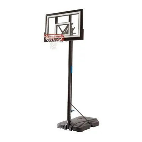
FOOT ADJUST
BASKETBALL SYSTEM
Lifetime basketball systems are designed to be
strong and durable. We strive to make assembly as
easy as possible without compromising quality. If
you get stuck, we have tools to help:
• Watch Our Instructional Videos
Scan the code below to see how it all comes
together.
http://go.lifetime.com/90593playlist
• Prepare the Area
Before you start, decide how you would like to fi ll
your base (sand is recommended, see page 31).
• Recruit Friends and Family
Assembly should take 2 people about 2-3
hours to complete.
TOOLS REQUIRED
3/4"
(2)
(1)
(1)
NEED HELP? TALK TO US!
Call: 1-800-225-3865
7:00 am-5:00 pm (Monday-Friday) MST
and 9:00 am-1:00 pm Saturday MST
®
3/8"
7/16"
(2)
(2)
(1)
(1)
(362 lb)/(163 kg)
(1)
Lifetime's assembly experts offer quick responses and great customer service.
Web: www.lifetime.com/instructions
Live Chat: www.lifetime.com/instructions
9/16"
1/2"
(2)
(2)
3/16"
(2, included)
(1)
(1)
(1)
MODEL# AND PRODUCT ID
Model Number:
90593
TABLE OF CONTENTS
Icon Legend................................2
Notices....................................3
Pole Assembly............................4
Pole to Base Assembly.................8
Backboard to Rim Assembly.......11
Backboard to Pole Assembly......17
Handle Assembly.......................20
Final Assembly..........................29
Maintenance Instructions..........34
Registration...........................34
Warning Sticker........................35
Warranty................................39
(you will need both when contacting us)
Product ID:
Advertisement
Table of Contents

Related Manuals for Lifetime FOOT ADJUST


Summary of Contents for Lifetime FOOT ADJUST
-
Page 1: Table Of Contents
Final Assembly......29 Maintenance Instructions..34 Registration......34 Warning Sticker......35 (362 lb)/(163 kg) Warranty........39 Lifetime’s assembly experts offer quick responses and great customer service. NEED HELP? TALK TO US! MODEL# AND PRODUCT ID (you will need both when contacting us) Call: 1-800-225-3865 Web: www.lifetime.com/instructions... -
Page 2: Icon Legend
CONTACT US • Save this instruction in the event that the manufacturer has to be contacted for replacement parts. Call: 1-800-225-3865 7:00 am–5:00 pm (Monday–Friday) MST and 9:00 am–1:00 pm Saturday MST www.lifetime.com/instructions 1161668 D 1/7/2016... -
Page 3: Notices
WARNINGS & NOTICES WARNINGS & NOTICES / AVERTISSEMENTS ET AVIS / ADVERTENCIAS Y AVISOS SAFETY INSTRUCTIONS FAILURE TO FOLLOW THESE WARNINGS MAY RESULT IN SERIOUS INJURY OR PROPERTY DAMAGE AND WILL VOID WARRANTY. Owner must ensure that all players know and follow these rules for safe operation of the system. To ensure safety, do not attempt to assemble this product without following the instructions carefully. -
Page 4: Pole Assembly
POLE ASSEMBLY HARDWARE REQUIRED Hardware Bag ABH (x2) ABB (x2) ADS (x2) 3/8” x 3 1/2” 3/8” 1/4” x 3/4” ADA (x2) CIH (x2) 1/2” x 2.91 AAF (x2) 3/8” PARTS REQUIRED Metal Parts ” ALH (x1) ALL (x1) Warning Sticker 43”... - Page 5 • If you have trouble with this section, scan the code below to view a video on how to assemble the Pole. • http://go.lifetime.com/footadjustpoleassembly • Align the hole in the bottom of the Top Pole (ALH) with the slot in the top of the Middle Pole (ALF). Secure the Top Pole to the Middle Pole with the hardware shown.
- Page 6 SECTION 1 (CONTINUED) TOOLS AND HARDWARE REQUIRED 9/16" (x2) ABH (x2) ABB (x2) AAF (x2) ADA (x2) ADS (x1) CIH (x1) • Place the Pole Bracket (ALL) onto the 3/8” • Secure the Middle Pole to the Bottom Pole (ALE) using the x 3 1/2”...
- Page 7 SECTION 1 (CONTINUED) TOOLS AND HARDWARE REQUIRED • Strike the end of the Pole Assembly on a piece of scrap wood or cardboard 5–6 times. • Do not strike your feet with the Pole sections, as serious injury may occur. WARNING The Poles must be seated together! Even if the Poles cover the slots before seating, they must be struck on a hard...
-
Page 8: Pole To Base Assembly
POLE TO BASE ASSEMBLY HARDWARE REQUIRED Hardware Bag DSA (x1) 1/4” x 3” BTS (x1) 1/4” ABN (x2) 1/2” x 1/8” AAE (x2) CCL (x2) 5/16” x 1” ABD (x4) AAO (x2) 3/16” 5/16” 5/16” PARTS REQUIRED Metal Part 7” (178mm) ”... - Page 9 ABN (x2) • If you have trouble with this section, scan the code below to view a video on the assembly. • http://go.lifetime.com/footadjustpoletobase • Attach the fl attened end of the Pole Brace (ALI) • Slide the Large Axle (AJC) through the Wheels (AMU) and to the Base (AJM) with the hardware shown.
- Page 10 SECTION 2 (CONTINUED) TOOLS AND HARDWARE REQUIRED 3/16” CCL (x2) DSA (x1) BTS (x1) 1/2" (x2) • Place the Pole assembly on the ground with the Pole Bracket on the Bottom Pole facing up. Position the Large Axle (AJC) under the bottom slots of the Base (AJM) as shown, and step onto the Base so the Axle snaps into the slots. Then rotate the Pole assembly upward so that the Small Axle (AJE) snaps into the upper slots of the Base as shown.
-
Page 11: Backboard To Rim Assembly
BACKBOARD TO RIM ASSEMBLY HARDWARE REQUIRED Hardware Bag AAB (x2) AAJ (x2) AAV (x2) ABK (x4) ABD (x2) ABF (x2) 1/4” 5/16” 5/16” 5/16” 5/16” 7/16” AAS (x2) ABI (x2) ADQ (x2) 1/4” x 2 3/4” 5/16” x 2 1/4” 5/16”... - Page 12 • If you have trouble with this section, scan the code below to view a video on on its assembly. • http://go.lifetime.com/footadjustbackboardtorim • Slide the U-Bolt (AOU) through the Left and Right Backboard Brackets (AJJ & AJK). The U-Bolt must rest in the notches of the...
- Page 13 SECTION 3 (CONTINUED) TOOLS AND HARDWARE REQUIRED AAS (x2) ABS (x2) AAB (x2) • Slide one 1/2” Spacer (ABS) through the Counterbalance Spring (AJY), then fi nger-tighten them to the Backboard Brackets as shown. • Only fi nger-tighten this hardware for now. •...
- Page 14 SECTION 3 (CONTINUED) TOOLS AND HARDWARE REQUIRED 1/2”(x2) ABI (x2) AAJ (x2) ABD (x2) ABF (x2) (x1) AAV (x2) ABK (x2) • Insert two 5/16” x 2 1/4” Tap Bolts (ABI) with the 5/16” Washers (ABD) and the 7/16” Rubber Washers (ABF) through the bottom holes in the back of the Rim (ALX) as shown, and secure the hardware with two 5/16”...
- Page 15 SECTION 3 (CONTINUED) TOOLS AND HARDWARE REQUIRED 1/2”(x2) AJW (x2) ABK (x2) • Slide the Compression Springs (AJW) onto the U-Bolt (AOU), and place the Spring Retainer Plate (AOW) over the Compression Springs. Tighten the 5/16” Nylock Flange Nuts (ABK) until the Rim (ALX) does not wobble to complete this step.
- Page 16 SECTION 3 (CONTINUED) TOOLS AND HARDWARE REQUIRED 1/2”(x2) 3/8”(x1) ADQ (x2) • Bend the Left and Right Backboard Brackets (AJJ & AJK) outward by hand and position the holes in the Backboard Brackets over the holes in the Backboard (AJI). Then securely fasten the Backboard Brackets to the Backboard with the hardware shown.
-
Page 17: Backboard To Pole Assembly
BACKBOARD TO POLE ASSEMBLY HARDWARE REQUIRED Hardware Bag 6 5/8” ADG (x4) ABP (x4) ABL (x4) AAX (x4) 1/2” x 6 5/8” 1/2” x 3/8” .69” x .59” 1/2” PARTS REQUIRED Metal Parts 17” AKC (x2) 22.5” AKB (x2) TOOLS REQUIRED 3/4”... - Page 18 • If you have trouble with this section, scan the code below to view a video on the assembly. • http://go.lifetime.com/footadjusttbackboardtopole • Secure the Short Extension Arms (AKC) and Long Extension Arms (AKB) to the Backboard Brackets in the location shown with the hardware indicated.
- Page 19 SECTION 4 (CONTINUED) TOOLS AND HARDWARE REQUIRED 6 5/8” (x1) 3/4”(x2) ADG (x2) ABP (x4) AAX (x2) • Lay the Backboard and Rim assembly on the ground next to the Pole assembly. Rest the Rim on cardboard to prevent scratching. Then secure the Short and Long Extension Arms (AKC & AKB) to the Pole Assembly with the hardware shown.
-
Page 20: Handle Assembly
HANDLE ASSEMBLY HARDWARE REQUIRED Hardware Bag 6 5/8” ADG (x1) ACZ (x2) 1/2” x 6 5/8” 0.69”x 1.4” AAX (x1) 1/2” 6 1/2 ” ABA (x1) BSJ (x2) AAM (x1) 3/8” x 6 1/2” 1/4” x 1 3/4” 5/16” x 1 1/2” ADT (x4) EKD (x2) EJW (x4) -
Page 21: Parts Identifier
PARTS IDENTIFIER This page intentionally left blank... - Page 22 PARTS IDENTIFIER Metal Part 22.5” ” AKB (x2) ALH (x1) 17” 43” AKC (x2) ALF (x1) AJJ (x1) 43” ALE (x1) AJK (x1) EJT (x1) EKB (x1) EJV (x1) ” (400mm) 7” (178mm) ALI (x2) AJE (x1) AJC (x1) EKC (x1) AOX (x1) EJU (x1) EJY (x1)
- Page 23 PARTS IDENTIFIER Plastic Parts AJI (x1) AMU (x2) AJM (x1) EKL (x1) AKM (x1) AKN (x1) AEF (x2) 1163029 AKP (x1) EJX (x1) AKZ (x1) HARDWARE REQUIRED...
- Page 24 PARTS IDENTIFIER This page intentionally left blank...
- Page 25 • If you have trouble with this section, scan the code below to view a video on the assembly. • http://go.lifetime.com/footadjusthandle • Align the Pedal Bracket (EJY) with the Pedal Support Bracket (EJU), then secure them with the hardware shown.
- Page 26 SECTION 5 (CONTINUED) TOOLS AND HARDWARE REQUIRED EJW (x2) (x1) • Align the assembly to the Outer Tube (EJT), then use a Rubber Mallet to strike them until the holes on the Pedal Support Bracket (EJU) line up with the small pilot holes at the end of the Outer Tube. Use the Self-Tapping Screws (EJW) to secure the Bracket Assembly to the Outer Tube.
- Page 27 SECTION 5 (CONTINUED) TOOLS AND HARDWARE REQUIRED (x1) 3/8”(x2) BZA (x2) CXK (x2) • Press down on the Bracket Assembly on the Outer Tube (EJT), then insert the Inner Channel (EJV) into the Outer Tube. • The multi-notched side of the Inner Channel should face the same direction as the Bracket assembly on the Outer Tube.
- Page 28 SECTION 5 (CONTINUED) TOOLS AND HARDWARE REQUIRED (x1) EKD (x1) EJW (x1) DHK (x1) 7/16”(x2) • Use the measurement of the pole taken in step 1.5 to determine the hardware location for the Lifter Arm Bracket (EKC). Use the following chart to complete the assembly of the next two steps. •...
- Page 29 SECTION 5 (CONTINUED) TOOLS AND HARDWARE REQUIRED (x1) EKD (x1) EJW (x1) DHK (x1) 7/16”(x2) • Insert Lifter Arm Bracket (EKC) to Outer Tube (EJT), then secure them with the hardware shown. • Refer to the chart in step 5.6 for the correct hole location in this step.
- Page 30 SECTION 5 (CONTINUED) TOOLS AND HARDWARE REQUIRED (x1) ADT (x4) • Insert Plug (EKL) into the Lifter Arm (EKB) as shown. 5.10 • Secure the Left and Right Handles (AKM & AKN) to the assembly with the hardware shown. • Handle peices come together at the top to form an arrow shape that will point toward the pole when the assembly is fi...
- Page 31 SECTION 5 (CONTINUED) TOOLS AND HARDWARE REQUIRED 6 5/8” 3/4”(x2) ACZ (x2) ADG (x1) 1/2”(x2) AAX (x1) AAN (x1) AAM (x1) 5.11 • Line up the Handle Assembly as indicated, then secure it with the hardware shown.
- Page 32 SECTION 5 (CONTINUED) TOOLS AND HARDWARE REQUIRED 9/16”(x2) 6 1/2 ” ABA (x1) ABB (x1) 5.12 • Insert the 3/8” x 6 1/2” Hex Bolt (ABA) through the holes in the Short Extension Arms (AKC) that are closest to the Pole. Secure it to the Short Extension Arms with the 3/8”...
-
Page 33: Final Assembly
FINAL ASSEMBLY HARDWARE REQUIRED PARTS REQUIRED Plastic Parts 1163358 AEF (x2) AKP (x1) AKZ (x1) TOOLS REQUIRED 362 lb (163 kg) - Page 34 SECTION 6 (CONTINUED) TOOLS AND HARDWARE REQUIRED • If you have trouble with this section, scan the QR code below to view the assembly video. • http://go.lifetime.com/fi llingthebase • Attach the Net (AKZ). • Remove the plastic fi lm from the backboard.
- Page 35 SECTION 6 (CONTINUED) TOOLS AND HARDWARE REQUIRED 310 lb (141 kg) Two adults are required to complete this part of the assembly. To prevent serious injuries, the Pole should be held down by one adult at all times while the Base is being fi lled. 6.3A •...
- Page 36 SECTION 6 (CONTINUED) TOOLS AND HARDWARE REQUIRED • To adjust the height of the system, hold the handle while depressing the Foot Pedal. Move the handle up or down to the desired height, then release the Foot Pedal to secure the position. •...
- Page 37 SECTION 6 (CONTINUED) TOOLS AND HARDWARE REQUIRED • In order to move the system, please to adjust the system to its lowest position, then move it as shown. WARNING: The system must only be moved by people capable of handling its weight. Do not allow children to move the system.
-
Page 38: Registration
. And you can rest assured that Lifetime will not sell or provide your personal data to other third parties, or allow them to use your personal data for their own purposes. We invite you to read our privacy policy at www.lifetime.com REGISTER today! -
Page 39: Warning Sticker
fils électriques. mécanisme a été conçu uniquement pour soutenir le poids du panneau et de sous peine d’endommager l’équipement et d’annuler la garantie. www.lifetime.com #FS16400 10/12/2004... - Page 40 NOTES / REMARQUES / NOTAS 36 36...
- Page 41 NOTES / REMARQUES / NOTAS...
- Page 42 NOTES / REMARQUES / NOTAS...
- Page 43 2. This warranty is nontransferable and is expressly limited to the repair or replacement of defective product. If the product is defective within the terms of this warranty, Lifetime Products, Inc. will repair or replace defective parts at no cost to the purchaser.
- Page 44 ® AMÉLIOREZ VOTRE ACHAT LIFETIME EN AJOUTANT DES ACCESSOIRES OU DES AUTRES PRODUITS ® Pour acheter des accessoires ou des autres produits Lifetime , rendez-vous une visite à : www.lifetime.com Ou appelez-nous au 1-800-424-3865 Du lundi au vendredi 7 h – 17 h (HNR) et samedi 9 h – 13 h (HNR) ®...
Need help?
Do you have a question about the FOOT ADJUST and is the answer not in the manual?
Questions and answers