MacDon Draper D65 Installation Instructions Manual
Slow speed transport c1997 and c1998
Hide thumbs
Also See for Draper D65:
- Operator's manual (310 pages) ,
- Assembly instruction manual (110 pages) ,
- Assembly instructions manual (44 pages)

Related Manuals for MacDon Draper D65


Summary of Contents for MacDon Draper D65
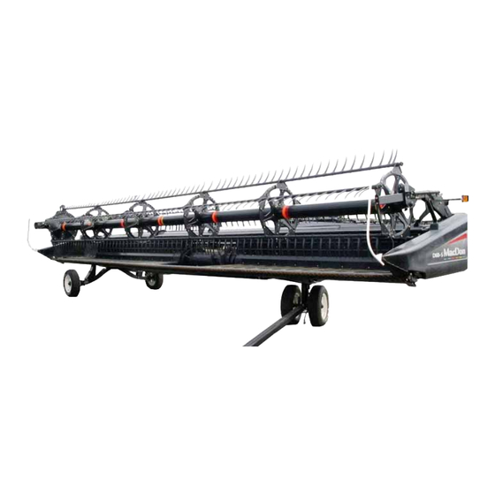
- Page 1 D65 and FD75 ® ® Draper and FlexDraper Headers Slow Speed Transport (C1997 and C1998) Installation Instructions (2016 and Earlier) 169784 Revision H Original Instruction The Harvesting Specialists.
- Page 2 © 2020 MacDon Industries, Ltd. The information in this publication is based on the information available and in effect at the time of printing. MacDon Industries, Ltd. makes no representation or warranty of any kind, whether expressed or implied, with respect to the...
- Page 3 Introduction The Slow Speed Transport option allows you to tow a 9.1–13.7 m (30–45 ft.) MacDon D65 Draper or FD75 FlexDraper® Header behind an agricultural tractor, agricultural combine, or a properly configured MacDon windrower. Do NOT tow with any highway-capable vehicle.
- Page 4 Summary of Changes At MacDon, we’re continuously making improvements, and occasionally these improvements affect product documentation. The following list provides an account of major changes from the previous version of this document. Section Internal Use Only Summary of Change –...
-
Page 5: Table Of Contents
TABLE OF CONTENTS Introduction ..............................i Summary of Changes............................ ii Chapter 1: Safety ............................1 1.1 Signal Words ............................1 1.2 General Safety ............................2 Chapter 2: Parts List............................ 5 2.1 Electrical Parts ............................6 2.2 Tow-Bar ..............................8 2.3 Wheels and Supports ..........................10 Chapter 3: Installation Instructions ...................... - Page 6 TABLE OF CONTENTS 3.12.6 Connecting Harness on European Headers (without Module) ............. 50 3.12.7 Electrical Schematics........................51 Electrical Schematics – European (without Module, with Splice) ............51 Electrical Schematics – Non-European (with Module)................ 52 3.13 Attaching Decals ..........................53 3.14 Installing Slow Moving Vehicle (SMV) Sign....................54 3.15 Installing Divider Rod Storage Bracket ....................
-
Page 7: Chapter 1: Safety
Chapter 1: Safety 1.1 Signal Words Three signal words, DANGER, WARNING, and CAUTION, are used to alert you to hazardous situations. Two signal words, IMPORTANT and NOTE, identify non-safety related information. Signal words are selected using the following guidelines: DANGER Indicates an imminently hazardous situation that, if not avoided, will result in death or serious injury. -
Page 8: General Safety
SAFETY 1.2 General Safety CAUTION The following general farm safety precautions should be part of your operating procedure for all types of machinery. Protect yourself when assembling, operating, and servicing machinery, wear all protective clothing and personal safety devices that could be necessary for the job at hand. Do NOT take chances. - Page 9 SAFETY • Wear close-fitting clothing and cover long hair. NEVER wear dangling items such as scarves or bracelets. • Keep all shields in place. NEVER alter or remove safety equipment. Make sure driveline guards can rotate independently of shaft and can telescope freely. •...
-
Page 11: Chapter 2: Parts List
Chapter 2: Parts List The following parts are included in this kit: 169784 Revision H... -
Page 12: Electrical Parts
PARTS LIST 2.1 Electrical Parts The electrical parts included in the kit will vary slightly depending on whether you have the North American, Australian, and Commonwealth of Independent States (CIS) kit (C1997) or the European kit (C1998). 169784 Revision H... - Page 13 PARTS LIST Figure 2.1: Slow Speed Transport – Electrical Parts Quantity North Part America & Number Description Australia Europe ASSY – LH REAR TRANSPORT LIGHT N.A. & AUS ASSY – LH REAR TRANSPORT LIGHT EUROPE COVER – TRANSPORT LIGHTING 125379 ASSY –...
-
Page 14: Tow-Bar
PARTS LIST 2.2 Tow-Bar Figure 2.2: Slow Speed Transport – Tow-Bar 169784 Revision H... - Page 15 PARTS LIST Part Number Description Quantity HITCH ASSEMBLY – 2 PIECE HEADER END HITCH ASSEMBLY – 2 PIECE TOW END ASSEMBLY – L-PIN 144415 118137 RING ASSEMBLY – HITCH CRADLE (includes 6, 8, 9, 11, A, F, and H) PLATE – LATCH HANDLE 193183 PLATE –...
-
Page 16: Wheels And Supports
PARTS LIST 2.3 Wheels and Supports Figure 2.3: Slow Speed Transport – Wheels and Supports 169784 Revision H... - Page 17 PARTS LIST Part Number Description Quantity ASSY – WHEEL & TIRE COMPLETE 193026 ASSY – LH TRANSPORT SUB ASSY – LH STABILIZER WHEEL SUSPENSION SUB ASSY – RH STABILIZER WHEEL SUSPENSION AXLE SUB-ASSY TRANSPORT LH PIVOT – ASSY 144745 SUB ASSEMBLY – RH SWING AXLE FTG –...
- Page 18 PARTS LIST 169784 Revision H...
- Page 19 PARTS LIST Part Number Description Quantity WASHER – FLAT 4761 BOLT – RHSN 3/8 NC X 1.75 LG GR 5 ZP 50197 BOLT – RHSN 5/8 NC X 1.5 GR 5 ZP 18523 NUT – HEX 1/2 - 13 UNC GR 5 ZP 18591 NUT –...
-
Page 21: Chapter 3: Installation Instructions
Chapter 3: Installation Instructions To install the Slow Speed Transport option, follow all applicable procedures in order. Some procedures don’t apply to all header models. Before installing the Slow Speed Transport option, follow these steps: 1. Use a lifting vehicle to raise header, or attach header to windrower or combine and raise header fully. DANGER To avoid bodily injury or death from unexpected startup or fall of raised header, stop engine, remove key, and engage header lift cylinder stops before going under header for any reason. - Page 22 INSTALLATION INSTRUCTIONS 2. Apply grease to plastic bushings (A), and then install in each side of leg from inside. NOTE: If bushings are hard to install, remove corrosion inhibitor with petroleum-based solvent. Figure 3.2: Left Header Leg 3. Position front axle assembly (A) (MD #193003) inside header leg and install L-pin (B) (MD #144415) to hold axle in place.
- Page 23 INSTALLATION INSTRUCTIONS 7. Locate bar-nut (A) inside pivot pin and install a 5/8 NC x 1 3/8 in. shoulder bolt (B) (MD #48050). Ensure bar-nut (A) is oriented with nut protruding to side shown. Tighten bolt (B). NOTE: Tension link shown in illustration has not yet been installed at this point in the procedure.
- Page 24 INSTALLATION INSTRUCTIONS 10. Adjust spring length (A) to 470 mm (18 1/2 in.) with adjusting nut (B). Figure 3.8: Spring Length The axle is now in transport position. Figure 3.9: Front Axle in Transport Position 169784 Revision H...
-
Page 25: Installing Header Electrical Harness
INSTALLATION INSTRUCTIONS 3.2 Installing Header Electrical Harness To install the header electrical harness, follow these steps: 1. At the inside top of the left header leg, remove cap on connector (A) and cut cable tie (B). Figure 3.10: Left Header Leg 2. - Page 26 INSTALLATION INSTRUCTIONS 4. Secure the wiring harness to the axle with holder (A) and two 3/8 x 5/8 in. self-tapping screws (B). If necessary, loosen clamp inside leg and adjust harness length as required. NOTE: Install and remove self-tapping screws before attaching holder.
-
Page 27: Tow-Bar Cradles
INSTALLATION INSTRUCTIONS 3.3 Tow-Bar Cradles Different cradle assemblies have been designed for different header sizes and applications. Refer to the appropriate section for your header to assemble the left and right cradles. Left Tow-Bar Cradles: • ® Assembling Left Tow-Bar Cradle for a 9.1 Meter (30 Foot) Windrower Header, a 9.1 Meter (30 Foot) FlexDraper Header, or a 10.7 Meter (35 Foot) Rigid Header, page 21 •... -
Page 28: Assembling Left Tow-Bar Cradle For A 9.1 Meter (30 Foot) Rigid Combine Header
INSTALLATION INSTRUCTIONS Assembling Left Tow-Bar Cradle for a 9.1 Meter (30 Foot) Rigid Combine Header 1. Retrieve hitch cradle assembly (A), extension plate (B) (MD #193122), and frame leg support (C) (MD #193115) from kit. 2. Assemble parts as shown with four 3/8 NC x 1 in. carriage bolts (D) (MD #135623) and flanged smooth face lock nuts (MD #135248). -
Page 29: Right Tow-Bar Cradles
INSTALLATION INSTRUCTIONS 3.3.2 Right Tow-Bar Cradles Assembling Right Tow-Bar Cradle for a 9.1 Meter (30 Foot) D65 Windrower Header 1. Retrieve hitch cradle assembly (A) (MD #193148) from kit. No assembly is required. Figure 3.17: Right Cradle Assembly Assembling Right Tow-Bar Cradle for a 9.1 Meter (30 Foot) Rigid Combine Header 1. -
Page 30: Assembling Right Tow-Bar Cradle For A 10.7-13.7 Meter (35-45 Foot) Header
INSTALLATION INSTRUCTIONS Assembling Right Tow-Bar Cradle for a 10.7–13.7 Meter (35–45 Foot) Header 1. Retrieve hitch cradle assembly (A) and frame leg support (B) (MD #193115) from kit. 2. Assemble parts as shown with two 3/8 NC X 1 in. carriage bolts (C) (MD #135623) and flanged smooth face lock nuts (MD #135248). -
Page 31: Installing Front Suspension And Left Tow-Bar Cradle
INSTALLATION INSTRUCTIONS 3.4 Installing Front Suspension and Left Tow-Bar Cradle 1. Loosely install four 3/8 NC x 1 in. carriage bolts (A) (MD #100456) at the base of the vertical leg. Install bolts from inside leg. Figure 3.21: Left Header Leg 2. - Page 32 INSTALLATION INSTRUCTIONS 5. Position left tow-bar cradle assembly (A) on bolts (B). 6. Fasten channel/spring assembly and tow-bar cradle in place at location (B) with flanged smooth-faced lock nuts (MD #30228). 7. Finish attaching cradle assembly using one 1/2 NC x 1 in. ®...
-
Page 33: Rear Suspension And Right Side Tow-Bar Cradle
INSTALLATION INSTRUCTIONS 3.5 Rear Suspension and Right Side Tow-Bar Cradle The procedure for installing the rear suspension and the right side tow-bar cradle varies depending on the header type and width. See the appropriate procedure below: • 3.5.1 Installing Rear Suspension and Right Tow-Bar Cradle on a 9.1 Meter (30 Foot) D65 Windrower Header, page 27 •... - Page 34 INSTALLATION INSTRUCTIONS 7. Install cradle assembly (A) onto back-tube channel as shown using three 3/8 NC x 5/8 in. hex washer head self- tapping bolts (B) (MD #101898). Figure 3.28: Right Cradle Assembly 8. Pull handle (A) to release the spring and position linkage in fourth slot (B) from the top.
-
Page 35: Installing Rear Suspension And Right Side Tow-Bar Cradle On All Headers Except The 9.1 Meter (30 Foot) D65 Windrower Header
INSTALLATION INSTRUCTIONS 9. Remove L-pin (A) from leg storage location and install in transport lock position. The right fixed axle is now in transport position. Figure 3.30: Right Header Leg 3.5.2 Installing Rear Suspension and Right Side Tow-Bar Cradle on All Headers Except the 9.1 Meter (30 Foot) D65 Windrower Header To install the rear suspension and right side tow-bar cradle, follow these steps: 1. - Page 36 INSTALLATION INSTRUCTIONS 2. Lift axle (A) and channel/spring subassembly (B), and position lower end of subassembly (B) into leg. 3. Position lower end of subassembly (B) on bolts (C). 4. Slide subassembly (B) into leg. 5. Fasten subassembly to leg at (C) with four flange nuts (MD #30228).
- Page 37 INSTALLATION INSTRUCTIONS 10. Remove L-pin (A) from leg storage location. Figure 3.35: Right Header Leg – L-Pin Storage Location 11. Install L-pin (A) in transport lock position. The right fixed axle is now in transport position. Figure 3.36: Right Header Leg – L-Pin Transport Location 169784 Revision H...
-
Page 38: Installing Rear Fixed Axle
INSTALLATION INSTRUCTIONS 3.6 Installing Rear Fixed Axle 1. Remove skid shoe if needed. Refer to the header operator’s manual for procedure. 2. Position a 2 x 4 wooden block (A) or equivalent between the right leg and draper to allow installation of the support assembly. - Page 39 INSTALLATION INSTRUCTIONS 6. Position fixed axle assembly (A) in leg and align mounting hole in axle with aft hole (B) in leg. 1011613 Figure 3.40: Fixed Axle Assembly 7. Position pivot casting assembly (A) onto leg. Figure 3.41: Right Leg 169784 Revision H...
- Page 40 INSTALLATION INSTRUCTIONS 8. Install two 21/32 in. I.D. flat washers (A) (MD #18600) under bolt head (B) and install through leg and pivot casting assembly (C). Figure 3.42: Rear Fixed Axle 9. Install four 21/32 in. I.D. flat washers (A) (MD #18600) and smooth-faced lock nut (C) (MD #135341) on threaded end of bolt (B).
- Page 41 INSTALLATION INSTRUCTIONS IMPORTANT: To prevent equipment failure, tighten bolts to the specified torque values. 13. Tighten carriage bolt (A) and torque to 203 Nm (150 lbf·ft). 14. Tighten the remaining three carriage bolts (B), (C), and (D), and torque to 203 Nm (150 lbf·ft). NOTE: ONLY bolts (B), (C), and (D) can be torqued in any order.
-
Page 42: Installing Rear Swing Axle
INSTALLATION INSTRUCTIONS 3.7 Installing Rear Swing Axle 1. Remove 5/8 NC x 4 1/2 in. bolt (A) from axle support swivel (B). Ensure spacer (C) remains in place. Make note of hardware orientation for replacement in the next step. Figure 3.48: Rear Swing Axle IMPORTANT: To prevent equipment failure, tighten bolts to the specified torque values. - Page 43 INSTALLATION INSTRUCTIONS 5. Adjust gap (A) between cutterbar and axle support (B) to 0.5–4.0 mm (1/64–5/32 in.) by loosening jam nut (C) and turning adjuster bolt (D). Tighten jam nut into adjuster bolt to lock. Figure 3.51: Rear Swing Axle 169784 Revision H...
-
Page 44: Checking Axle Hub Pivot
INSTALLATION INSTRUCTIONS 3.8 Checking Axle Hub Pivot Perform the following check to ensure that the wheel hub pivot is snug while in the transport position. 1. Check that hub pivot (A) is in transport position and ensure that L-pin (B) has locked the hub. 2. -
Page 45: Checking Latch Alignment
INSTALLATION INSTRUCTIONS 3.9 Checking Latch Alignment To check the axle latch alignment, follow these steps: 1. Move the swing axle (A) to field position. 2. Check alignment of latching system. Swing axle (A) should freely engage latch (B) on fixed axle (C). If it does, skip the remaining steps. - Page 46 INSTALLATION INSTRUCTIONS NOTE: It may be necessary to add washers (B) (not supplied) between plates at top or bottom bolts (A) on one of the axles to achieve proper plate alignment for latching. Some light grinding may also be necessary. 6.
-
Page 47: Installing Wheels
INSTALLATION INSTRUCTIONS 3.10 Installing Wheels To install the wheels, follow these steps: 1. Attach the four wheels to hubs with bolts provided in hubs. 2. Torque wheel bolts to 110–120 Nm (80–90·lbf·ft). Refer to bolt tightening sequence illustration at right. 3. -
Page 48: Adjusting Axle Brace
INSTALLATION INSTRUCTIONS 3.11 Adjusting Axle Brace To adjust the axle brace, follow these steps: 1. Loosen bolts (A) on latch brace (B). 2. Attach latch mechanism (C) to cutterbar. 3. Adjust latch mechanism parallel to attachment plate (D) and tighten hardware. NOTE: Keeping latch mechanism parallel with plate will provide easy attachment and detachment. -
Page 49: Lights
INSTALLATION INSTRUCTIONS 3.12 Lights Procedures for installing and connecting lights and electrical harnesses vary depending on the location of sale. Refer to the appropriate procedures for your unit. 3.12.1 Installing Endshield Light To install the endshield light, follow these steps: 1. -
Page 50: Installing Reel Arm Light
INSTALLATION INSTRUCTIONS 7. Reinstall bracket (A) on lighting cover (B) with existing hardware (C). Figure 3.64: Light Cover 8. Position light assembly (A) on endsheet, picking up existing holes, and install three 3/8 NC x 3/4 in. carriage bolts (B) (MD #21472) and flange nuts (MD #30228). -
Page 51: Installing Light Wiring Harness
INSTALLATION INSTRUCTIONS 3. Install light assembly (A) inside reel right support arm with two 1/2 NC x 1-1/2 in. hex bolts (B) (MD #18723) and smooth face lock nuts (MD #50186). Tighten bolts. Figure 3.67: Light Installed on Reel Arm 3.12.3 Installing Light Wiring Harness To install the light wiring harness, follow these steps: 1. -
Page 52: Installing Splice
INSTALLATION INSTRUCTIONS 4. Route harness (A) to forward end of arm and make connection (B) at light. 5. Secure harness (A) to inside of reel arm with two clamps (C) (MD #135233), 3/8 NC x 3/4 in. carriage bolts (MD #21863), and smooth face lock nuts (MD #30228). - Page 53 INSTALLATION INSTRUCTIONS 2. Unclip and pull back the terminal position assurance (TPA) clip (B) on connector (A). Figure 3.73: Connector 3. Locate the wire (A) inside the conduit from pin position A on connector. 4. Pull out a short length to accommodate the splice. Figure 3.74: Connector 5.
- Page 54 INSTALLATION INSTRUCTIONS 7. Pull out the green weather plug (B) from position (F) on connector (A). Figure 3.76: Connector 8. Insert splice (B) at position (F). 9. Connect other end of splice to wire from pin position (A) with a T-type connector, or by soldering the splice to the existing wire.
-
Page 55: Connecting Harness On Non-European Headers (With Module)
INSTALLATION INSTRUCTIONS 3.12.5 Connecting Harness on Non-European Headers (with Module) This topic is for D65 and FD75 headers sold outside of Europe. For instructions on connecting the lighting harness on European headers, refer to 3.12.6 Connecting Harness on European Headers (without Module), page 1. -
Page 56: Connecting Harness On European Headers (Without Module)
INSTALLATION INSTRUCTIONS 3.12.6 Connecting Harness on European Headers (without Module) This topic is for D65 and FD75 headers sold in Europe. For instructions on connecting the lighting harness on other headers with lighting module, refer to 3.12.5 Connecting Harness on Non-European Headers (with Module), page 1. -
Page 57: Electrical Schematics
INSTALLATION INSTRUCTIONS 3.12.7 Electrical Schematics Electrical Schematics – European (without Module, with Splice) Figure 3.81: Electrical Schematic (European) A - Hitch Section – Tow End B - Hitch Section – Header End C - Header Section D - Endsheet Section E - Lamp at Reel Arm F - Lamp at Header Tube G - See Enlargement H... -
Page 58: Electrical Schematics - Non-European (With Module)
INSTALLATION INSTRUCTIONS Electrical Schematics – Non-European (with Module) These schematics are for headers sold outside of Europe. Figure 3.82: Electrical Schematic (Non-European) A - Hitch Section – Tow End B - Hitch Section – Header End C - Header Section D - Module E - Endsheet Section F - Lamp at Reel Arm... -
Page 59: Attaching Decals
INSTALLATION INSTRUCTIONS 3.13 Attaching Decals 1. Clean off mounting surface and install decals at locations shown in the illustrations below: Figure 3.83: Decal Locations Figure 3.84: Decal Locations 169784 Revision H... -
Page 60: Installing Slow Moving Vehicle (Smv) Sign
INSTALLATION INSTRUCTIONS 3.14 Installing Slow Moving Vehicle (SMV) Sign To install the SMV sign, follow these steps: 1. Remove existing bolt (A) in hose support at right end reel arm. Figure 3.85: Reel Arm 2. Assemble SMV sign (A) and bracket (B) with a 3/8 NC x 3/4 in. -
Page 61: Installing Divider Rod Storage Bracket
INSTALLATION INSTRUCTIONS 3.15 Installing Divider Rod Storage Bracket To install the divider rod storage bracket, follow these steps: 1. Retrieve divider rod storage bracket from kit. 2. Position bracket (B) on right endsheet brace as shown and install 3/8 NC x 3/4 in. carriage bolt (A) and smooth face lock nut. -
Page 62: Tow-Bar Brackets
INSTALLATION INSTRUCTIONS 3.16 Tow-Bar Brackets The tow-bar is stored on the header just behind the backtube. It is secured to each endsheet with a bracket and to the backtube with two cradles. The 9.1 m (30 ft.) D65 Draper Header uses a different bracket on the right endsheet from other models. Both bracket types are included in the kit. - Page 63 INSTALLATION INSTRUCTIONS 2. Line up the pilot hole drilling template as shown at right. The bottom right hole in the template should line up with the hole where the wiring harness clip bolt was located (A). b. The upper left hole in the template should line up with the existing hole (B) on the fore side of the clip bolt hole.
-
Page 64: Installing Bracket On Right Endsheet - Headers Except The 9.1 Meter (30 Foot) D65 Headers
INSTALLATION INSTRUCTIONS 3.16.3 Installing Bracket on Right Endsheet – Headers Except the 9.1 Meter (30 Foot) D65 Headers This procedure only applies to headers other than the 9.1 m (30 ft.) D65. For instructions on installing the tow-bar bracket 3.16.2 Installing Bracket on Right Endsheet – 9.1 Meter (30 Foot) D65 on the right endsheet of the 9.1 m (30 ft.), refer to Headers, page 1. -
Page 65: Attaching Tow-Bar
INSTALLATION INSTRUCTIONS 3.17 Attaching Tow-Bar Figure 3.95: Tow-Bar Sections A - Tow Vehicle B - Header C - Towing Vehicle Section D - Header Section E - Outer End of Tow Vehicle Section F - Inner End of Tow Vehicle Section G - Inner End of Header Section H - Outer End of Header Section 169784... - Page 66 INSTALLATION INSTRUCTIONS The tow-bar consists of two sections which make storage and handling easier. Attach tow-bar to header as follows: 1. Position outer end (A) of header section onto front wheel hook (B). 2. Push down until latch (C) captures the end (A). 3.
- Page 67 INSTALLATION INSTRUCTIONS 7. Fully insert L-pin (A) in upper hole and turn pin to lock it. Secure with ring pin (B). Figure 3.99: Tow-Bar Inner Ends Attached Together 8. Connect hitch harness to header electrical connector (A) at front wheel. Figure 3.100: Electrical Connection at Front Wheel 9.
- Page 68 INSTALLATION INSTRUCTIONS 10. Attach hitch pin clevis/pintle (A) to outer end (B) of towing vehicle section using two 5/8 NC X 4 in. bolts (C) and flange lock nuts (D). 11. Tighten hardware. Figure 3.102: Tow Vehicle Outer End Pintle Setup Figure 3.103: Tow Vehicle Outer End Clevis Setup 169784 Revision H...
-
Page 69: Detaching And Storing Tow-Bar
INSTALLATION INSTRUCTIONS 3.18 Detaching and Storing Tow-Bar To detach and store the tow-bar, follow these steps: 1. Disconnect wiring connector (A) at front wheel. Figure 3.104: Electrical Connection at Front Wheel 2. Remove clevis pin (A). 3. Push latch (B) and lift tow-bar (C) from hook. Release latch (B) and replace clevis pin (A). - Page 70 INSTALLATION INSTRUCTIONS 6. Position outer end of towing vehicle section (A) in bracket (B) on left endsheet and install hitch pin (C). Secure with lynch pin. 7. Position inner end of towing vehicle section in cradle (D), and secure with bungee (E). Figure 3.107: Towing Vehicle Section of Tow-Bar 8.
-
Page 71: Conversion To And From Transport
INSTALLATION INSTRUCTIONS 3.19 Conversion to and from Transport Refer to your header operator’s manual for procedures to convert into and out of transport mode. 169784 Revision H... - Page 74 MacDon Industries Ltd. MacDon Brasil Agribusiness Ltda. 680 Moray Street Rua Grã Nicco, 113, sala 404, B. 04 Winnipeg, Manitoba Mossunguê, Curitiba, Paraná Canada R3J 3S3 CEP 81200-200 Brasil t. (204) 885-5590 f. (204) 832-7749 t. +55 (41) 2101-1713 f. +55 (41) 2101-1699 MacDon, Inc.
Need help?
Do you have a question about the Draper D65 and is the answer not in the manual?
Questions and answers