Table of Contents
Advertisement
Advertisement
Table of Contents
Troubleshooting

Related Manuals for Raymarine iTC-5


Summary of Contents for Raymarine iTC-5
- Page 1 Ins ta lla tion ins tructions Docume nt numbe r: 87138-3 Da te : 03-2012...
- Page 3 Product handbooks The latest versions of all English and translated handbooks are available to download in PDF format from the website www.raymarine.com. Please check the website to ensure you have the latest handbooks.
-
Page 5: Table Of Contents
Safety notices..............7 Chapter 6 Options and accessories ....... 37 Chapter 2 Planning the installation ......9 6.1 Spares ..............38 2.1 About the iTC-5 Converter ......... 10 6.2 SeaTalk cables and accessories ......38 2.2 Handbook information ..........11 2.3 System examples............ - Page 6 iTC-5...
-
Page 7: Chapter 1 Important Information
Warning: Exposed wires Declaration of conformity With the cover open the exposed transducer wires Raymarine Ltd. declares that this product is compliant with the provide a potential for electric shock. essential requirements of EMC directive 2004/108/EC. The original Declaration of Conformity certificate may be viewed on Warning: Potential ignition source the relevant product page at www.raymarine.com. - Page 8 Directive requires the recycling of waste electrical and electronic equipment. Whilst the WEEE Directive does not apply to some Raymarine products, we support its policy and ask you to be aware of how to dispose of this product. Technical accuracy To the best of our knowledge, the information in this document was correct at the time it was produced.
-
Page 9: Chapter 2 Planning The Installation
Chapter 2: Planning the installation Chapter contents • 2.1 About the iTC-5 Converter on page 10 • 2.2 Handbook information on page 11 • 2.3 System examples on page 11 • 2.4 Pack contents on page 15 • 2.5 Tools required on page 16... -
Page 10: About The Itc-5 Converter
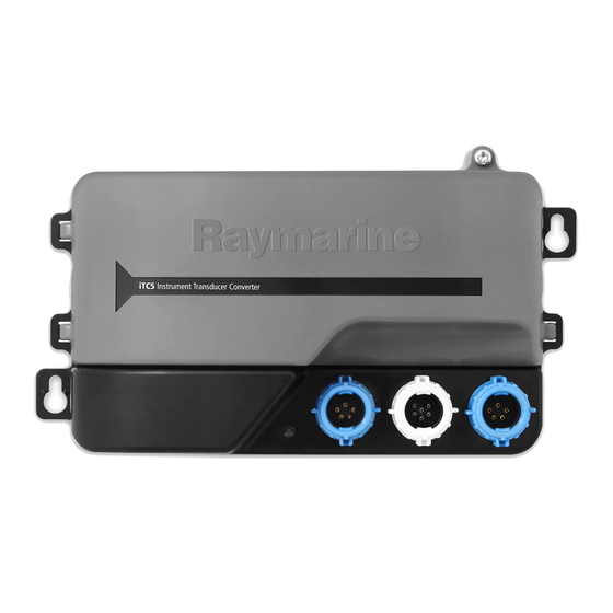
2.1 About the iTC-5 Converter • AWA — Apparent wind angle • AWS — Apparent wind speed The iTC-5 converter allows connection of a range of compatible analogue transducers directly to the SeaTalk network. • Depth • STW — Speed through water •... -
Page 11: Handbook Information
2.2 Handbook information 2.3 System examples This handbook describes how to include the iTC-5 converter within The iTC-5 converter can be connected into a SeaTalk network, a SeaTalk network, and connect compatible transducers. compatible transducers can then be connected directly to the converter. - Page 12 Item Description ST70 Instrument display. 2 x i70 Instrument displays. Terminated SeaTalk T-piece connector Terminated iTC-5 Rudder reference transducer Depth transducer Fluxgate compass Raymarine wind transducer or rotavecta Speed and sea temperature transducer iTC-5...
- Page 13 Extended SeaTalk system example AIS 650 Cla s s B Tra ns ce ive r ta tus US B SMART P WR/Da ta GP S ANT VHF ANT S e a Ta lk 12 V S e a Ta lk D12131-1 Planning the installation...
- Page 14 5–way connector Depth transducer Speed and sea temperature transducer Raymarine wind transducer or rotavecta Note: In a SPX autopilot system the fluxgate compass and rudder reference transducer must be connected directly to the course computer and not via the iTC-5. iTC-5...
-
Page 15: Pack Contents
2.4 Pack contents Seatalk SeaTalk (Next Generation) is an enhanced protocol for connection The iTC-5 converter pack comes with the following items: of compatible marine instruments and equipment. It replaces the older SeaTalk and SeaTalk protocols. SeaTalk utilizes a single backbone to which compatible instruments connect using a spur. -
Page 16: Tools Required
2.5 Tools required Tools required for installation D12087-1 Item Description Power Drill Pozidrive screwdriver 3.2 mm (1/8”) drill bit iTC-5... -
Page 17: Chapter 3 Cables And Connections
Chapter 3: Cables and connections Chapter contents • 3.1 General cabling guidance on page 18 • 3.2 Converter connections on page 19 Cables and connections... -
Page 18: General Cabling Guidance
• Unless otherwise stated use only standard cables of the correct • antennae. type, supplied by Raymarine. • Ensure that any non-Raymarine cables are of the correct quality Strain relief and gauge. For example, longer power cable runs may require larger wire gauges to minimize voltage drop along the run. -
Page 19: Converter Connections
3.2 Converter connections SeaTalk connections The iTC-5 converter has 2 x backbone connectors and 1 x spur The converter connects in line as part of the SeaTalk backbone. It connector. provides connections to enable transducers to be installed onto the SeaTalk network. - Page 20 3. Fully insert the cable connector. 4. Rotate locking collar clockwise (2 clicks) until it snaps into the LOCKED position. Transducer connections The iTC-5 allows connection of 5 transducers onto your SeaTalk network. Speed and sea temperature transducer connections WIND...
- Page 21 Rotavecta connections Item Cable color Signal name White Temperature (signal) Brown Temperature 0V Wind connections ROTA COMPASS DEPTH RUDDER ROTA D12038-1 COMPASS Item Cable color Signal name Rotor + DEPTH RUDDER Blue Rotor – D12037-1 Fluxgate compass connections Item Cable color Signal name Wind V+ Screen...
- Page 22 Blue Piezoceramic + WIND ROTA V ANE Black Piezoceramic – COMPASS Warning: iTC-5 High voltage DEPTH RUDDER Do not touch exposed transducer wires whilst the converter is powered on and the cover is open. D12040-1 Item Cable color Signal name...
- Page 23 6. Ensure spade terminals are fully pushed home and that terminals do not touch. 7. Secure cables into their runs. 8. Close the cover and retighten the cover retention screw. 9. Switch on the power supply. Transducer cable lengths The table below shows the cable lengths supplied with transducers. Transducer Cable length Speed and sea temperature...
- Page 24 iTC-5...
-
Page 25: Chapter 4 Location And Mounting
Chapter 4: Location and mounting Chapter contents • 4.1 Unit dimensions on page 26 • 4.2 Mounting on page 26 • 4.3 Removing the front cover on page 28 Location and mounting... -
Page 26: Unit Dimensions
4.1 Unit dimensions 4.2 Mounting iTC-5 Dimensions The converter is designed to be surface mounted. Before mounting the converter ensure that you have: • Selected a suitable location where the converter is: – Reasonably well protected from physical damage. – maintained in a dry condition, where there is no likelihood of the converter being splashed. - Page 27 10. Replace converter cover, ensuring that the transducer cables are placed into the relevant cable guides as shown below 11. Switch on power supply and check system. Transducer cable guides D12308-1 Item Description Speed and sea temperature transducer cable guide. D12041-1 Wind transducer / Rotavecta cable 1.
-
Page 28: Removing The
2. Push in the cover clip located on the right hand side. 3. Pull the right hand side of the cover away from the unit slightly. 4. Pull the left hand side of the cover away from the unit. Cover replacement is a reversal of cover removal. iTC-5... -
Page 29: Chapter 5: System Checks And Troubleshooting
5.1 Serial number location on page 30 • 5.2 Typical system checks on page 30 • 5.3 iTC-5 LED Status indicators on page 31 • 5.4 System data troubleshooting on page 33 • 5.5 Raymarine customer support on page 34 •... -
Page 30: Serial Number Location
Note: On autopilot systems the rudder reference and fluxgate compass should be connected directly to the course computer. All checks should be performed in a safe and familiar environment and in accordance with the instructions supplied with each product. iTC-5... -
Page 31: Itc-5 Led Status Indicators
5.3 iTC-5 LED Status indicators The LED status indicators show the status of the connected transducers and the SeaTalk network. The converter has 6 LED status indicators: ROTA V ANE D12133-1 Item LED Indicator Speed and sea temperature transducer Wind transducer or rotavecta... - Page 32 LED indications The sequence of the LED provides the user with an indication of the status of connected transducers and the connection to the SeaTalk network. LED indicator LED on Slow continuous pulse Rapid continuous pulse Short intermittent pulse...
-
Page 33: System Data Troubleshooting
Network problem Check that all required equipment is connected to the network.. from some but not all displays. Check the status of the Raymarine network Switch. Check that SeaTalk / RayNet cables are free from damage. Software mismatch between equipment Contact Raymarine technical support may prevent communication. -
Page 34: Raymarine Customer Support
Raymarine provides a comprehensive customer support service. Nominal supply voltage 12 V dc You can contact customer support through the Raymarine website, telephone and email. If you are unable to resolve a problem, please Operating voltage range 9 — 16 V dc use any of these facilities to obtain additional help. -
Page 35: Nmea2000 Sentences
5.7 NMEA2000 sentences Protocol PGN name Receive Transmit • NMEA2000 128259 Speed, water The converter supports the following NMEA2000 sentences. referenced Protocol PGN name Receive Transmit • NMEA2000 128267 Depth • NMEA2000 59904 ISO request • NMEA2000 128275 Distance log •... - Page 36 iTC-5...
-
Page 37: Chapter 6 Options And Accessories
Chapter 6: Options and accessories Chapter contents • 6.1 Spares on page 38 • 6.2 SeaTalk cables and accessories on page 38 Options and accessories... -
Page 38: Spares
1 m (3.3 ft) A06039 spur SeaTalk 3 m (9.8 ft) A06040 spur A06041 SeaTalk 5 m (16.4 ft) spur SeaTalk 0.4 m (1.3 ft) A06033 backbone SeaTalk 1 m (3.3 ft) A06034 backbone SeaTalk 3 m (9.8 ft) A06035 backbone iTC-5... - Page 39 Description Part No Notes Description Part No Notes SeaTalk 5 m (16.4 ft) A06036 SeaTalk (3 pin) to A06047 backbone SeaTalk adaptor cable 0.4 m (1.3 ft) SeaTalk 9 m (29.5 ft) A06068 backbone SeaTalk2 (5 pin) to A06048 SeaTalk adaptor cable SeaTalk 20 m (65.6 ft)
- Page 40 iTC-5...
- Page 41 Owner notes:...
- Page 42 Owner notes:...
- Page 44 www.ra ym a rin e .c o m...
Need help?
Do you have a question about the iTC-5 and is the answer not in the manual?
Questions and answers