Table of Contents
Advertisement
HEAT PRESS TECHNOLOGY
Operators Handbook
All products within the ADKINS range are labelled with CE marking and are manufactured and tested to comply with EC safety regulations.
All products within the ADKINS range are labelled with CE marking and are manufactured and tested to comply with EC safety regulations.
Rev C - 04/12/19
Rev C - 04/12/19
©2018 A. Adkins & Sons Ltd. All rights reserved. E&OE. V1.0.
©2018 A. Adkins & Sons Ltd. All rights reserved. E&OE. V1.0.
BETA MAXI
(115 VOLTS)
Advertisement
Table of Contents

Related Manuals for Adkins Beta Maxi


Summary of Contents for Adkins Beta Maxi
- Page 1 Rev C - 04/12/19 All products within the ADKINS range are labelled with CE marking and are manufactured and tested to comply with EC safety regulations. All products within the ADKINS range are labelled with CE marking and are manufactured and tested to comply with EC safety regulations.
- Page 2 Preface Dear User Welcome to the growing group of Beta Maxi (115V) Press users. The product you have purchased has been carefully designed and manufactured to ensure that you, the user, will gain the maximum benefit. All A. Adkins & Sons Limited products are specifically designed to ensure ease of use with particular attention to safety requirements.
-
Page 3: Table Of Contents
Contents Introduction Beta Maxi (115V) Press What did you receive? Specifications of the Beta Maxi (115V) Press Safety Safety tips Installation Transport instructions Installing the machine Wiring the plug for a 115 VAC machine Adjusting the pressure How to operate the Beta Maxi (115V) -
Page 4: Introduction Beta Maxi (115V) Press
It is ideal for medium volume production. The work area of the Beta Maxi (115V) Press is 15 in x 20 in (38 cm x 50 cm), but machines may have, to special order, optional smaller sized interchangeable worktables of any size and various shapes within these table sizes. -
Page 5: What Did You Receive
What did you receive? The Beta Maxi (115V) Press has been placed in a cardboard box and held in place with foam and banded onto a pallet. The following articles should have been delivered: Beta Maxi (115V) Press complete with mains cable and plug Beta Maxi (115V) Press Users’... -
Page 6: Specifications Of The Beta Maxi (115V) Press
It is ideal for medium volume production. The work area of the Beta Maxi (115V) Press is 15 in x 20 in (38 cm x 50 cm), but machines may have, to special order, optional smaller sized interchangeable worktables of any size and various shapes within these table sizes. -
Page 7: Safety
Safety The Beta Maxi (115V) Press has been equipped with various safety features to ensure operator safety. A thermal cut-out on the heating element shuts off the power to the element if the temperature exceeds 500 F ± 27 F (260... - Page 8 These may include air extraction and / or masks for personnel. Please refer to page 13 for an illustration of the Beta Maxi (115V) Press. Page 5...
-
Page 9: Installation
2. Installation Transport instructions The machine comes to you, placed in a cardboard box, and held in place with foam and banded onto a pallet. If you have to transport the machine at any time it is recommended that you use a similar box and packing methods. -
Page 10: Adjusting The Pressure
Adjusting the pressure This press is fitted with a pressure-adjusting unit, which enables the heat plate assembly to be raised or lowered by use of a pressure adjustment knob located on the top of the machine: To increase pressure or to use thinner materials turn knob clockwise. -
Page 11: How To Operate The Beta Maxi (115V)
3.1.2 Turn on the Beta Maxi (115V) Press; the on/off switch is on the left side of the swing head. Ensure that the operating handle is in the up position. Set the machine controls as necessary. -
Page 12: Pressing Pad Assembly
Working with Heat Transfer Materials (cont.) 3.2.5 Start the sequence by pulling the handle release knob to unlock the handle from its vertical position. Pull the handle down to the lock position using both hands on the handle. This will make the micro switch, which starts the timer. When the set time has elapsed, the buzzer sounds. -
Page 13: Hints And Tips
Fault Diagnosis (cont.) CAUTION In all fault conditions switch off the power to the machine and unplug the machine from the electrical supply before contacting your machine supplier. Hints and Tips Transfer Printing Extra care should always be taken to ensure that transfer paper is placed print down onto the article, as mistakes will result in the heat plate becoming soiled with ink and spoiling following work. -
Page 14: Maintenance Of The Machine
Maintenance of the Machine Daily Maintenance For good press results it is important to keep the press surfaces clean. Wipe the surface of the heat plate with a dry non-abrasive cloth before use when the plate is cold. When the heat plate is hot and not in use, keep open position away from the silicone pad. -
Page 15: Machine Drawings, Diagrams And
Machine Drawings, Diagrams and Declarations On the following pages are the schematic diagrams for the Beta Maxi (115V) Press. General Layout …………..……………… Page 13 Control Unit – Operation ……...………... Page 14 Exploded Diagram and Parts List ……… Page 15 Machine (inc. Controller) - Electrical Diagram ……..………………. -
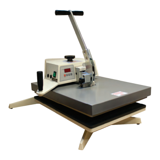
Page 16: General Layout
5.1 General Layout of the Beta Maxi (115V) MACHINE OPERATING HANDLE TIME/TEMP CONTROL UNIT PRESSURE ADJUSTING KNOB ON/OFF SWITCH MACHINE FUSE HEAD SWING AWAY HANDLE HEAT PLATE HANDLE RELEASE KNOB TABLE AND PAD Page 13... -
Page 17: Control Unit Operation
5.2 Operation of Control Unit, Setting Time and Temperature (The head must always be in the up position before the controller is set) Setting Temperature Switch Press; Display 'TEMP' indicator will light up. TEMP TEMP Press 'MODE' button to select 'Set' on indicator. -
Page 18: Exploded Diagram And Parts List
Thermal cut out BM338 Micro switch BMC462 Fab arm BMC18 Thrust bar BMC19/B Adjusting stud and lock ring complete BMC19/C Overlay R/H Adkins fascia BMC630 Mains cable (3183Y) BLK Scalloped handwheel BMC507 Instrument cover BME10 27a 9 V DC Display board BMC655/A... -
Page 19: Machine (Inc. Controller) - Electrical Diagram
5.4 Electrical Diagram green (2.5) Page 16... -
Page 20: Design Change
6. Design Change With the policy of constant improvement and/or modification to meet changing conditions, the right is reserved to change the design and/or specifications at any time without prior notification, and therefore specifications may vary and not be in accordance with this manual. Page 17... -
Page 21: Guarantee
“as is”. A. Adkins & Sons Limited does not warrant that the functions of the press will meet the customer’s requirements or expectations. -
Page 22: Declaration Of Conformity
A. ADKINS & SONS LIMITED DECLARATION OF CONFORMITY Application of Council Directives: Machinery, Low Voltage. E.M.C. Standards to which Conformity is BS EN ISO 12100:2010 - Safety of machinery: Basic Technology, Principles of Design. Declared: BS EN 60204-1:2006+A1:2009 - Safety of machinery: Electrical Equipment of Machines.
Need help?
Do you have a question about the Beta Maxi and is the answer not in the manual?
Questions and answers