Table of Contents
Advertisement
Quick Links
Advertisement
Table of Contents

Related Manuals for Aircotec XC-trainer Series

Summary of Contents for Aircotec XC-trainer Series
- Page 1 Manual V1.00_2009_V5 Page 1...
- Page 2 Manual V1.00_2009_V5 Page 2...
- Page 3 Copying or propagating this handbook, any of the associated software, or parts thereof, is only allowed with written consent from AIRCOTEC. Please note that changes in the name of technical progress may occur.
- Page 4 Should the instrument become flooded with seawater it must be thoroughly rinsed with fresh water before drying. Following this a comprehensive check at AIRCOTEC is then required. You use the XC-Trainer at you own risk. The manufacturer is not liable for damage or loss resulting from the use of the instrument, or the software included in the package.
- Page 5 Protect from salt-water spray, rain and humidity. Should the instrument get wet wipe it dry immediately? In case of water getting inside the instrument we suggest you let us check it for you at AIRCOTEC. Protect the instrument from extreme temperatures. Both extreme highs and lows adversely affect battery performance and lifespan, and high temperatures in combination with humidity will accelerate any corrosion.
- Page 6 Manual V1.00_2009_V5 Include with your instrument XC-trainerEasy_Basic or XC-trainerEasy+_Basic Instrument Quick charger for the battery Manual USB cable (only for XC-TrainerEasy+) Instrument in Set: XC-trainerEasy_BH or XC-trainerEasy_GZH or XC-trainerEasy_DH XC-trainerEasy+_BH or XC-trainerEasy+_GZH or XC-trainerEasy+_DH Instrument ...
-
Page 7: Table Of Contents
Manual V1.00_2009_V5 Contents (page 10-16) Page XC-Trainer Technical Specification Instrument discrition Altiude Vario Speed Temperatur sensor (only for Easy+) GPS receiver Data transfer rotocol Clock Memory Power supply 1.10 Dimension 2. XC-Trainer Firmware Firmware Version V1.00 Flight Recorder Waypoints and routes Available data in the display 2.4.1 Permanent displays... - Page 8 Manual V1.00_2009_V5 Contents (page 17-27) Page 7. Key function in flight recording mode General Setting a position Mark Zoom-function ALT 0 in VARIO display Setting the volume level Ending a Flight Recording 8. Flight Recording Automatic Start 8.1.1 Satellite search 8.1.2 Auto-Start flight recording Manual Start 8.2.1...
- Page 9 Manual V1.00_2009_V5 Contents (page 27-40) Page 11. Landing place 11.1 Search landing place 11.2 Save landing place 12. Logbook 12.1 Flight send to PC 12.2 Flight delete or send to PC 13. All Flight 14. General Setting 14.1 Vario menu 14.2 UTC or LOCAL time 14.3...
-
Page 10: Instrument Discrition
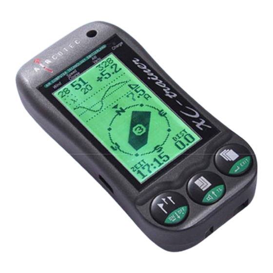
Manual V1.00_2009_V5 1. XC-Trainer Technical Specifications 1.0 Technical description XC-Trainer Loudspeaker XCT Fixation Identification plate with Serial number Key (Key1- Key2 - Key3) Safety lanyard fixation Speedboard USB and Charger connection Speed sensor Page 10... -
Page 11: Altiude
Manual V1.00_2009_V5 1. XC-Trainer Technical Specifications 1.1 Altitude display -1000m to +8200m, resolution 1m 1.2 Vario display Digital indication from -90.0 m/s to +90.0 m/s Analog indication from 0 – 5m/s and 5 – 9,5m/s Acoustic signal for climbing initiates at +0.1m/s Acoustic signal for sink can be set to initiate between –0.1m/s and –5m/s.s Settings in MENU/SETTINGS/VARIO From –5m/s a sink alarm will be... -
Page 12: Xc-Trainer Firmware
Manual V1.00_2009_V5 2. XC-Trainer Firmware 2.1 Firmware Version V1.00 -2009 Info for version Firmware may be found at www.aircotec.com 2.2 Flight Recorder The integrated flight recorder saves position, altitude, climb/sinkrate, SOG, TAS (with speed sensor), heading and temperature (only XCT- Easy+) every second for up to 18 hours 2.3 Waypoints... -
Page 13: Important Information
Manual V1.00_2009_V5 3.Important Information Important! Please read before using the Instrument 3.1 Charging the integrated battery The instrument must be charged before the first use. At the time of delivery, the battery is charged to 50% (this is the ideal condition for a Li-Ion battery) Only charge using the charger delivered with your XC-Trainer. -
Page 14: Key Function -Overview
Manual V1.00_2009_V5 4. Key function - overview Key 1 Key 2 Key 3 Switch ON : By pressing for > 0,3sec ---------------------------------- In Start Menu: In Start Menu: In Start Menu: > Manual start > MENU: > OFF: Flight recorder In main menu Switch the instrument off ----------------------------------... -
Page 15: Switching The Xc-Trainer On/Off
Manual V1.00_2009_V5 5.0 Switching the XC-Trainer ON/OFF To switch on: Press Key1 for app. 0.3 seconds -> The SwitchOn display is shown for 4 seconds, then it switches to the Start Menu Switch ON Display Start Menu (B0) Instrument Type ca.4sec Date Software... -
Page 16: Flight Recording Menus
Manual V1.00_2009_V5 Flight recording menus 6.1 Menus-displays overview: The flight mode contains 3 screens. The following screenshots are examples from flight and do not match the screen NOTE: at launch. BaroCompass Display (Ill. 1) (Details 8.4) The default screen to appear when a new flight is initiated is the BaroCompass screen. -
Page 17: Key Function In Flight Recording Mode
Manual V1.00_2009_V5 7. Key function in Flight Recording mode 7.1 General Toggle between the available displays/screen by pressing Key3 7.2 Set MARK only in the thermal display Any interesting spot (thermals etc.) can be instantly marked using Key1 . The Position Marks are consecutively marked from 1 through 3. -
Page 18: Automatic Start
Manual V1.00_2009_V5 8.0 Automatic-Start Flight recording 8.1.1 Acquiring GPS signal As soon as the instrument is switched on it begins acquiring GPS signal. First available is a 2D position fix, followed by 3D. 2 D Mode < 4 Satellites and no GPS altitude 3 D Modus >= 4 Satellites, GPS altitude. -
Page 19: Manual Start
Manual V1.00_2009_V5 8.2 Manual Start flight recording The flight recording may also be initiated manually from the Switch-On menu, 8.2.1 Manual Start The flight recording may also be initiated before the instrument has acquired a position fix START flight recording: Click Key2 to go to the flying screens The actual recording will however only commence once the... -
Page 20: Ordinary Flight Recording
Manual V1.00_2009_V5 8.3 Ordinary Flight recording The top half of th isplays 1, 2 and 3 ha s the following info: Speed Over Ground (SOG) Alti (only screens 1 and 2) Wind speed Vario Digital (only screens 1 and 2) Wind direction North up Volume indicator... -
Page 21: Barocompass-Mode
Manual V1.00_2009_V5 8.4 BaroCompass flyin g M DE Lower half of display BaroCompass screen shot (I ll. 1) Barogram from the last 10 Minutes +/-500 m, A visible ‘A’ here means the instrument is set to utomatically toggle between Thermal and Ba roCompass screens. -
Page 22: Thermal Mode Windspeed Curve
Manual V1.00_2009_V5 8.5 Thermal flying Mode 8.5.1 Wind distribution curve The wind distribution curve only becomes visible in the display once the pilot has flown at least a full circle, or a figure-eight. The instrument uses the SOG to calculate wind speed and –direction. -
Page 23: Thermal Help Display
Manual V1.00_2009_V5 8.6 Thermal flying MODE 8.6.1 Thermal display The Thermal-display (Ill. 2) The cloud-map of the thermal and the active waypoint is always shown in track up. The lower half of the screen shows the flying arena as a square of either 1x1km or 2x2km. -
Page 24: Large Vario Display
Manual V1.00_2009_V5 8.7 VARIO flying MODE 8.7.1 Large Vario display (B2) Large Digital Vario to ALT in m or Flight direction depiction: +/- 20m/sec using the Square = Bearing to Dual sensor, Altimeter either Launch, Mark, +/- 20-99m/sec using Waypoint GPS calculation Wind speed and - direction... -
Page 25: Menu Screens Overview
Manual V1.00_2009_V5 9. Menu Descriptions 9.1 Menu screens overview Manual altitude set (Details 10.1) or KEY2 Select with Key1 confirm with, Key3 Settings menu Landing search Store land ng (Details 11.1) (Details 11.2) Emergency position Log book Send flight to PC (Details 17.0) (Details 12.1) (Details 12.2) - Page 26 Manual V1.00_2009_V5 9. Menu Descriptions 9.2 Text descriptions Key functions: 1. Use Key1 or Key2 to place Cursor 2. Use Key3 to call a particular setting 3. Use Key1 or Key2 to increase or reduce values, or for Y/N 4. Use Key3 to confirm and activate changes Main Menu: Description...
-
Page 27: Setting Altitude
Manual V1.00_2009_V5 10. Setting altitude manually 10.1 Alti-set Provided the launch altitude is known it may be calibrated before launch in MENU / ALTI SET QNH display: For the QNH-display (in hPa) to be correct, the altitude must be calibrated before launch. QNH is only displayed up until app. 2000m, as QNH per definition looses significance above this altitude. - Page 28 PC software. Two protocols are available: MXP > for the free program „MAX Punkte“ TNC > Aircotec Software TN-Complete Details from page 33 EXIT > Back to main menu Page 28...
-
Page 29: All Flight
Manual V1.00_2009_V5 13.0 ALL FLIGHTS menu Go to this menu to view all flights, even those deleted from the log book. The flights remain visible here until they are pushed out by new flights in an 18h circular storage. A maximum of 124 flights may be stored, after that the oldest ones are pushed out by new flights. -
Page 30: Vario Settings
Manual V1.00_2009_V5 15.0 VARIO-SETTINGS General SETTINGS 1. Bring the cursor to the desired position using Key1 or Key2 2. Use Key3 to call a particular field to set 3. Use Key1 or Key2 to increase/decrease values or to confirm/ cancel (Y/N) 4. -
Page 31: Vario Null
Manual V1.00_2009_V5 15. VARIO-settings 15.7 Vario- null NOTE! Only perform the Vario Nulling in a closed room! Wait app. 5 minutes after switching the instrument on – this allows the instrument to stabilise. Analog display from +/- 0 – 1m Digital Vario with 1cm resolution Actual barometric altitude Vario correction value from 0-100... -
Page 32: Coordinate
Manual V1.00_2009_V5 16. Emergency Coordinates 16.1 Coordinates In case of an emergency, or simply for information, the instrument has the option to display coordinates to be passed on via telephone. The same screen displays the joint European emergency telephone number. ... - Page 33 Manual V1.00_2009_V5 17. Load flights to PC using Aircotec TN-Complete 17.1 Step 1, establish connection to PC: Connect the cable to the Windows PC PC with serial port: The serial - RS232 cable is automatically detected. PC with USB-port: When using the USB cable (XC-TrainerEasy+ )
- Page 34 Manual V1.00_2009_V5 17. Load flights to PC using Aircotec TN-Complete Use the menu General – Interface to enter the COM port allocated to the transfer by your operating system. Find the Com Port for your cable Serial RS232 ...
- Page 35 Manual V1.00_2009_V5 17. Load flights to PC using Aircotec TN-Complete Open the Device Manager in the popup window The actual COM port may be found under USB control units (laptops) The serial RS232 cable is generally allocated the COM 1.
- Page 36 Manual V1.00_2009_V5 17. Load flights to PC using Aircotec TN-Complete Now the only thing missing is the nine- digit software license number – enter this number 17.4 Step 4, transferring a flight to TN-Complete: Start the XC-Trainer Go to MENU/FLIGHTS and select the flight you wish to analyse using SEL ...
- Page 37 Manual V1.00_2009_V5 17. Load flights to PC using Aircotec TN-Complete Press SEND, the transfer protocol appears To transfer to TN-Complete select TNC 1s 57K. The format 9,6 K will also work, albeit slower For other software select the...
- Page 38 Manual V1.00_2009_V5 17. Load flights to PC using Aircotec TN-Complete to initiate the transfer Use Key3 The system shows the transfer progress on the lower screen line Enter a name for the flight data (for ex.. XCT-FLIGHT). Confirm with OK...
- Page 39 Manual V1.00_2009_V5 17. Load flights to PC using Aircotec TN-Complete The flight is loaded into TN-Complete and displayed. The exact descriptions of the many functions may be found in the software manual, accessible under Menu/Open Manual, or by pressing F1...
-
Page 40: Accessories
Manual V1.00_2009_V5 18. Accessories Type: Description: XC-leg fixation XC_BH XC-hangglider fixation XC_DH XC-pg harness fixation XC_GZH XC-instrument bag XC-Etui license TN-Complete XC-Speed-USB USB cable via Speedboard XC-SS-DGH-K XC-SS-DGH-L Speed sensor with attachment for hang- and paraglider with short cable K (50cm) or long cable L (120cm) Speed sensor with stabiliser (cable XC-SS-mS... - Page 41 Manual V1.00_2009_V5 flight instruments Aircotec flight instruments GmbH Alteggerstr. 8 A-8083 St.Stefan i/R AUSTRIA Aircotec GmbH Postfach 56 CH-6048 Horw Schweiz www.aircotec.com Page 41...
Need help?
Do you have a question about the XC-trainer Series and is the answer not in the manual?
Questions and answers