Table of Contents
Advertisement
Quick Links
Advertisement
Table of Contents

Related Manuals for Troxler ICO 4740

Summary of Contents for Troxler ICO 4740
- Page 1 Manual of Operation and Instruction Troxler ICO™ NCAT Oven (Model 4740) Troxler Electronic Laboratories, Inc. 3008 Cornwallis Rd. • P.O. Box 12057 Research Triangle Park, NC 27709 Phone: 1.877.TROXLER Outside the USA: +1.919.549.8661 Fax: +1.919.549.0761 www.troxlerlabs.com...
- Page 3 Troxler products are protected by US and foreign patents. Copyright 2013-2019 Troxler Electronic Laboratories, Inc. All Rights Reserved No part of this manual may be reproduced or transmitted in any form or by any means, electronic or mechanical, including...
- Page 4 Waldstrasse 4, D.82239 Alling nr. 1F, Bldg G, No. 1 Guotai North Road Munich, Germany ZJG, China, 215600 Phone: ++ 49.8141.71063 Phone: 0086.512.56793702 Fax: ++49.8141.80731 Fax: 0086.512.56793701 To locate an independent, Troxler-authorized service partner near troxler@t-online.de kjin@troxlerlabs.cn you, call 1.877.TROXLER (1.877.876.9537).
- Page 5 ABOUT THIS MANUAL The Troxler ICO NCAT Oven (Model 4740) Manual of Operation and Instruction provides detailed information about the oven. The manual includes product safety information, as well as instructions for selecting an installation site, installing the oven, and using the oven to burn hot-mix asphalt (HMA) samples and to store sample data.
- Page 6 Appendix A, Maintenance and Service – Provides maintenance and service information, as well as instructions on basic troubleshooting. Appendix B, Menu Map – Shows a map of the menus in the oven control software. Appendix C, Specifications – Contains the environmental, performance, electrical, and mechanical specifications of the oven.
- Page 7 2. Do not attempt to operate the oven before reading this manual and the safety warnings posted on the unit. Troxler stresses that the user is solely responsible for ensuring the safe use of the oven. Neither the manufacturer, its subsidiary, distributors, nor...
- Page 8 CONVENTIONS USED IN THIS MANUAL Throughout this manual the following symbols and special formatting are used to reveal the purpose of the text. WARNING! Warnings indicate conditions or procedures that, if not followed correctly, may cause personal injury. CAUTION Cautions indicate conditions or procedures that, if not followed correctly, may cause equipment damage.
-
Page 9: Table Of Contents
TABLE OF CONTENTS CHAPTER 1: INTRODUCTION TO THE ICO ....1-1 INTRODUCTION ..................1-2 FEATURES ....................1-4 UNPACKING AND INSPECTING ............1-9 CHAPTER 2: PRODUCT SAFETY INFORMATION ..2-1 INTRODUCTION ..................2-2 CAUTIONS AND WARNINGS ............... 2-4 SAFETY WARNINGS ................2-6 CHAPTER 3: INSTALLATION ........ - Page 10 OVEN MAIN MENU ................. 5-2 BURN SETUP MENU ................5-4 AUTO-TIMER ..................5-16 PROJECT MENU ..................5-21 CORRECTION MENU ................5-22 SCALE MENU..................5-23 STATUS MENU ..................5-24 STORE FUNCTION ................5-27 MISCELLANEOUS MENU ..............5-31 CHAPTER 6: CALIBRATION ........6-1 CORRECTING %AC MEASUREMENTS ..........
- Page 11 APPENDIX C: SPECIFICATIONS ........C-1 ENVIRONMENTAL CONDITIONS ............C-2 PERFORMANCE SPECIFICATIONS ............. C-3 ELECTRICAL SPECIFICATIONS ............. C-4 MECHANICAL SPECIFICATIONS ............C-5 INDEX WARRANTY...
- Page 12 LIST OF FIGURES Figure 1: Parts and Accessories ............1-8 Figure 2: Basket Carrier ................2-9 Figure 3: Overall Schematic for Exterior Wall and Roof Penetrations ....................3-6 Figure 4: Exterior Wall Penetration Using a Metal Elbow and Cap ........................3-6 Figure 5: Exterior Wall Penetration Using a Metal Wall Cap with Screen ......................
- Page 13 Figure 21: Disengage Paper Spindle ..........A-10 Figure 22: Insert New Paper Roll ............A-11...
-
Page 15: Chapter 1: Introduction To The Ico
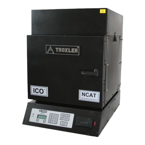
Chapter 1: INTRODUCTION TO THE ICO This chapter provides a brief overview of the ICO. This information includes a list of the parts and accessories, as well as instructions for unpacking and inspecting the oven upon receipt. -
Page 16: Introduction
(HMA) by the Ignition Method). The oven can also be used in conjunction with a nuclear asphalt content gauge, such as Troxler Models 3241–D, 3241 USS, and 3242. The nuclear gauge provides a fast method of measuring the %AC when the aggregate gradation is not needed. The oven can be used when a job requires aggregate gradation. - Page 17 Do not attempt to operate the oven before reading this manual and the safety warnings posted on the unit. Troxler stresses that the user is solely responsible for ensuring the safe use of the oven. Neither the manufacturer, its subsidiary, distributors, nor...
-
Page 18: Features
FEATURES The oven incorporates a number of features that provide unparalleled efficiency, safety, usability, and flexibility. The oven can be powered from a 208–240 V AC, 50/60 Hz, 30 A source. The oven is therefore convenient for use in construction trailers, where power sources may be limited. - Page 19 Oven Keypad and Internal Logic The oven keypad and internal logic provide control, data storage, and output flexibility. The keypad enables the operator to set up and operate the oven, to store sample data, to calibrate and verify the integrated scale, and to enter correction factors. Auto-Timer The oven includes an Auto-Timer function that can preheat the oven automatically based upon start and stop dates and times...
- Page 20 Aggregate Correction Factors The oven stores up to twenty user-defined aggregate correction factors (ACFs), which are percentage values used to adjust the measured asphalt content for specific aggregates. Measurement Displays During a burn cycle, the oven displays measurement units of percent loss (%Loss).
- Page 21 9. Insulated gloves1 (not shown) protect hands and forearms when moving the heated sample basket(s). 10. The Troxler ICO NCAT Oven (Model 4740) Manual of Operation and Instruction (not shown) details how to operate and maintain the oven.
-
Page 22: Figure 1: Parts And Accessories
Figure 1: Parts and Accessories... -
Page 23: Unpacking And Inspecting
UNPACKING AND INSPECTING NOTE To ensure the safe return of the oven to Troxler for repair or maintenance, please keep the original shipping box, pallet, and all packing materials. The box folds for easy storage. Upon receiving the oven from the factory: 1. - Page 24 Clamp, 4-inch hose • Brush, soft-bristle • Operation and Instruction Universal Serial Bus (USB) Troxler ICO NCAT Oven (Model 4740) Manual of • flash drive Material Safety Data Sheet (MSDS) Information Kit 6. Inspect the outside surfaces of the oven and accessories •...
-
Page 25: Chapter 2: Product Safety Information
Chapter 2: PRODUCT SAFETY INFORMATION This chapter provides basic product safety information concerning the ICO, as well as cautions and warnings related to the safe use of the oven. -
Page 26: Introduction
INTRODUCTION The ICO is designed to be safe for the user. The system uses modern, refractory ceramic fiber (RCF) materials to provide highly efficient insulation of the heated chambers. This material is completely enclosed and should present no health risk to the operator during normal use in accordance with this manual. - Page 27 For disposal information, please refer to the MSDSs enclosed recommended protective measures, and health hazard information. with the product. If you have any questions regarding these MSDSs, please contact the nearest Troxler Service Center, as listed on pages ii.
-
Page 28: Cautions And Warnings
CAUTIONS AND WARNINGS LOWER REAR OF OVEN (IDENTIFICATION OF INTERCONNECTS) Cable for 208–240 V AC, 50/60 Hz power to the oven. • The oven power source must have a reliable earth ground connection, or a hazardous condition may occur • during oven operation. - Page 29 TOP OF OVEN Upper surfaces of the oven are hot and will cause burns to unprotected skin. • During normal operations, the chamber door cannot be opened during a burn cycle. However, if the door lock • should fail or be defeated by the operator, it may be possible to open the door while combustion is occurring inside the oven.
-
Page 30: Safety Warnings
SAFETY WARNINGS The ICO is a safe, durable unit. Troxler cannot anticipate every example of improper or unauthorized use of this oven that may lead to malfunction or accident. If a particular use is not specifically mentioned in this manual as authorized, then assume that the use is unauthorized and improper. - Page 31 from the top of the door. Therefore, there must be at least 91 cm (3 ft) of clearance above the oven. Locate the oven no more than 1.2 m (4 ft) from the required electrical power source (see Appendix C). •...
- Page 32 Do not attempt to dry any aggregates mixed with volatile chemicals. • Obtain and use appropriate safety equipment. • Troxler recommends wearing a face shield when handling hot substances and operating the oven (not • supplied). Always wear heat-resistant gloves when handling hot substances.
-
Page 33: Figure 2: Basket Carrier
Do not touch the interior or exterior oven surfaces (except door and control panel) for an extended period after use. Only qualified personnel (Troxler service representatives) should perform service and • maintenance on the oven when disassembly is required. - Page 34 Allow the oven to cool completely before performing service or maintenance. • Soot may build up in the exhaust connector and pipe. Troxler recommends that the exhaust plenum box be • cleaned after every 30 burn cycles, as described on page A-5.
-
Page 35: Chapter 3: Installation
Chapter 3: INSTALLATION This chapter provides instructions on site selection and installation of the ICO. -
Page 36: Site Selection
SITE SELECTION After unpacking and inspecting the ICO as described in Chapter 1, select a suitable site for installation. Apply the following criteria when selecting a site for the oven: The oven must be installed in a well-ventilated room with access to a fume hood or other suitable ventilation •... - Page 37 OVEN INSTALLATION follow the steps below: CAUTION Troxler has optimized the airflow in the oven to ensure efficient combustion. Do not attach the exhaust duct directly to a central exhaust unit. An increase in suction due to external exhaust fans can affect the oven performance.
- Page 38 NOTE The unit will use a 30 to 50 A plug. (It is shipped without a plug.) Troxler recommends a 50 A power supply circuit. 8. Set up the oven as described in Chapter 4.
-
Page 39: Exhaust System Installation
EXHAUST SYSTEM INSTALLATION To ensure the safe and efficient operation of the oven, the oven exhaust system must be installed according to the guidelines contained in this section. These guidelines were prepared according to the Uniform Mechanical Code, Section 914(b). While every installation is unique, these instructions provide general guidelines on proper installation of the exhaust system. -
Page 40: Figure 3: Overall Schematic For Exterior Wall And Roof Penetrations
Figure 3: Overall Schematic for Exterior Wall and Roof Penetrations Figure 4: Exterior Wall Penetration Using a Metal Elbow and Cap... -
Page 41: Figure 5: Exterior Wall Penetration Using A Metal Wall Cap With Screen
NOTES: 1. Seal all joints between wall and thimble and between thimble and duct with a high-temperature caulk. 2. The minimum thickness of all galvanized metal parts is 28 gauge, or that which is called for in local building codes, whichever is thicker. 3. - Page 42 NOTES: 1. Seal all joints between wall and thimble and between thimble and duct with a high-temperature caulk. 2. The minimum thickness of all galvanized metal parts is 28 gauge, or that which is called for in local building codes, whichever is thicker. 3.
-
Page 43: Figure 6: Roof Penetration
Figure 6: Roof Penetration NOTES: 1. Galvanized metal thimble must extend at least 23 cm (9 in.) above and below roof. 2. Galvanized metal thimble must provide at least 15 cm (6 in.) of clearance between the duct and the nearest combustible material. -
Page 44: Figure 7: Exhausting To A Fume Hood
7. Do not locate exhaust point near air intakes for building. Refer to local building codes and/or a licensed HVAC contractor for recommended/required distance. 8. No component shall have a damper, screen, louver, or other such device that may become clogged with soot over time. - Page 45 NOTES: 10. Consult fume hood manufacturer regarding proper installation of the hood. 11. Fasten 4-inch flexible duct to wall or fume hood so that the oven exhausts under the hood. If the fume hood is equipped with a fan or blower, place the end of the flexible duct at least 45 cm (18 in.) away from the intake to the fan or blower.
-
Page 46: Installation With An Exhaust Hood
INSTALLATION WITH AN EXHAUST HOOD AIR VELOCITY In most cases, the exhaust pipe from the ICO extends into the open hood area above the hood intake edge. The air velocity at the hood intake edge must be sufficient to prevent smoke from escaping. -
Page 47: Figure 9: Ico Exhaust Pipe Extended Into The Hood
Measure the airflow lift and adjust the louvers as applicable. (The ideal range is between -2.5 and -3.5 grams.) NOTE If you have trouble getting satisfactory airflow lift values, contact 1.877.TROXLER (1.877.876.9537). Figure 9: ICO Exhaust Pipe Extended into the Hood 3-13... - Page 48 Airflow Draw Test 1. Turn off the hood exhaust fan. 2. Measure the unit’s airflow lift with only its fan running. (For information about measuring the airflow lift, see page 3-19.) 3. Turn on the hood exhaust fan. 4. Measure the unit’s airflow lift with both its fan and the hood exhaust fan running.
-
Page 49: Installation Without An Exhaust Hood
INSTALLATION WITHOUT AN EXHAUST HOOD NOTE The ideal configuration utilizes an exhaust hood, which eliminates the effects of positive or negative air pressure in the environment. However, the ICO is tolerant and should perform well in most situations. POSTIVE AND NEGATIVE AIR PRESSURE Positive Air Pressure Many air handling systems pump air from the outdoors into a building, which creates positive air pressure. - Page 50 NOTE If you have trouble getting satisfactory airflow lift values, contact 1.877.TROXLER (1.877.876.9537). EXHAUST PIPE LENGTH The length of the exhaust pipe must be less than fifteen feet. Anything longer will create excessive back pressure on the unit.
-
Page 51: Figure 10: External Duct Cover (Open Design)
Figure 10: External Duct Cover (Open Design) A design that is not open (e.g., one that incorporates louvers) will create back pressure on the exhaust line (see the figure below). Figure 11: External Duct Cover (Closed Design) NOTE If a screen is added to keep out birds, etc., it needs to be cleaned periodically or soot will build up that will eventually cause back pressure. -
Page 52: Airflow Lift
AIRFLOW LIFT NOTE Airflow is very important for fast and complete burns. Perform the procedure in this section before the first burn. NOTE The unit was configured at the factory and requires very little setup before the first burn. Air enters the chamber through the hole in the bottom of the furnace where the loadcell (scale) supports are positioned. -
Page 53: Figure 13: Exhaust Plenum Box And Louvers
NOTE You can adjust the airflow by moving the louvers on the exhaust plenum box, which is located under the black box at the top of the furnace. (Closing the louvers increases the airflow.) However, the louvers are preset at the factory and should not need adjustment. - Page 54 a. Ensure that there is little or no air movement or vibration in the room. b. Turn off all fans and air conditioning if possible. If you cannot turn them off, position the furnace so that no air is blowing in its direction. NOTE The scale is very sensitive.
- Page 55 NOTE If the scale does not return to 0.0 grams after repeated tries, recalibrate it. If this does not resolve the issue, contact 1.877.TROXLER (1.877.876.9537). 11. Adjust the louvers as applicable based on the value recorded in step 8. If the value is low, chose the louvers slightly from their current position and go back to step 4.
-
Page 56: Exhaust Leaks
EXHAUST LEAKS Leaks in the exhaust system are annoying and somewhat dangerous. The smoke emitted from any furnace contains many noxious gases that are unsafe to breathe over an extended period. When the unit is set up properly, there should not be any exhaust smell in its vicinity. -
Page 57: Chapter 4: Setup And Operation
Chapter 4: SETUP AND OPERATION This chapter provides information on using the ICO. It describes the oven keypad and provides procedures for starting up the oven and setting it up for the first time, daily startup and operation, and shutting the oven down. The procedures in this chapter are general in nature. -
Page 58: Keypad
KEYPAD Figure 14 shows the layout of the oven keypad. The table lists the function of each key. Figure 14: Oven Keypad FUNCTION Returns to the next higher-level menu without updating or storing data. In response to yes/no 〈ESC〉 questions, has the same effect as pressing 〈NO〉. - Page 59 (Printer Optional) Commands the internal printer to advance the paper by several lines (as 〈PAPER FEED〉 opposed to the paper feed button on the printer, which advances the paper as long as it is Tares the integrated scale. Available when 〈TARE〉...
-
Page 60: Printer
PRINTER The following figure shows the front panel of the oven printer. Figure 15: Printer Front Panel The paper feed button activates the paper feed mechanism. Paper continues to feed until the button is released. For information on replacing the printer paper, refer to REPLACING THE PRINTER PAPER on page A-9. -
Page 61: First-Time Startup And Setup
FIRST-TIME STARTUP AND SETUP WARNING To prevent personal injury or equipment damage, the operator should become familiar with the safety warnings and information in Chapter 2 before operating the ICO. This section summarizes the initial startup and setup of the oven. - Page 62 NOTE When the default screen is displayed, the up and down arrow keys can be used to adjust the display contrast. 3. Press 〈 MENU 〉 to display the MAIN MENU. 4. From the MAIN MENU, press ( 5 ) to access the Scale Menu.
- Page 63 press ( 3 ) . For more information, refer to page 5- d. Press ( 4 ) to enter the customer name. For more e. The oven features a System Information function that information, refer to page 5-35. outputs a listing of operating parameters to the serial communications port once each second, either anytime the oven is powered on or only during a burn cycle.
- Page 64 8. Press ( 2 ) to set up the Auto-Timer feature, if desired. The Auto-Timer automatically powers the heating element on and off based upon start and stop times and dates entered by the operator. For more information, refer 9. Determine the aggregate correction factors (ACFs), if to page 5-16.
-
Page 65: Daily Startup And Operation
Chapter 2 before operating the ICO. Troxler recommends the following method for burning samples. For additional information, refer to the following ASTM or American Association of State Highway and Transportation Officials (AASHTO) standards: ♦... - Page 66 designated start time. To set up the Auto-Timer, see page 5-16. Note that opening the chamber door prohibits the oven from applying power to the heating element. 2. Press (STATUS). From the status display, check that the following parameters and functions are configured as desired, and then press (ESC) to return to the default display.
- Page 67 5. If the mixture is not soft enough to separate with a spatula or trowel, place it in a large, flat pan and warm in an oven set at 110 ± 5 C until it can be separated or mixed. Split or quarter the material in accordance with °...
-
Page 68: Figure 16: Sample Basket Assembly
WARNING Always wear heat-resistant gloves when handling any hot substance. Troxler recommends wearing a face shield when the oven door is open and when handling the sample. Use the basket carrier to move hot sample baskets (see Figure 2 on page 2-9). Always keep the basket carrier to the left side of your body, with the handle between your body and the open oven door. - Page 69 11. The oven displays: Place Sample in chamber and close door. xxx.x g Then press START. Wearing heat-resistant gloves and a face shield, use the basket carrier to place the sample with the baskets and catch pan on the hearth plate in the center of the oven.
- Page 70 13. When the mass loss does not exceed 0.01% of the sample mass (W ) for three consecutive one-minute periods, the burn is complete. The oven displays the results of the burn as shown below. If five minutes have elapsed since the chamber temperature has peaked, the oven also releases the door lock, lights the red BURN COMPLETE indicator, and sounds the annunciator.
- Page 71 WARNING! Clean ICO Exhaust System. See Operation Manual for details. Press ENTER When this warning is displayed, press ( ENTER ) to continue with the remainder of this procedure. Upon completion, clean the exhaust plenum box as described on page A-5. 14.
-
Page 72: Daily Shutdown
DAILY SHUTDOWN To power down the oven: If the Auto-Timer function is disabled, position the on/off rocker switch on the right-hand side of the front panel to the off position (1 for on, 0 for off). The front panel display will be dark. -
Page 73: Chapter 5: Main Menu
Chapter 5: MAIN MENU The operator controls and configures the ICO from the MAIN MENU, its submenus, and displays. This chapter describes the many menu options. -
Page 74: Oven Main Menu
OVEN MAIN MENU WARNING To prevent personal injury or equipment damage, the operator should become familiar with the safety warnings and information in Chapter 2 before operating the ICO. The oven control software includes a number of options that can be configured by the operator for greater flexibility of operation. - Page 75 submenus of their own. A complete map of these menus is provided in Appendix B of this manual. The remainder of this chapter describes each menu option, except for the Project option, which is described in Chapter 7, and the Corr. Factors and Scale options, which are described in Chapter 6.
-
Page 76: Burn Setup Menu
BURN SETUP MENU The Burn Setup Menu is used to configure the parameters of the burn mode and to turn the Auto-Print and Auto-Store functions on or off. To display the Burn Setup Menu, press ( 1 ) at the MAIN MENU. The oven displays: Burn Setup Menu 1. - Page 77 Burn Parameter Menu↕ 4. Calculation Type Burn Mode To select the burn mode, press at the Burn Parameter Menu. The oven displays: Choose Burn Mode 1. Program Time 2. Auto-Control To configure the oven to burn for a specified number of minutes, press .
- Page 78 the production mixture. Burn the test sample until it is clean (free of coke, the solid binder residue). NOTE Using the Auto-Control with cutoff limit of 0.01% or 0.1 g will accomplish a clean burn test sample. Use the time required to produce a clean test sample as the burn time.
- Page 79 To enter a cutoff limit, press at the Burn Parameter Menu shown on page 5-4. The oven displays: Cutoff Units 1. Grams 2. Percentage CUTOFF LIMIT IN GRAMS. To enter the cutoff limit in grams, press . The oven displays: Current Cutoff Limit X.X g do you want to...
- Page 80 To exit without changing the cutoff limit, press . The oven returns to the Burn Parameter Menu. To change the cutoff limit, press . The oven displays: Enter Cutoff Limit from 0.001% - 1.000% in 0.001% steps _ Use the numeric and decimal keys to enter a cutoff limit from then press ENTER 0.001% to 1.000% in increments of 0.001%.
- Page 81 To select the desired calculation type, press 〈4〉 at the Burn Parameter Menu shown on page 5-4. The oven displays: Calculation Type 1. Bitumen to Sample 2. Bitumen to Agg Use the numeric keys to select the desired calculation type. The oven sets the calculation type and returns to the Burn Parameter Menu.
- Page 82 If the user selects (1), the display below is momentarily displayed before returning to the Burn Setup menu. Chamber Temp set to: 540C (default) If the user selects (2), the display below will appear: Enter Chamber Temp Within 200C – 600C Temp set to _ C The user enters the desired temperature, presses Enter;...
- Page 83 To return to the Burn Setup Menu without changing the Auto-Print status, press To turn the Auto-Print function on, press . The oven displays: Do you want to output in REDUCED format? To enable a reduced printout, press (YES); to enable a standard printout, press (NO).
-
Page 84: Figure 17: Sample Reduced Printout
Figure 17: Sample Reduced Printout AUTO-STORE The Auto-Store function automatically stores sample data upon completion of a burn cycle. The data is stored under the active project, using a sequential auto-sample ID number. When a new project is created, the sample ID number for the Auto-Store function starts at 1 and is incremented each time a sample is stored automatically. - Page 85 IDs 3, 4, and so on. To prevent duplication of sample ID numbers, Troxler recommends either using sample IDs beginning at 100 or higher when storing sample data manually or always enabling the Auto-Store function.
- Page 86 To turn the Auto-Store function off, press . The oven updates the Auto-Store status, displays a brief confirmation message, and returns to the Burn Setup Menu. Active Project Selected If the operator attempts to turn the Auto-Store function on and a project has been selected as active, the oven enables the Auto- Store function, briefly displays the confirmation message shown below, and then returns to the Burn Setup Menu.
- Page 87 No Project Selected If the operator attempts to turn the Auto-Store function on and one or more projects have been created (see Chapter 7) but no project has been selected as active, the oven displays: Auto-Store requires an active project 1.
-
Page 88: Auto-Timer
AUTO-TIMER The Auto-Timer function can be used to automatically power the heating elements on and off at specified times and on specified days. NOTE When the Auto-Timer powers down the heating element, the control electronics and exhaust fan remain powered. NOTE In the Auto-Timer mode, the oven will not turn off at the programmed time if a burn cycle is in progress. - Page 89 mm/dd/yyyy Input Start Date The top line of the display shows the current setting for the start then press ENTER date. The date format (in this example, mm = month, dd = day, and yyyy = year) is the same as that displayed on the default screen.
- Page 90 hh:mm AM Arrows toggle AM/PM Input Start Time The top line of the display shows the current setting for the start then press ENTER time. The time format (in this example, the AM/PM format) is the same as that displayed on the default screen. To change the time format, refer to page 5-34.
- Page 91 Auto Timer Enabled mm/dd/yyyy hh:mm AM mm/dd/yyyy hh:mm PM The oven then returns to the MAIN MENU shown on page 5-2. Skip Weekends DISABLING THE AUTO-TIMER To disable the Auto-Timer, press at the MAIN MENU shown on page 5-2. If the Auto-Timer is active, but has not applied power to the heating element, the oven displays: Auto-Timer is active - do you...
- Page 92 To suspend the Auto-Timer, press . The oven briefly displays the message shown below and returns to the MAIN MENU. Auto-Timer is Suspended must be explicitly The Auto-Timer can also be disabled from this display by reenabled to resume pressing .
-
Page 93: Project Menu
PROJECT MENU The oven stores sample data in project files. The Project Menu enables the operator to create a new project; to select the active project from a list of created ones; and to view, erase, print, or download project data. The functions available from the Project Menu are described in Chapter 7, Handling Data. -
Page 94: Correction Menu
CORRECTION MENU The oven stores up to twenty operator-defined aggregate correction factors (ACFs). The Correction Menu enables the operator to create, select, and erase ACFs. The Correction Menu is described in Chapter 6, Calibration. 5-22... -
Page 95: Scale Menu
SCALE MENU This includes an integrated scale that continuously monitors the sample mass loss during a burn cycle. The Scale Menu enables the operator to tare the scale, either manually or automatically, and to verify and calibrate the scale. The Scale Menu is described in Chapter 6, Calibration. -
Page 96: Status Menu
STATUS MENU The Status Menu allows the operator to view, print, and download system status information. The oven can also be set up to print this status information automatically upon power up. To access the Status Menu, press ( 6 ) at the MAIN MENU shown on page 5-2. - Page 97 ♦ Auto-Timer status (Enabled, Disabled, or Suspended) and settings (if enabled) ♦ Auto-Tare, Auto-Store, and Auto-Status Print status (ON or Use the up and down arrows to scroll through the various OFF) screens. To return to the Status Menu, press NOTE The system status display can also be viewed directly from the default display by pressing the...
- Page 98 wait... When finished downloading, the oven returns to the Status Menu. AUTO-STATUS PRINT The oven can also be configured to automatically print system status information each time it is powered on. To enable this function, press at the Status Menu. The oven displays the Auto-Status Print menu, as shown below: Auto-Status Print 1.
-
Page 99: Store Function
STORE FUNCTION After burning a sample and before burning another sample, sample data can be stored under the active project ID. (See Chapter 7 for details on creating a project ID.) The Store selection from the MAIN MENU enables the operator to store sample data manually. - Page 100 Input new sample number _ then press ENTER Enter a sample number (up to six numerals). Troxler recommends that manually stored samples be numbered beginning at 100 or higher. When the sample number is complete, press If there is sufficient memory, the oven stores the sample data...
- Page 101 NO PROJECT DATA If the operator initiates the Store function and there is sample data to be stored, but no project IDs have been created, the oven displays: No Project Data Do you want to create a project? To return to the previous display without creating a project or storing the sample data, press ...
- Page 102 and then requests the sample number as described in the Active Project Selected section on page 5-28. 5-30...
-
Page 103: Miscellaneous Menu
MISCELLANEOUS MENU The Miscellaneous Menu allows the operator to: ♦ Configure the system time and date parameters ♦ Set the baud rates for the serial communication and auxiliary ports ♦ Select the desired temperature scale ♦ Enter the customer name ♦... - Page 104 TIME/DATE MENU The Time/Date Menu allows the operator to set the current time and date and to select the desired format for the date and time displays. To access the Time/Date Menu, press at the Miscellaneous Menu shown above. Use the up and down arrows to scroll through the menu options.
- Page 105 Set Date at the Time/Date Menu. To set the current date, press The oven displays: mm/dd/yyyy Input Date and Press ENTER (Note that in this example, the time is displayed in mm/dd/yyyy format. To change the date format, refer to the Date Format section on the following page.) To accept the displayed date, press ENTER .
- Page 106 Date Format The oven can display the date in either mm/dd/yyyy or dd/mm/yyyy format, where mm = month, dd = day, and yyyy = year. To select the desired date format, press at the Time/Date Menu. The oven displays: Date Format 1.
- Page 107 Set Baud Rate on 1. Ser. Comm. Port 2. Auxiliary Port Press to set the baud rate for the serial communications port or to set the baud rate for the auxiliary port. The oven displays: Use the numeric keys to select the baud rate that matches that of the peripheral device.
- Page 108 Customer Name is now XXXXXX do you want to change name? To accept the name displayed and return to the Miscellaneous Menu, press To change the customer name, press ↕ To scroll chars YES to select char Enter a customer name using up to sixteen alphanumeric ENTER when done characters.
- Page 109 elect to enable this function anytime the oven is powered on (Always On) or only during a burn cycle (During Burn Only). ♦ Current time ♦ Current chamber temperature in degrees Celsius or Fahrenheit, as selected by the operator ♦ Total mass on the scale ♦...
- Page 110 ABORT PRINT The Abort Print function enables the operator to halt a print operation. To access the Abort Print function, press on the Miscellaneous Menu. The oven displays: Aborting print... Upon completion, the oven returns to the Miscellaneous Menu. UNLOCK DOOR The Unlock Door function allows the operator to unlock the chamber door if the sample burn time is less than 30 minutes or under any other condition from the default screen.
-
Page 111: Chapter 6: Calibration
Chapter 6: CALIBRATION This chapter provides information on calibrating and verifying operating parameters for the ICO. The information includes procedures for determining an aggregate correction factor (ACF); for using the Correction Menu to manage ACFs; and for using the Scale Menu to tare, verify, and calibrate the integrated scale. -
Page 112: Correcting %Ac Measurements
CORRECTING %AC MEASUREMENTS WARNING To prevent personal injury or equipment damage, the operator should become familiar with the safety warnings and information in Chapter 2 before operating the ICO. During the ignition process, a complex interaction of various effects (mass, temperature, airflow, materials type) can produce a result that could be interpreted as a “mass loss.”... - Page 113 • Safety equipment - including but not limited to heat- resistant gloves and face shield • External scale precise to 0.1 g ± • Drying oven that can maintain 105 C (221 F) per ASTM ° ° • D 6307, Standard Test Method for Asphalt Content of Hot- •...
-
Page 114: Figure 18: Sample Aggregate Correction Factor Form
4. Divide the HMA sample into a minimum of three correction samples. 5. Use an external scale to weigh the sample baskets with the catch pan and basket cover. Record the mass (W 6. With the catch pan under the sample baskets, spread the correction sample evenly in the baskets. - Page 115 WARNING Always wear heat-resistant gloves when handling any hot substance. Troxler recommends wearing a face shield when the oven door is open and when handling the sample. Use the basket carrier to move hot sample baskets (see Figure 2-1 on page 2-8). Always keep the basket carrier to the left side of your body, with the handle between your body and the open oven door.
- Page 116 CAUTION Use care when loading and unloading samples to avoid touching or scraping the hearth plate, chamber sides, or heating element. 14. Place the sample with the baskets and catch pan on the hearth plate in the center of the oven. Ensure that the hearth plate and sample baskets do not touch the chamber sides.
- Page 117 CALCULATING AN ACF 1. Using the following equation, calculate and record the aggregate correction factor for each correction sample: ACF =%AC – %AC where: ACF = Aggregate correction factor = Asphalt content of sample as determined by the oven = True asphalt content 2.
-
Page 118: Correction Menu
CORRECTION MENU The oven can store up to twenty aggregate correction factors (ACFs). Each ACF is stored using an alphanumeric ID entered by the operator. The ACF ID can be up to twelve characters. When a correction factor is active, all measurements are adjusted using that correction factor. - Page 119 as active, briefly displays a confirmation message, and returns to the Correction Menu. To enter the desired ACF ID, press ( 2 ) . The oven displays: ↕ to scroll chars YES to select char Enter the desired ACF ID. Use the numeric keys to enter ENTER when done numbers and move the cursor to the next position.
- Page 120 If the maximum number of ACFs does not already exist, the oven displays: ↕ to scroll chars YES to select char Enter the desired ACF ID. Use the numeric keys to enter ENTER when done numbers and move the cursor to the next position. To enter alphabetic characters, use the arrow keys to scroll through the characters.
- Page 121 Erase 1. One ACF 2 . A l l A C F s To erase all ACFs, press and follow the prompts. To erase a single ACF, press . The oven displays: Select 1 . S c r o l l A C F s 2.
-
Page 122: Scale Menu
Selecting, and Specifying Balances and Scales for use in Soil, Rock, and Construction Materials Testing. Please refer to these standards when identifying the accuracy and linearity requirements. Troxler recommends calibrating the scale should it fail the Verify test. To access the Scale Menu, press at the MAIN MENU. - Page 123 To select an item from the menu, press the corresponding number key. Use the up and down arrows to scroll through the menu options. TARE To tare, or “zero” the integrated scale manually, press at the Scale Menu. NOTE The operator can also tare the scale manually by pressing the key when the default screen is TARE...
- Page 124 Press to turn the Auto-Tare function on; press to turn the function off. The oven displays a brief confirmation message and returns to the Scale Menu. VERIFY The oven enables the operator to verify the accuracy of the integrated scale using a known mass. To verify the scale, press at the Scale Menu.
- Page 125 Verification Result XX.XXX % do you want to To print the results, press ; to continue without printing, print result? press If the error percentage is less than 0.025%, the oven returns to the Scale Menu. If the error percentage is greater than ±...
- Page 126 (3-10) then press ENTER The oven enables the operator to calibrate the scale using from two to ten calibration points (weights). Troxler recommends using at least three calibration points. Enter the desired number of calibration points, and then press . The oven...
- Page 127 ENTER ENTER NOTE When calibrating the scale Troxler recommends using a 5000-g ANSI/ASTM Class 4 or NIST Class P mass over that span the range over which the oven will be used. The lowest point of this range should be slightly less than the mass of the unloaded sample pan assembly (approx.
- Page 128 If the number of calibration points is greater than 2, the oven continues to request each mass until all calibration points are complete. The oven then displays: deg of freedom = X CC = X.XXXXX SEE = X.XXXXX where: CC = Correlation coefficient, which indicates the Press Enter...
-
Page 129: Chapter 7: Handling Data
Chapter 7: HANDLING DATA The ICO can store sample data for viewing and projects printing later. This data is stored in . This chapter explains how to use the Project Menu to create, select, view, erase, print, and download projects and data. -
Page 130: Projects
PROJECTS The ICO can store burn data for up to 200 samples. The oven stores sample data in project files under project IDs defined by the operator. Up to 20 project IDs can be defined. The operator manages project files from the Project Menu described in the remainder of this chapter. -
Page 131: Project Menu
PROJECT MENU The Project Menu allows the operator to select (activate) an existing project; to create and activate a new project; to view stored project data, and to erase, print, or download a project. To access the Project Menu, press then . - Page 132 To activate a known project ID, press ( 2 ) at the Select display. The oven displays: ↕ to scroll chars YES to select char Enter a project ID using up to twelve alphanumeric ENTER when done characters. Use the numeric keys to enter numbers and move the cursor to the next position.
- Page 133 the next position. To enter alphabetic characters, use the arrow keys to scroll through the characters. When the desired character is displayed, press ( YES ) to move the cursor to the next position. To move the cursor back one position, press the ( BACK SPACE ) key.
- Page 134 ↕ Sample #xx Burn Time xxx.x m Sample Mass xxxx.x g Mass Lost -xxx.x g ↕ Sample #xx % Loss -x.xxx % AC +x.xxx ACF Use the arrow keys to scroll through the sample data. Value +x.xx % NOTE To print the minute-by-minute burn cycle data for the selected sample, press while the sample ENTER...
- Page 135 Press (1) to scroll through the stored projects, or (2) to enter a known project ID. Follow the same procedures as described in the Select section on page 7-3 to select or enter the ID of the project to be erased. The oven displays: Erase Project PROJECT ID...
- Page 136 Select 1 . S c r o l l P r o j e c t s 2 . E n t e r P r o j e c t I D Press ( 1 ) to scroll through the stored projects, or ( 2 ) to enter a known project ID.
- Page 137 To download project data stored previously, press at the Project Menu. The oven displays: Output 1. One Project 2 . A l l P r o j e c t s To output a single project, press . The oven displays: ...
-
Page 139: Appendix A: Maintenance And Service
Appendix A: MAINTENANCE AND SERVICE This appendix contains information on maintaining and servicing the ICO. -
Page 140: Troubleshooting
Chapter 2 before operating the ICO. If you are unable to determine the cause of a problem after reading the hints below, contact a Troxler Service Center (see page A-12). OVEN DOES NOT TURN ON Ensure that the oven is plugged into an outlet and that the circuit breaker for the outlet is on. - Page 141 THE SCALE SHOWS ERRATIC READINGS Ensure that the baskets do not touch the side of the sample chamber. Contact a Troxler representative for further information. OVEN DISPLAYS: WARNING! Clean ICO Exhaust System. See Operation Manual for details. Press ENTER To ensure the continued safe and efficient operation of the oven, the exhaust system should be cleaned regularly.
- Page 142 Check for ventilation fans in the lab area. Any fan that removes air from the lab could cause the ICO to smoke if the fan is removing a high volume of air from the lab. Check cooling fans, hood fans, etc. Turn off the fan or open an exterior door to help equalize air pressure in the room with outside air pressure.
-
Page 143: Cleaning
WARNING! Clean ICO Exhaust System. See Operation Manual for When this warning is displayed, Troxler strongly recommends details. Press ENTER cleaning the exhaust plenum box as described on the following page. To ensure that the exhaust system has been cleaned, when the... - Page 144 Cannot perform burn. Please clean the plenum before the next burn cycle. If the exhaust plenum box has not been cleaned, press The oven displays the message above and will exit out of the burn cycle cancelling the burn cycle. ...
- Page 145 CAUTION Do not loosen the nuts that secure the louvers to the plenum access panel. Moving the louvers will degrade the factory calibration of the exhaust system. 4. Use a wet/dry vacuum cleaner to clean the soot from the plenum box. The vacuum cleaner should be equipped with a filter that has a rating of 0.6 micron or less.
-
Page 146: Replacing Parts
REPLACING THE LITHIUM BATTERY The oven uses one DL2450 3-volt lithium battery (Troxler PN 15706) to maintain the stored data and real time clock. The oven monitors the battery voltage. If the battery voltage is low, the oven displays a “low battery”... -
Page 147: Figure 19: Opening Bottom Printer Door To Access Paper
6. Install the electronics module. 7. Turn the oven circuit breaker/power switch on and allow the oven to complete its self-test. Upon completion of the self-test, the “low battery” symbol will still be displayed. To reset the “low battery” indication, turn the circuit breaker/power switch off, then on again. -
Page 148: Figure 20: Opening Upper Printer Door To Access Paper
Figure 20: Opening Upper Printer Door to Access Paper 3. Push the two tabs out to disengage the paper spindle as shown in the following figure. Figure 21: Disengage Paper Spindle 4. Insert new paper roll into the printer. Make sure that the paper feeds from the top of the roll and the paper extends past the bottom door opening as shown in the following figure. - Page 149 Figure 22: Insert New Paper Roll 5. Press the paper feed button to ensure that the paper feeds freely. REPLACING FUSES Repair or replacement of fuses should be performed only by qualified service personnel (Troxler Service Representatives). A-11...
-
Page 150: Returning Parts For Service
Items returned for service must be accompanied by an RGA (Returned Goods Authorization) number, and a description of the item and its problem. This information is used by Troxler shipping and service personnel to expedite the repair work. To obtain an RGA number, please call or fax Troxler headquarters at Research Triangle Park, or one of the branch offices with your request. - Page 151 NOTE To prevent order duplication, if an order has been placed by telephone, please write “Confirming Order” on any follow-up written requests. A-13...
-
Page 153: Appendix B: Menu Map
Appendix B: MENU MAP This appendix provides a map of the menus in the ICO control software. -
Page 154: Menu Map Description
MENU MAP DESCRIPTION Figure B-1 is a map of the MAIN MENU of the oven control software and each of its submenus. To access the MAIN MENU, press . Where applicable, the default (as shipped) menu settings are highlighted in yellow. MENU The menu map uses indentation to indicate submenus that result from selection of a menu item. - Page 155 1. Burn Setup MAIN MENU Burn Setup Menu 1. Burn Parameters Burn Parameter Menu 1. Burn Mode Choose Burn Mode 1. Program Time 2. Auto Control 3. Burn Time 2. Set Chamber Temp 3. Cutoff Limit Cutoff Units 1. Grams 2.
- Page 156 2. Off Auto-Timer 1. Sat Skip Any Days? 2. Sun 3. Both 4. None Auto-Timer Enabled 1. Suspend 2. Disable Auto-Timer Suspended 1. Re-enable 2. Disable Project Project Menu 1. Select Select 1. Scroll Projects 2. Enter Project ID Create 3.
- Page 157 1. One Project Select 1. Scroll Projects 2. Enter Project ID 2. All Projects 5. Print Output 1. One Project Select 1. Scroll Projects 2. Enter Project ID 2. All Projects Download One Project Select 1. Scroll Projects 2. Enter Project ID 2.
- Page 158 Erase ACF Erase One ACF Select 1. Scroll ACFs 2. Enter ACF ID All ACFs Scale Scale Menu 1. Tare 2. Auto-Tare Auto-Tare 1. On 2. Off 3. Verify 4. Calibrate Status Status Menu View Print Download Au to-S tatus Pri nt Au to-S tatus Pri nt Store...
- Page 159 8. Miscellaneous| Miscellaneous Menu 1. Time/Date Time/Date Menu Set Time Set Date Time Format Time Format 1. AM/PM 2. 24-Hour Date Format Date Format 1. mm/dd/yyyy 2. dd/mm/yyyy 2. Baud Rate Set Baud Rate on Ser. Comm. Port Baud Rate 1.
- Page 160 3. 2400 4. 4800 5. 9600 Temperature Scale Temperature Scale Celsius Fahrenheit Customer Name System Output System Info Output Always On During Burn Only Abort Print Unlock Door...
-
Page 161: Appendix C: Specifications
Appendix C: SPECIFICATIONS This appendix contains specifications for the ICO. -
Page 162: Environmental Conditions
ENVIRONMENTAL CONDITIONS Indoor –55 to 85 Ambient Storage (–67 to 185 ° Temperature 10 to 50 ° Ambient Operating (50 to 122 ° Temperature 2000 m maximum ° Altitude Rating Main Supply Voltage ± Fluctuation Pollution Degree Installation Category (Overvoltage Category) 92% maximum Humidity... -
Page 163: Performance Specifications
If desired, oven performance can be verified using a precision asphalt mix. The oven thermocouples are calibrated at the factory and do not require re-calibration by the operator. If verification of the thermocouples is desired, Troxler recommends checking their accuracy at room (ambient) temperature. -
Page 164: Electrical Specifications
ELECTRICAL SPECIFICATIONS 120/240 VAC Power sources 6000 VA/7200 VA Peak power consumption 25 A/30 A Current NEMA 6-30 Plug (detached) 1.8 m (6 ft) Length of power cord 4 line x 20 character Liquid crystal display 25-key sealed membrane Keypad Data Terminal Equipment (DTE) RS-232C configuration... -
Page 165: Mechanical Specifications
MECHANICAL SPECIFICATIONS Outside dimensions 24 W x 32D x 33.5 H in Chamber dimensions 13 W x 20 D x 11.5 H in Weight 160 lbs. Sample basket dimensions H in. (each) 8 W x 14.5 D x 1.6 H in. Basket assembly 9.4 W x 15.5 D x 4.3 H in. -
Page 167: Index
INDEX %Loss ... 1-6, 4-13, 5-8, 5-24, Auto-Print 4-7, 5-4, 5-10, 6- AASHTO Standard ..4-9, 4- Auto-Status print ..5-26 15, 6-2, 6-12 Auto-Store 1-6, 4-7, 4-10, 5- abort Auto-Tare ....1-4, 6-13 print ........5-38 Auto-Timer ..1-5, 4-8, 5-16 ABORT Key ......... - Page 168 Calibration ......6-1 Inspecting ......1-9 Catch pan ......1-7 Installation ......3-1 Cleaning Exhaust System ....3-5 Oven ........3-3 Exhaust Plenum Box ..A-5 Site Selection ..... 3-2 Clearning ......A-5 Keypad ......... 4-2 Conventions, manual ..vii Main Menu ......
- Page 169 RGA number ....A-13 Electrical ......C-4 Returning Parts ..... A-13 Environmental Conditions ........... C-2 Safety Information ..2-1 Mechanical ......C-5 Sample Performance ...... C-3 Basket ........1-7 Standard error of estimate basket Cover ...... 1-7 (SEE) ....... 6-18 Baskets .........
-
Page 171: Warranty
TROXLER’s obligation under this warranty shall be limited exclusively to the repair at a TROXLER facility at no charge, except for shipping to and from TROXLER’s plant, of any instrument which may prove defective under normal use and which TROXLER’s examination shall disclose to its satisfaction to be thus defective.
Need help?
Do you have a question about the ICO 4740 and is the answer not in the manual?
Questions and answers