Bosch RG8.0 Repair Instructions
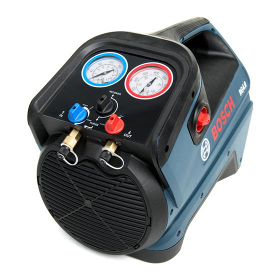
Refrigerant recovery unit
Hide thumbs
Also See for RG8.0:
- Original instructions manual (43 pages) ,
- Original instructions manual (139 pages)
Table of Contents
Advertisement
Advertisement
Table of Contents

Related Manuals for Bosch RG8.0


Summary of Contents for Bosch RG8.0
- Page 1 RG8.0 / RG4.0 en Repair instructions Refrigerant recovery unit...
-
Page 3: Table Of Contents
6.15 Repairs to compressor 6.16 Replacing the copper tube between manifold and compressor outlet / inlet 6.17 Replacing the IEC connector 6.18 Replacing the start relay (only for RG8.0) 6.19 Cleaning the particle filter Bosch Automotive Service Solutions GmbH F 002 DG9 H10... -
Page 4: Symbols Used
4 | RG8.0 / RG4.0 | Symbols used Symbols used On the product In the documentation Observe all warning notices on products and ensure 1.1.1 Warning notices - Structure and meaning they remain legible. Warning notices warn of dangers to the user or people in the vicinity. -
Page 5: Safety Instructions
Danger: Risk of electric shock If moisture enters the refrigerant system, it is likely Touching live parts in the RG8.0 / RG4.0 to cause damage. Cover the ports of RG8.0 / RG4.0 causes fatal electric shock. ¶ with caps after service. -
Page 6: Requirements For Repair
0. Else, replace the pressure gauges (refer chapter 6.5). 3. Switch off the mains supply to the RG8.0 / RG4.0. 4. Disconnect the power cable from the mains supply. 5. Disconnect the other end of the power cable from the power socket of the RG8.0 / RG4.0. -
Page 7: Overview Of Parts
Overview of parts | RG8.0 / RG4.0 | 7 Overview of parts Parts list - RG8.0 Fig. 3: Exploded view of RG8.0 Position Part number Part description Position Part number Part description number number RGB800100 Compressor RGB480230 HMI cover RGB800120... -
Page 8: Parts List - Rg4.0
8 | RG8.0 / RG4.0 | Overview of parts Parts list - RG4.0 Fig. 4: Exploded view of RG4.0 Position Part number Part description Position Part number Part description number number RGB400100 Tube - Manifold to compressor inlet RGB480240 Front Panel... -
Page 9: Additional Parts / Kits
For RG4.0 tion, open the inlet control valve (blue) and outlet control valve (red) valves. 3. Start the RG8.0 / RG4.0 and close the inlet valve. Part number Part Description The RG8.0 / RG4.0 should shut-off due to Low... -
Page 10: Diagnosing Component Failure
10 | RG8.0 / RG4.0 | Troubleshooting Symptom / Checklist Cause/Action Symptom / Checklist Cause/Action Problem Problem RG8.0 / RG4.0 Is the RG8.0 / RG4.0 Verify power to Poor Check if the parti- Clean or replace the does not start plugged into the cor- RG8.0 / RG4.0... -
Page 11: Of Capacitors
5.2.5 Of motor and the motor should be replaced. The RG8.0 / RG4.0 motors are equipped with auto- 5.2.6 Of power switch matic reset type thermal switch. If the motor stops 1. Execute the steps listed in chapter 3.1. -
Page 12: Internal Leak Test
2. Open the inlet valve and close the outlet valve. 3. Remove the knob of the power switch (Fig. 3, Pos. 8) 3. Start the RG8.0 / RG4.0 and allow it to run until it / (Fig. 4, Pos. 9). -
Page 13: Replacing The Manifold Assembly
Repair | RG8.0 / RG4.0 | 13 Replacing the manifold assembly 12. Connect the copper tubings back to the manifold. 13. Restore the electrical connection to the HP and LP pressure switches. 14. Restore the earthing connection to the manifold. -
Page 14: Replacing The Hp Switch
14 | RG8.0 / RG4.0 | Repair Replacing the HP switch Replacing the condenser 1. Execute steps 1 to 8 listed in chapter 6.4. 1. Execute the steps listed in chapter 3.1. 2. Grip the manifold assembly in a bench vise. -
Page 15: Replacing The Fan
Repair | RG8.0 / RG4.0 | 15 6.10 Replacing the fan 6.12 Replacing the capacitors 1. Execute the steps listed in chapter 3.1. 6.10.1 For RG8.0 2. Open the LH and RH enclosures. 1. Execute the steps listed in chapter 3.1. -
Page 16: Replacing The Compressor
16 | RG8.0 / RG4.0 | Repair 6.14 Replacing the compressor 6.17 Replacing the IEC connector 1. Execute the steps listed in chapter 3.1. 1. Execute the steps listed in chapter 3.1. 2. Open the LH and RH enclosures. 2. Open the LH enclosure. -
Page 17: Cleaning The Particle Filter
Repair | RG8.0 / RG4.0 | 17 6.19 Cleaning the particle filter 1. Execute the steps listed in chapter 3.1. 2. Unfasten the LP inlet port. Fig. 7: Cleaning the LP inlet port 1 LP inlet port 2 O-ring 3 Particle filter 4 Adapter 3. -
Page 18: Electrical Terminal Diagram
CIRCUIT BREAKER (8 A) with female flag connector Brown Violet Black Yellow Blue color with male connector LP1 LP2 HP1 HP2 Fig. 8: Electrical terminal diagram for RG8.0, 230 V, 50 Hz variant F 002 DG9 H10 2018-08-21 Bosch Automotive Service Solutions GmbH... -
Page 19: For Rg8.0, 110 V, 60 Hz Variant
CIRCUIT BREAKER (15 A) Blue color with female flag connector Yellow Black Blue with male connector Brown LP1 LP2 HP1 HP2 Fig. 9: Electrical terminal diagram for RG8.0, 110 V, 60 Hz variant Bosch Automotive Service Solutions GmbH F 002 DG9 H10 2018-08-21... -
Page 20: For Rg4.0, 230 V, 50 Hz Variant
20 | RG8.0 / RG4.0 | Electrical terminal diagram For RG4.0, 230 V, 50 Hz variant CIRCUIT BREAKER (8 A) Pink LP1 LP2 HP1 HP2 H00_18Nkv Fig. 10: Electrical terminal diagram for RG4.0, 230 V, 50 Hz variant F 002 DG9 H10... -
Page 21: For Rg4.0, 110 V, 60 Hz Variant
Electrical terminal diagram | RG8.0 / RG4.0 | 21 For RG4.0, 110 V, 60 Hz variant Blue CIRCUIT BREAKER (12A) Pink Black HP1 HP2 LP1 LP2 H00_22Nkv Fig. 11: Electrical terminal diagram for RG4.0, 110 V, 60 Hz variant Bosch Automotive Service Solutions GmbH... -
Page 22: Hydraulic Connection Diagram
22 | RG8.0 / RG4.0 | Hydraulic connection diagram Hydraulic connection diagram For RG8.0 Fig. 12: Hydraulic connection diagram for RG8.0 F 002 DG9 H10 2018-08-21 Bosch Automotive Service Solutions GmbH... - Page 23 Hydraulic connection diagram | RG8.0 / RG4.0 | 23 For RG4.0 OUTLET FROM REAR AIR INLET GRILL FROM FRONT GRILL Fig. 13: Hydraulic connection diagram for RG4.0 Bosch Automotive Service Solutions GmbH F 002 DG9 H10 2018-08-21...
-
Page 24: Appendix
24 | RG8.0 / RG4.0 | Appendix Appendix Compressor repair kits - Instructions for compressor repair 9.1.1 Piston seal replacement kit RGB400230 Fig. 14: Compressor assembly 1 Square piston seal 2 Dia 115 O-ring 3 Slyd ring 4 Dia 26 O-ring 1. -
Page 25: Valve Replacement Kit Rgb400240
7. Assemble the valve plate between cylinder body and manifold. Install four cylinder bolts and tighten in a cross- pattern. Reinstall the compressor into the RG8.0 / RG4.0. Pressure up machine check for leaks . Bosch Automotive Service Solutions GmbH... -
Page 26: Compressor Repair Kit Rgb400250
26 | RG8.0 / RG4.0 | Appendix 9.1.3 Compressor repair kit RGB400250 Fig. 16: Compressor assembly 1 Dia 27 O-ring 2 Dia 13 O-ring 3 Input valve spring 4 Output valve 5 Input valve 6 Piston seal 7 Dia 15 O-ring... - Page 27 25. Assemble the valve plate between cylinder body and manifold. 26. Install four cylinder bolts and tighten. 27. Reinstall the compressor into the RG8.0 / RG4.0. Pressure up and check for leaks. Bosch Automotive Service Solutions GmbH F 002 DG9 H10...
-
Page 28: Shaft Seal Replacement Kit Rgb400260
28 | RG8.0 / RG4.0 | Appendix 9.1.4 Shaft seal replacement kit RGB400260 Fig. 17: Compressor assembly 1 Dia 38 O-ring 2 5/8" shaft seal 3 Ball bearing 4 E-ring 1. Loosen the four nuts on the compressor body. 2. Remove seal plates and rings. -
Page 29: Shaft Replacement Kit Rgb400270
9. Place the other dia 206 O-ring into the valve plate and reinstall the cylinder head, tightening the four bolts in a cross pattern. 10. Reinstall the compressor. Pressure up the RG8.0 / RG4.0 and check for leaks. Bosch Automotive Service Solutions GmbH... -
Page 30: Piston Repair Kit Rgb800250
Adhere to the safety instructions in chapter 2 before proceeding with repair. To prevent equipment damage, do not kink, twist, bend, or grab the copper tubing inside the RG8.0 / RG4.0. 1. Unplug unit from power source. Remove enclosure halves, and tip the unit on end with fan facing up. -
Page 31: Valve Repair Kit Rgb800230
Appendix | RG8.0 / RG4.0 | 31 9.1.7 Valve repair kit RGB800230 The valve replacement kit contains four valve springs, four valves and eight O-rings. Fig. 20: Overview of cylinder head 6. Assemble the cylinder head to the compressor arid manually tighten head bolts. - Page 36 Bosch Automotive Service Solutions GmbH Lürriper Strasse 62 41065 Mönchengladbach GERMANY www.atp-europe.de info@atp-europe.de F 002 DG9 H10 | 2018-08-21...