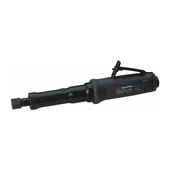
Ingersoll-Rand G2 Series Maintenance Information
Air grinder, die grinder and sander
Hide thumbs
Also See for G2 Series:
- Product information (53 pages) ,
- Maintenance information (8 pages) ,
- Product information (56 pages)

Related Manuals for Ingersoll-Rand G2 Series


Summary of Contents for Ingersoll-Rand G2 Series
- Page 1 04581245 Edition 1 April 2006 Air Grinder, Die Grinder and Sander Series G2 (Angle) Maintenance Information Save These Instructions...
- Page 2 WARNING Always wear eye protection when operating or performing maintenance on this tool. Always turn off the air supply and disconnect the air supply hose before installing, removing or adjusting any accessory on this tool, or before performing any maintenance on this tool. Note: When reading the instructions, refer to exploded diagrams in Parts Information Manuals when applicable (see under Related Documentation for form numbers).
- Page 3 Disassembly of Extension Assembly on G2E and 3. Remove the Vanes (28) from the Rotor (27). 4. Grasp the Rotor in smooth sided vise jaws with the Bevel G2L Models Pinion or Spindle Bearing Nut upward. Using a 1/2” 1. Grasp the tool mounted in the Clamp Tool (96), in soft- wrench for the Nut or a 9/16”...
- Page 4 3. Install Exhaust Seal (14) onto small end of Cylinder and Spacer. Saturate the felt with Ingersoll Rand No. 50 Oil. move it all the way down over O-Ring. Line up and seat Place the assembled Spacer, Seal Assembly trailing, protrusion on Exhaust Seal with slot in Cylinder for proper onto the threaded hub of the Rotor.
- Page 5 (39) with approximately 1 cm of Ingersoll Rand No. 68 PRESS IN UPPER ARBOR BEARING Grease and install the Coupling over the Bearing Nut. TO DIMENSION SHOWN Position the Clamp Sleeve (40) over the Coupling in the Motor Housing. 8. Insert the Spindle Bearing Nut in the assembled Extension Housing into the Arbor Coupling and thread the Extension Housing onto the Cylinder.
-
Page 6: Troubleshooting Guide
11. Thoroughly clean the internal threads of the Angle Head 2. Position the Guard Adapter Assembly (79) recessed and the threads on the Arbor Bearing Cap (56 or 75). surface leading, on the hub at the spindle end of the 12. -
Page 7: Related Documentation
Troubleshooting Guide Trouble Probable Cause Solution Excessive runout Bent Arbor. Replace the Arbor. Loose Collet Nut. Tighten the Collet Nut until snug. Worn or damaged Collet, Collet Nut or Replace the damaged component and retest. Nosepiece. Worn or damaged Upper Arbor Bearing or Replace the worn or damaged Bearing. - Page 8 www.irtools.com Ingersoll Rand © 2006 Company...
Need help?
Do you have a question about the G2 Series and is the answer not in the manual?
Questions and answers