Table of Contents
Advertisement
Advertisement
Table of Contents

Summary of Contents for ParkerBrand PPG-2800
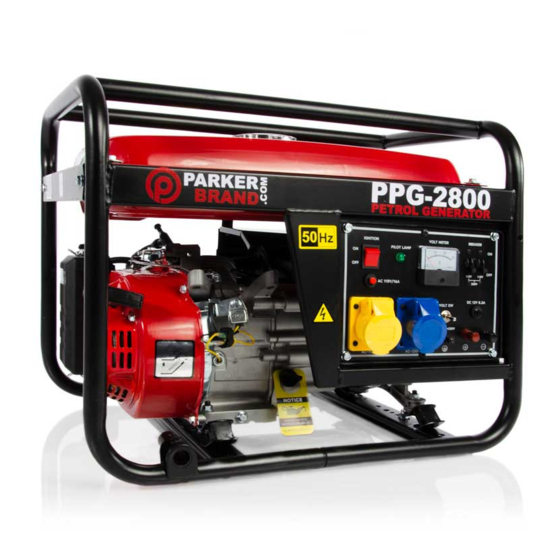
- Page 1 CLICK TO CHANGE TEXT PETROL GENERATOR PPG-2800, PPG-3750 OWNERS MANUAL...
-
Page 2: Table Of Contents
INTRODUCTION CONTENTS GENERAL SAFETY RULES ....................4 SAFETY SYMBOLS ......................... 5 PRODUCT FEATURES ......................6-9 BEFORE USING THE GENERATOR ................10-11 WHEEL ASSEMBLY (PPG-3750)..................12-15 This manual has been produced by Parker Products Ltd. and should be kept with the CHECK ENGINE OIL ...................... -
Page 3: General Safety Rules
GENERAL SAFETY RULES SAFETY SYMBOLS WORK AREA PREVENTION OF ELECTRIC SHOCK WARNING - To reduce the risk of injury, DANGER! Petroleum spirit is highly flammable. • NEVER use the generator in wet conditions unless it is well • user must read instruction manual. No smoking or naked light. -
Page 4: Product Features
PRODUCT FEATURES PRODUCT FEATURES FUEL LEVEL VOLT INDICATOR METER CHOKE LEVER FUEL TANK OIL ALARM BREAKER SWITCH CARBURETTOR COIL PLUG CAP OIL DRAIN DC 12V PLUG RESET 6.5HP ENGINE 110/230V VOLTAGE AC SOCKETS SWITCH... - Page 5 PRODUCT FEATURES PRODUCT FEATURES AIR FILTER FUEL TAP OPEN FRAME EXHAUST ENGINE DAMPERS RECOIL CONTROL PANEL ENGINE COOLING TIN...
-
Page 6: Before Using The Generator
Connect the generator to an earth point using the earth terminal (Fig 1.) Inside the box there should be. The Generator, a 110-130V Plug, a 220- 250V Plug and Spark Plug Box Spanner, If any are missing or have been damaged in transit, contact ParkerBrand immediately. BEFORE USING THE GENERATOR •... - Page 7 WHEEL KIT ASSEMBLY (WHERE SUPPLIED) WHEEL KIT ASSEMBLY (WHERE SUPPLIED) INSPECT THE WHEEL KIT AXLE ASSEMBLY NOTICE THIS WHEEL KIT IS Check the Wheel Kit is not damaged and all Slide the axle into the axle housing located on the Slide the axle all the way through the housing ensuring COMPATIBLE WITH THE components are in good working order before use.
-
Page 8: Wheel Assembly (Ppg-3750)
WHEEL KIT ASSEMBLY (WHERE SUPPLIED) WHEEL KIT ASSEMBLY (WHERE SUPPLIED) WHEEL ASSEMBLY RUBBER FEET EXTENSION ASSEMBLY Slide the wheel over the threaded end of the axle. With the wheel located on the axle place the washer, First fit the rubber feet to the rubber feet extension bar. The rubber feet extension will ensure that the generator locking washer and nut on to the thread. - Page 9 WHEEL KIT ASSEMBLY (WHERE SUPPLIED) MOVING THE GENERATOR (WHERE SUPPLIED) - OPTIONAL EXTRA HANDLE ASSEMBLY WHEEL FUNCTION HANDLE FUNCTION Line up the handle assembly with the hole at the top of Carefully thread the long bolt through the handle The wheels of the PPG-3750 are located at the engine The extendable handles are located at the exhauast end the generator frame.
-
Page 10: Check Engine Oil
CHECK ENGINE OIL LEVEL CHECK FUEL LEVEL UNSCREW OIL CAP CHECK DIPSTICK ADD OIL CHECK FUEL GAUGE REMOVE FUEL CAP ADD FUEL 'HIGH' LEVEL 'FULL' 'LOW' LEVEL 'EMPTY' 'FULL' Check the fuel level on the fuel gauge (located To add fuel, remove the fuel filler cap Add fuel to the fuel tank watching the fuel level Turn the oil filler cap anti clockwise and remove Take out the dipstick and clean with a cloth. -
Page 11: Starting The Engine
STARTING THE ENGINE STARTING THE ENGINE SET BREAKER SWITCH TURN FUEL VALVE ON SET CHOKE SWITCH ENGINE ON PULL STARTER RECOIL SET CHOKE Remove all connections from the AC sockets. Turn the fuel supply valve to the ‘ON’ position. If you are starting the generator ‘Cold’ , set the Turn the engine switch to the 'ON' position Pull the starting handle lightly until you start to Once the engine has warmed up, set the choke... -
Page 12: Ac Power
AC POWER DC POWER PRE CHECK SET BREAKER SWITCH CHARGING CAR BATTERIES DC OVER LOAD PROTECTOR Start the engine. (See pages 14-15) Set the breaker to ‘ON’ . Connect the battery charging leads to the battery. If the DC overload protector activates, wait for a few Clamp the red wire to the positive (+) terminal and the minutes and then press the reset button shown on the Make sure the appliance is turned off before... -
Page 13: Shutting Down The Generator
SHUTTING DOWN THE GENERATOR CHANGING THE ENGINE OIL DISCONNECT APPLIANCES TURN OFF ENGINE TURN OFF FUEL VALVE REMOVE OIL PLUG REPLACE OIL PLUG Unscrew and remove the oil filler cap/dipstick. Replace the oil plug and its seal ring. Fill the crankcase Disconnect all appliances connected to the Set the engine switch to ‘OFF’... -
Page 14: Draining The Carburettor
DRAIN THE CARBURETTOR REMOVE CARB DRAIN SCREW DRAIN FUEL REPLACE DRAIN SCREW THIS PAGE HAS INTENTIONALLY BEEN LEFT BLANK Place an empty container under the When the screw is removed - excess fuel will Replace drain screw. carburettor. drain from the carburettor and collect into the container. -
Page 15: Changing The Spark Plug
CHANGING THE SPARK PLUG CHECKING THE AIR FILTER REMOVE SPARK PLUG CAP REMOVE SPARK PLUG CHECK SPARK PLUG GAP REMOVE COVER REMOVE FILTER ELEMENT CLEAN AIR FILTER ELEMENT Gap 'A' Set Between 0.7mm - 0.8mm Remove the spark plug cap from the spark plug. Use the supplied spark plug spanner to remove Check the spark plug gap (a), it should be Unlock and remove the air filter cover. -
Page 16: Cleaning Fuel Valve/Draining The Fuel Tank
Place an approved petrol storage container under the fuel valve and set the fuel supply valve to ‘ON’ . The fuel in the tank will drain into the container. If this does not solve your problem, please contact the ParkerBrand customer service department 01507 499198. - Page 17 SEAL LIGHT Illustrations accurate at time of going to print. Please be aware products and parts may change design without notice. HEX. FLANGE BOLT VOLTMETER CORD SHEATH For a High Resolution copy of this exploded parts diagram please visit www.parkerbrand.com...
- Page 18 Please be aware products and parts may change design without notice. OIL DRAIN BOLT PRESSURE BOARD SPARK PLUG CRANK ASSEMBLY FLY WHEEL GUARD GOVERNER ARM RECOIL STARTER For a High Resolution copy of this exploded parts diagram please visit www.parkerbrand.com WASHER SPRING...
- Page 19 SPECIFICATIONS SPECIFICATIONS PPG-2800 TECHNICAL SPECIFICATIONS PPG-3750 TECHNICAL SPECIFICATIONS Type Petrol air cooled 4-Stroke OHV single cylinder Rated Frequency (Hz) Type Petrol air cooled 4-Stroke OHV single cylinder Rated Frequency (Hz) Displacement (cm³) Rated Voltage (V) 220 / 230 Displacement (cm³)
-
Page 20: Guarantee
Petrol Generator TÜV SÜD Product Service GmbH, Ridlerstraße 65, 80339 München, Model/Type: Germany. PPG-2800, PPG-3750 Notified body number: 0123 Manufacturing Date/Serial Number: Certificate number: N8MA 17 07 93525 026 2019 Parker Products Ltd Guarantees the product against defective material or damage for period of 12 Manufacturer’s authorised representative within the EC:... - Page 21 PPG-2800, PPG-3750 WWW.PARKERBRAND.COM Oct 2019 Rev 1.1...
Need help?
Do you have a question about the PPG-2800 and is the answer not in the manual?
Questions and answers