Table of Contents
Advertisement
Advertisement
Table of Contents

Related Manuals for Extreme Networks ExtremeWireless AP310i


Summary of Contents for Extreme Networks ExtremeWireless AP310i
- Page 1 ExtremeWireless™ AP310i/e Access Points Installation Guide 9036535-00 March 2020...
- Page 2 Copyright © 2020 Extreme Networks, Inc. All rights reserved. Legal Notice Extreme Networks, Inc. reserves the right to make changes in specifications and other information contained in this document and its website without prior notice. The reader should in all cases consult representatives of Extreme Networks to determine whether any such changes have been made.
-
Page 3: Table Of Contents
Table of Contents Preface...........................5 Text Conventions................................5 Documentation and Training..........................7 Getting Help..................................7 Subscribe to Service Notifications......................7 Providing Feedback..............................8 Product Overview........................ 9 AP310i/e Features................................9 AP310i/e Power Source............................10 AP310i/e Power Tables............................10 LED Indicators................................11 Purchase Order Information........................... 11 Install the Access Point......................13 AP310i/e Box Contents............................ - Page 4 Table of Contents Detachable Antenna Usage..........................37 Detachable Antenna Usage......................... 37 Australia Notice................................38 AU co-location MPE Statement......................... 38 Brazil Anatel Statement............................38 Hazardous Substances............................38 Supplement to Product Instructions........................39 NCC Statement................................39 CE Information................................39 Selling Countries:...............................39 All Operational Modes............................40 European Waste Electrical and Electronic Equipment (WEEE) Notice......... 40 Declaration of Conformity in Languages of the European Community..........
-
Page 5: Preface
Preface This section describes the text conventions used in this document, where you can find additional information, and how you can provide feedback to us. Text Conventions Unless otherwise noted, information in this document applies to all supported environments for the products in question. - Page 6 Text Conventions Preface Table 1: Notes and warnings (continued) Icon Notice type Alerts you to... Caution Risk of personal injury, system damage, or loss of data. Warning Risk of severe personal injury. Table 2: Text Convention Description This typeface indicates command syntax, or represents information as screen displays it appears on the screen.
-
Page 7: Documentation And Training
Data Center products Other resources, like white papers, data sheets, and case studies Extreme Networks offers product training courses, both online and in person, as well as specialized certifications. For details, visit www.extremenetworks.com/education/. Getting Help If you require assistance, contact Extreme Networks using one of the following methods: Extreme Portal Search the GTAC (Global Technical Assistance Center) knowledge base;... -
Page 8: Providing Feedback
4. Select Submit. Providing Feedback The Information Development team at Extreme Networks has made every effort to ensure the accuracy and completeness of this document. We are always striving to improve our documentation and help you work better, so we want to hear from you. We welcome all feedback, but we especially want to know about: •... -
Page 9: Product Overview
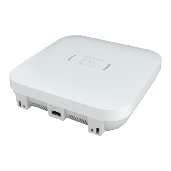
Product Overview AP310i/e Features on page 9 AP310i/e Power Source on page 10 AP310i/e Power Tables on page 10 LED Indicators on page 11 Purchase Order Information on page 11 The AP310i/e access points are indoor model 802.11ax access points. The “i” in AP310i indicates that the access point comes with internal antennas, and the “e”... -
Page 10: Ap310I/E Power Source
AP310i/e Power Source Product Overview • One safety hanger provision • One USB 2.0 type A connector • Power: PoE at 802.3at and 802.3bt (see AP310i/e Power Source for details) • Antennas: ◦ AP310i: Four Wi-Fi internal antennas and one BLE internal antenna ◦... -
Page 11: Led Indicators
Product Overview LED Indicators Table 5: AP310e power table AP310e 802.3af 802.3at and DC Radio 0 (sensor) 2.4G – 2×2 (19dBm) 2.4G – 2×2 (19dBm) 5G – 2×2 (17dBm) 5G – 2×2 (17dBm) Radio 0 (2.4G) 2×2 (19dBm) 2×2 (19dBm) Radio 0 (5G–L) 2×2 (16dBm) 2×2 (16dBm) - Page 12 Purchase Order Information Product Overview Table 7: Bracket purchase order information (continued) Part number Description 30516 WS-MBI-WALL04 bracket 37211 WS-MBI-DCFLUSH bracket Table 8: Bracket accessory purchase order information Part number Description KT-135628-01 Universal mounting kit for wireless LAN (WLAN) access points 37210 Flat metal easy-attach adapter for main mounting bracket...
-
Page 13: Install The Access Point
1. Verify the contents. 2. Visually inspect the access point, the bracket, and any other optional accessories you have ordered for physical damage. If there is any damage, contact Extreme Networks Support. 3. Read and review the safety guidelines. AP310i/e Box Contents... -
Page 14: Access Point Installation Options And Accessory Information
Access Point Installation Options and Accessory Information Install the Access Point • Two Phillips pan head wood screws • Two screw-in anchors Note All optional brackets and accessories are sold separately. Access Point Installation Options and Accessory Information The access point comes with the main mounting bracket (#37201; mounting bracket for 802.11ax indoor access points). -
Page 15: Install The Access Point On Drywall Or Wood Wall, Or To A Solid Flat Ceiling
Install the Access Point on Drywall or Wood Wall, or to a Install the Access Point Solid Flat Ceiling Table 10: Bracket and accessory usage for various installation options (continued) Mounting Wall Solid Ceilin Ceiling Junctio Beam Ceiling T-bar Notes bracket or instal flat... -
Page 16: Install The Access Point Using The Main Mounting Bracket
Install the Access Point Using the Main Mounting Bracket Install the Access Point • #37201, stainless-steel main mounting bracket with #37210, flat metal easy-attach adapter • Phillips pan head screws The best practice is to install the access point using the mounting brackets. Install the Access Point Using the Main Mounting Bracket About This Task The main mounting bracket is a stainless-steel bracket that ships with the access point. - Page 17 Install the Access Point Using the Main Mounting Install the Access Point Bracket Figure 1: Main mounting bracket Callout Description Main mounting bracket mounting holes Main mounting bracket feet 2. Insert the Phillips pan head screws into the main mounting bracket holes and attach the bracket to the wall.
- Page 18 Install the Access Point Using the Main Mounting Bracket Install the Access Point Follow this procedure to install the security torx locking screw using one of the security lock holes on the access point. Note Perform this task after the access point is attached to the main mounting bracket on a drywall or wood wall.
-
Page 19: Install The Access Point Using The Wall04 Bracket
Install the Access Point Install the Access Point Using the WALL04 Bracket Install the Access Point Using the WALL04 Bracket About This Task The optional WALL04 (#30516) bracket is used for wall installations, and ships with two Phillips pan head screws and two screw-in anchors. You must purchase the bracket separately. Note The locking tab on the WS-MBI-WALL04 bracket must be on the top side during installation. - Page 20 Install the Access Point Using the Main Mounting Bracket and Easy-Attach Adapter Install the Access Point Procedure 1. Keep the adapter to the center of the main mounting bracket, push and rotate it. Figure 3: Flat metal easy-attach adapter being attached to the main mounting bracket 2.
-
Page 21: Install The Access Point Directly On A Wall
Install the Access Point Install the Access Point Directly on a Wall 5. Place the access point onto the bracket feet and slide it down to lock it in place. Note The bracket feet must be pointing up. Install the Access Point Directly on a Wall About This Task If you do not want to use the main mounting bracket that ships with the access point, you can install the access point directly on a wall using two Phillips pan head screws. -
Page 22: Install The Access Point On A Flat T-Bar Using Main Mounting Bracket
Install the Access Point on a Flat T-bar Using Main Mounting Bracket Install the Access Point Install the Access Point on a Flat T-bar Using Main Mounting Bracket Before You Begin Ensure that the T-bar meets the following conditions before installing the main mounting bracket on a flat T-bar: •... - Page 23 Install the Access Point on a Flat T-bar Using Main Install the Access Point Mounting Bracket 2. Push and rotate the main mounting bracket on the T-bar in such a way that the center angled locking tabs of the main bracket gets attached to the T-bar. Figure 4: Install the main mounting bracket on a T-bar 3.
-
Page 24: Install The Access Point On A Flat T-Bar Using Main Mounting Bracket And Kt-135628-01 Adapter
Install the Access Point on a Flat T-bar Using Main Mounting Bracket and KT-135628-01 Adapter Install the Access Point Install the Access Point on a Flat T-bar Using Main Mounting Bracket and KT-135628-01 Adapter Before You Begin Ensure that the T-bar meets the following conditions before installing the main mounting bracket with the KT-135628-01 adapter on a T-bar: •... -
Page 25: Install The Access Point On A Flat T-Bar Using The Dcflush Bracket
Install the Access Point on a Flat T-bar Using the Install the Access Point DCFLUSH bracket Figure 5: Attach the KT-135628-01 adapter on the main mounting bracket Callout Description KT-135628-01 adapter KT-135628-01 T-bar holder KT-135628-01 adapter locking pin 3. Slide the KT-135628-01 T-bar holder onto the T-bar and replace the tiles to hold the adapter onto the T-bar. - Page 26 Install the Access Point on a Flat T-bar Using the DCFLUSH bracket Install the Access Point About This Task The WS-MBI-DCFLUSH (#37211) bracket is used on a flat T-bar when you do not want to use the main mounting bracket on it. Procedure 1.
-
Page 27: Install The Access Point On A Flat T-Bar Using The Dcmtr01 Bracket
Install the Access Point on a Flat T-bar Using the Install the Access Point DCMTR01 Bracket Install the Access Point on a Flat T-bar Using the DCMTR01 Bracket Before You Begin Ensure that the T-bar meets the following conditions before installing the DCMTR01 bracket on it: •... -
Page 28: Install The Access Point On A Junction Box Or Gang Box
Install the Access Point on a Junction Box or Gang Box Install the Access Point 5. Squeeze the bracket parts together until you hear the T-bar locking tab click into place. 6. Slide the bracket base into the rear groove of the access point. 7. - Page 29 Install the Access Point Install the Access Point on a Beam About This Task If you do not want to install the access point on a solid flat surface, you can attach it to a beam using the beam clip accessory (BRKT-000147A-01). The access point can be attached to a beam only if the beam is flat, and can support the access point in all environmental conditions.
- Page 30 Install the Access Point on a Beam Install the Access Point Procedure 1. Attach the beam clip to the main mounting bracket. Slide the beam clip accessory into the rear hinges on either side of the main mounting bracket and slightly twist it until the clip locks into place.
- Page 31 Install the Access Point Install the Access Point on a Beam 4. Tighten the beam clip accessory screw to secure the access point in place. Figure 10: Beam clip accessory attached to a beam 5. Connect the Ethernet cable RJ45 into the GE1 port. ExtremeWireless™...
-
Page 32: Antenna Configuration For External Antenna Model Access Point
Antenna Configuration for External Antenna Model Access Point Figure 11: AP310e external antennas ExtremeWireless™ AP310i/e Access Points... - Page 33 Antenna Configuration for External Antenna Model Access Point Antenna socket radio mapping information Antenna socket radio mapping information • Radio 1 (R1) - antennas 1 and 2 • Radio 2 (R2) - antennas 3 and 4 • IoT radio - BLE antenna ExtremeWireless™...
-
Page 34: Access Points Specifications
Access Points Specifications Physical specifications Item Specification Dimensions 6.4 in. × 6.4 in. × 1.7 in. (165 mm × 165 mm × 45 Weight 1.5 lbs. (0.70 kg) Housing Plastic Radios Two 802.11ax radios Console port RJ45 Environmental specifications Item Specification Operating temperature AP310i: 0°C to +50°C (32°F to +122°F) -
Page 35: Regulatory Information
Regulatory Information Safety Guidelines on page 35 MPE Statement for Mobile Devices on page 35 Federal Communications Commission (FCC) Notice on page 36 Industry Canada Notice on page 36 Detachable Antenna Usage on page 37 Australia Notice on page 38 Brazil Anatel Statement on page 38 Hazardous Substances... -
Page 36: Federal Communications Commission (Fcc) Notice
Federal Communications Commission (FCC) Notice Regulatory Information Federal Communications Commission (FCC) Notice This equipment has been tested and found to comply with the limits for a Class B digital device, pursuant to Part 15 of the FCC Rules. These limits are designed to provide reasonable protection against harmful interference in a residential installation. -
Page 37: Detachable Antenna Usage
Regulatory Information Detachable Antenna Usage Warning IC Radiation Exposure Statement: This equipment complies with ISED radiation exposure limits set forth for an uncontrolled environment. This equipment should be installed and operated with minimum distance of 28 cm between the radiator and your body. Warning Déclaration d'exposition aux radiations: Cet équipement est conforme aux limites d'exposition aux rayonnements ISED établies pour... -
Page 38: Australia Notice
Australia Notice Regulatory Information Group Brand Model number Antenna type Antenna gain (dBi) 2.4 GHz 5 GHz BLE or thread Extreme AI-DQ04360S Omni Extreme ML-2452- Panel 6.92 7.23 SEC6M4-036 / WS-AI- DQ05120 Extreme WS-AI- Panel DE07025 Extreme ML-2452- Panel 1 10.7 PNA7-01R Extreme... -
Page 39: Supplement To Product Instructions
Regulatory Information Supplement to Product Instructions Supplement to Product Instructions NCC Statement CE Information Warning CE co-location MPE Statement: This equipment complies with CE radiation exposure limits set forth for an uncontrolled environment. This equipment should be installed and operated with minimum distance of 20 cm between the radiator and your body. -
Page 40: All Operational Modes
Selling Countries: Regulatory Information Selling Countries: All Operational Modes 2.4GHz: 802.11b, 802.11g, 802.11n (HT20), 802.11n (HT40), 802.11ax (HEW20), 802.11ax (HEW40), 802.15.4 (Thread), Bluetooth (LE) 5GHz: 802.11a, 802.11n (HT20), 802.11n (HT40), 802.11ac (VHT20), 802.11ac (VHT40), 802.11ac (VHT80), 802.11ac (VHT160), 802.11ax (HEW20), 802.11ax (HEW40), 802.11ax (HEW80), 802.11ax (HEW160) The frequency and the maximum transmitted power in EU are listed below: 2412-2472MHz: 19.98 dBm 2402-2480MHz (LE): 6.23 dBm... -
Page 41: Declaration Of Conformity In Languages Of The European Community
Compliance at Green@extremenetworks.com. Declaration of Conformity in Languages of the European Community English Hereby, Extreme Networks, declares that the radio equipment type (AP310i/e) is in compliance with Directive 2014/53/EU. For full text of the EU Declaration of Conformity, please contact Extreme Regulatory Compliance at compliancerequest@extremenetworks.com... - Page 42 παρακαλούμε επικοινωνήστε με την ακραία κανονιστική συμμόρφωση στο compliancerequest@extremenetworks.com Icelandic Extreme Networks lysir her med yfir að thessi bunadur, Radio LAN device (AP310i/e), uppfyllir allar grunnkrofur, sem gerdar eru i R&TTE tilskipun ESB nr 2014/53/EU. Fyrir fullan texta í ESB yfirlýsingu um samræmi, vinsamlegast hafðu...
- Page 43 Declaration of Conformity in Languages of the Regulatory Information European Community Portuguese Extreme Networks declara que este Radio LAN device (AP310i/e) está conforme com os requisitos essenciais e outras disposições da Directiva 2014/53/EU. Para o texto integral da declaração de conformidade da UE, contacte a conformidade regulamentar extrema em compliancerequest@extremenetworks.com...
-
Page 44: Index
Index features (continued) Kensington lock 9 access points specifications LED information 9 environmental specifications 34 power source 9 physical specifications 34 radios 9 power specifications 34 reset button 9 antenna configuration 32, 33 safety hanger 9 antennas temperature 9 external antennas 9 USB 9 internal antennas 9 feedback 8 Australia notice 38 flat t-bar install DCFLUSH bracket 21 DCMTR01 bracket 21 KT-135628-01 adapter 21 beam install... - Page 45 Index main bracket install (continued) wood wall install 16 main mounting bracket on flat T-bar 22 notices 5 power source external 12V DC power supply 10 Power over Ethernet (PoE) 10 power tables AP310e power table 10 AP310i power table 10 product overview AP310e access point 9 AP310i access point 9 purchase order information bracket accessories beam clip accessory 11...
Need help?
Do you have a question about the ExtremeWireless AP310i and is the answer not in the manual?
Questions and answers