Advertisement
Quick Links
Safe Operation Practices • Assembly & Set-Up • Controls & Operation • Service • Troubleshooting
O
'
M
peratOr
s
anual
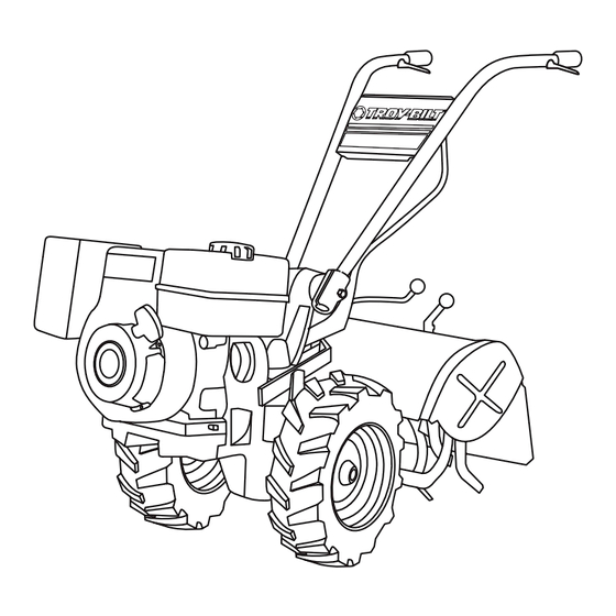
Rear-Tine Tiller — Horse/Big Red
WARNING
READ AND FOLLOW ALL SAFETY RULES AND INSTRUCTIONS IN THIS MANUAL
BEFORE ATTEMPTING TO OPERATE THIS MACHINE.
FAILURE TO COMPLY WITH THESE INSTRUCTIONS MAY RESULT IN PERSONAL INJURY.
NOTE: This Operator's Manual covers several models. Features may vary by model. Not all features in this manual are applicable to all
models and the model depicted may differ from yours.
TROY-BILT LLC, P.O. BOX 361131 CLEVELAND, OHIO 44136-0019
Form No. 769-12551A
(September 9, 2019)
Advertisement

Related Manuals for Troy-Bilt 21AE682W766


Summary of Contents for Troy-Bilt 21AE682W766
- Page 1 NOTE: This Operator’s Manual covers several models. Features may vary by model. Not all features in this manual are applicable to all models and the model depicted may differ from yours. TROY-BILT LLC, P.O. BOX 361131 CLEVELAND, OHIO 44136-0019 Form No. 769-12551A...
-
Page 2: Table Of Contents
If you have difficulty assembling this product or have any questions regarding the controls, operation, or maintenance of this machine, you can seek help from the experts. Choose from the options below: ◊ Web: www.troybilt.com ◊ Phone: (800) 828-5500 or (330) 558-7220 ◊ Mail: Troy-Bilt LLC • P.O. Box 361131 • Cleveland, OH • 44136-0019... -
Page 3: Safe Operation Practices
Important Safe Operation Practices WARNING! This symbol points out important safety instructions which, if not followed, could endanger the personal safety and/or property of yourself and others. Read and follow all instructions in this manual before attempting to operate this machine. Failure to comply with these instructions may result in personal injury. - Page 4 Notice Regarding Emissions If the machine should start making an Check bolts and screws for proper tightness unusual noise or vibration, stop the engine, at frequent intervals to keep the machine in disconnect the spark plug wire and ground safe working condition. Also, visually inspect Engines which are certified to comply with it against the engine.
-
Page 5: Assembly & Set-Up
Wheel Speed Check that you have the items listed above Lever (contact your local dealer or the Troy-Bilt Depth Figure 3-4 Technical Service Department if any items are Regulator missing or damaged). - Page 6 The lever should automatically return to the the hole in the long link bar. See Figure 3-9. Neutral position. See Figure 3-12. If not, do not use the tiller. See your local authorized dealer or call the Troy-Bilt Technical Service Clutch Department for instructions. Pawl...
- Page 7 Set-Up NOTE: If the battery is put into service after the Engine Throttle Lever and Cable date shown on the top of the battery, charge for For shipping purposes, the throttle cable, together a minimum of one hour at 6-10 amps. Refer to the Tires with the throttle lever, is wound around the engine.
-
Page 8: Controls & Operation
Controls & Operation WARNING! Never run the engine indoors or in an enclosed, poorly ventilated area. Engine exhaust contains carbon monoxide, Engine Throttle Lever an odorless and deadly gas. Avoid engine muffler and nearby areas. Temperatures in Handlebar Height these areas may exceed 150° F. Adjustment Lever NOTE: After the first two hours of operation, perform the maintenance procedures shown in the... - Page 9 Stopping the Engine and the Tiller If equipped with an electric start system, turn When the tiller moves forward, relax and let the key to START position to crank the engine the wheels power the tiller along while the To stop the wheels and tines, move the then release when the engine starts.
- Page 10 Stopping Reverse Motion At the end of a row, move the Wheels/Tines/ PTO Drive Lever to NEUTRAL position and Release the Wheels/Tines/PTO Drive Lever — the reduce the engine speed. lever automatically returns to the NEUTRAL position. Move the Tines/PTO Clutch Lever into the This stops the wheels immediately.
- Page 11 NOTE: If extra belt slack is needed to move Changing Belt From Low Range to High Range Check that the belt is fully seated in the pulley the belt, just raise the Wheels/Tines/PTO Drive grooves. Check this from both sides of the To avoid personal injury, shut off the engine, Lever up into REVERSE.
- Page 12 • When cultivating — breaking up the surface • If the garden size will not permit lengthwise • When tilling vertically, try to make the first soil around plants to help destroy weeds — and then crosswise tilling, then overlap the pass uphill as the tiller digs more deeply going uphill than it does downhill.
- Page 13 PTO Power Feature • Move the belt into LOW belt range and the • Pushing over (but not uprooting) cornstalks Wheel Speed Gear Lever to SLOW position. will often make it easier for your tiller to chop Your tiller is a self-contained PTO (Power Take-Off) As in terrace gardening, start at the top of the up the stalks.
- Page 14 Loosen the two swing-out bolts that The guide pin on the power unit will slide out If the engine is stopped, move Wheel Speed Lever connect the power transmission to the tine of the guide hole in the tine attachment See to FREEWHEEL, and manually push the tiller.
-
Page 15: Service
Service Maintenance Schedule After 2-hour Refer to Engine Before Each Use Every 10 Hours Every 25 Hours Every 30 Hours Break-In Manual Check Engine Oil Level Clean Engine Cooling System Test Operation of FWD. Interlock Safety System FWD. Interlock Safety System — Check Wire Condition/Connections Check Electrical Connections Recharge Battery... - Page 16 Figure 5-3. Do not tighten the locknut against the eccentric lever. It should be very close to, • If a serious leak is discovered, please contact but not touching the lever. your authorized dealer or the TROY-BILT Technical Service Department for service Tine Hardware advice. •...
- Page 17 Use a 3⁄8” wrench to remove the oil level check Loosen and remove the transmission dipstick Using a 3⁄4” wrench (or socket), remove the plug on the left side of the transmission on the back of the tine shield. See Figure 5-7. bolt securing the handlebar base to the top housing.
- Page 18 Adding Gear Oil to the Tine Attachment A broken or disconnected wire could let the Keep the PTO access area well-greased. See Transmission engine run without you having to press one of Figure 5-11. If the Tines/PTO Clutch Lever the Forward Interlock Levers. becomes hard to move, squirt some oil into Select the right Depth Regulator Lever setting: its access hole, and work it back and forth to...
- Page 19 Move the Wheels/Tines/PTO Drive Lever fully Move the Wheels/Tines/PTO Drive Lever Push the drive lever down if the belt needs to NEUTRAL position. The clutch roller will down to the FORWARD position. The clutch tightening. Pull the lever up if the belt needs come to rest anywhere on the face of the belt roller at the bottom of the lever should be to be loosened.
- Page 20 Checking and Adjusting the Reverse Drive System Use your left hand to hold the Wheels/Tines/ Place a 7⁄8” wrench on the head of the reverse PTO Drive Lever up in REVERSE, while briefly adjustment bolt and a 9⁄16” wrench on the jam When the Wheels/Tines/PTO Drive Lever is moved up pulling out the engine recoil starter.
- Page 21 Throttle Cable While kneeling on the right side of the tiller, Push the Wheels/Tines/PTO Drive Lever down create slack in the belt by reaching over to the into the FORWARD position. This increases The throttle lever settings are factory adjusted, left side of the pulleys and pushing in on the the distance between the upper and lower so unnecessary adjustments should not be made.
- Page 22 Reverse Disc If badly worn, they lose the ability to till deeply. Worn Mount the new tine exactly the way the old tines leave an ever-increasing gap in the middle of a tine was positioned. (The sharp edge of the Follow these steps to replace the reverse disc.
-
Page 23: Troubleshooting
Troubleshooting Problem Cause Remedy Wheels and tines do not turn 1. Mis-adjusted drive belt and/or reverse disc 1. See Maintenance & Adjustments Section 2. Loose bolt on transmission drive pulley 2. Tighten bolt 3. Worn worm gears 3. See authorized service dealer Wheels and tines turn on top 1. -
Page 24: Replacement Parts
Throttle Cable Troy-Bilt Genuine Parts can be ordered through your local authorized Troy-Bilt dealer, online at www.troybilt.com or by phone at (800) 828-5500 or (330) 558-7220. To locate your nearest authorized Troy-Bilt dealer, visit www.troybilt.com or call (800) 828-5500 or (330) 558-7220. - Page 25 Notes...
- Page 26 otes...
- Page 27 otes...
-
Page 28: Warranty
MANUFACTURER’S LIMITED WARRANTY FOR The limited warranty set forth below is given by Troy-Bilt LLC with Log splitter pumps, valves, and cylinders have a separate one- year warranty. respect to new merchandise purchased and used in the United States and/or its territories and possessions, and by MTD Products...
Need help?
Do you have a question about the 21AE682W766 and is the answer not in the manual?
Questions and answers