Trend Micro TippingPoint Series Hardware Installation And Safety Manual
N-platform
Hide thumbs
Also See for TippingPoint Series:
Table of Contents
Advertisement
Advertisement
Table of Contents

Related Manuals for Trend Micro TippingPoint Series


Summary of Contents for Trend Micro TippingPoint Series
- Page 1 N-Platform Hardware Installation and Safety Guide 5900-2851 April 2016...
- Page 2 All rights reserved. This document contains confidential information, trade secrets or both, which are the property of Trend Micro. No part of this documentation may be reproduced in any form or by any means or used to make any derivative work (such as translation, transformation, or adaptation) without written permission from Trend Micro or one of its subsidiaries.
-
Page 3: Table Of Contents
Contents About this guide............................1 Target audience............................1 Related documentation...........................1 Conventions............................1 Support information..........................3 System overview............................. 4 TippingPoint architecture........................4 Security Management System (SMS)....................5 SMS server............................5 SMS client............................6 Intrusion Prevention System devices..................... 7 IPS local clients........................... 7 Core Controller............................ - Page 4 Rack and clearance requirements....................... 14 Ventilation and location........................15 Environmental requirements.........................15 Reliable earthing...........................16 ESD requirements..........................16 Hot swapping guidelines........................16 Unpack the product..........................17 TippingPoint 660N and 1400N device overview.................19 Device overview............................19 Chassis features..........................21 Power switch........................... 21 Ports..............................21 LEDs..............................21 Model requirements..........................
- Page 5 To attach network connections......................27 Using the external ZPHA module......................27 Check LEDs............................27 Setup wizard............................28 TippingPoint 2500N, 5100N, and 6100N devices overview............... 29 Device overview............................29 Chassis features..........................31 Power switch........................... 31 Ports..............................31 LEDs..............................32 Model requirements..........................32 Power requirements........................... 33 Cabling requirements.........................
- Page 6 Power supply and fan modules......................39 N-Platform AC power supply........................39 N-Platform DC power supply........................40 N-Platform fans.............................41 Installing the power cord retention bracket..................42 Power cord retention bracket....................... 42 Installing and using the bracket......................42 Installing the bracket..........................43 Using the power cord retention bracket.................... 43 Removing the bracket..........................
-
Page 7: About This Guide
About this guide Welcome to the N-Platform Hardware Installation and Safety Guide. This section covers the following topics: • Target audience on page 1 • Related documentation on page 1 • Support information on page 3 • Target audience The intended audience includes technicians and maintenance personnel responsible for installing, configuring, and maintaining TippingPoint security systems and associated devices. - Page 8 Typefaces TippingPoint uses the following typographic conventions for structuring information: Convention Element Bold font • Key names • Text typed into a GUI element, such as into a box • GUI elements that are clicked or selected, such as menu and list items, buttons, and check boxes.
-
Page 9: Support Information
Tip: Provides helpful hints and shortcuts, such as suggestions about how to perform a task more easily or more efficiently. Support information Contact the TippingPoint Technical Assistance Center (TAC) by using any of the following options. Note: Have the following information about your product available: •... -
Page 10: System Overview
System overview The TippingPoint system is a high-speed, comprehensive security system that includes the Intrusion Prevention System (IPS), Local Security Manager (LSM), Digital Vaccine, the Security Management System Appliance, and the Core Controller. Enterprise security schemes once consisted of a conglomeration of disparate, static devices from multiple vendors. -
Page 11: Security Management System (Sms)
Security Management System (SMS) Describes the core components of the SMS. The SMS core components include: SMS Secure Server —hardware appliance for managing multiple devices • • SMS Home Page — web-based interface with links to current client software, documentation, and the Threat Management Center SMS Management Client —... -
Page 12: Sms Client
• Filter and software distribution — Monitors and maintains the distribution and import of filters, Digital Vaccine packages, and software for the TippingPoint Operating System and SMS client. The SMS client and Central Management Server can distribute these packages according to segment group settings. -
Page 13: Intrusion Prevention System Devices
The SMS dashboard provides at-a-glance monitors with launch capabilities into the targeted management applications that provide global command and control of TippingPoint. Included in the SMS dashboard display are the following items: • Entries for the top five filters triggered over the past hour in various categories •... -
Page 14: Core Controller
• Command Line Interface (CLI) — Command line interface for reviewing and modifying settings on the device. The CLI is accessible through Telnet and SSH (secure access). • LCD Panel — Several IPS TippingPoint devices provide an LCD panel to view, configure, and modify some device settings. -
Page 15: Threat Suppression Engine
and monitors the health of the active system. If the health or communications check of the active system fails, the passive SMS will be activated. The ZPHA modular device can be attached to an IPS to route traffic in the event of power loss. Smart ZPHA modules, which are wired into the device, and bypass I/O modules, which are installed directly into NX-Platform devices, perform the same function. - Page 16 • Application Protection — Defend against known and unknown exploits that target applications and operating systems: • Attack Protection filters — Detect and block traffic known to be malicious, suspicious, and to have known security implications. These filters include vulnerabilities and exploits filters. •...
-
Page 17: Hardware Safety And Compliance
Hardware safety and compliance This topic describes TippingPoint product regulatory compliance and provides safety requirements and warnings. Before installing your TippingPoint product, you must read through all preparation instructions and safety requirements. • Safety and compliance requirements on page 11 •... -
Page 18: Cautions
• This product has serviceable modules and hot-swappable power supplies. It has no other serviceable parts inside. Cautions Cautions tell you how to avoid a serious loss that stops short of physical damage such as the loss of data, time, or security. Cautions tell you what you should or should not do to avoid such losses, and the consequences of not heeding the caution. -
Page 19: Parts Warnings
Warning! When installing the product, always make the ground connection before applying power to the unit. This equipment needs to be grounded to an external ground connection. Use a green and yellow 14 AWG ground wire to connect the host to earth ground during normal use. Disconnect the ground connection only when the unit is completely powered down. -
Page 20: Rack And Clearance Requirements
flow of cooling air through the chassis. To prevent electric shock, do not open the enclosure of the product. Warning! To reduce the risk of fire, use only No. 26 AWG or larger telecommunication line cord. Warning! Risk of explosion if battery is replaced by an incorrect type. Dispose of used batteries according to the instructions. -
Page 21: Ventilation And Location
The vertical hole spacing on the rack rails must meet standard EIA-310-C requirements, which call for a one inch (2.54 cm) spacing. Ensure that you have a minimum of three inches clearance at the side of the ventilation slots. Note: Some devices have different rack and clearance requirements, or may have other mounting and installation options. -
Page 22: Reliable Earthing
Reliable earthing Ensure that an external grounding connection is available for the product. Follow these guidelines: • For AC-powered products, use only the AC power cords that have been provided with the product. Using other cords could be hazardous to your safety. •... -
Page 23: Unpack The Product
Some TippingPoint devices allow you to hot swap cards or modules. The TippingPoint has a comprehensive detection system that senses automatically when you add or remove a card or module. It then runs diagnostic and discovery routines and acknowledges the presence or absence of the card. If you remove a card or module and replace it with the same type of card or module, the system resumes operation without any operator intervention. - Page 24 7. Inspect all the equipment inside for damage. If you think any equipment might be damaged, contact your freight provider for how to lodge a damage claim. Also, contact your TippingPoint sales or field representative for instructions. Note: The shipping materials are recyclable. Please save for later use or dispose of them appropriately. N-Platform Hardware Installation and Safety Guide...
-
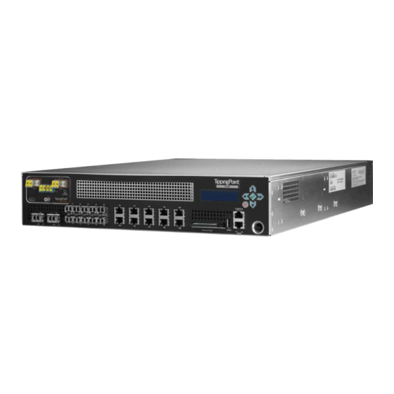
Page 25: Tippingpoint 660N And 1400N Device Overview
TippingPoint 660N and 1400N device overview This topic describes the components, chassis, requirements, and installation of the TippingPoint 660N and TippingPoint 1400N and their components. These devices are associated with the following part numbers: Model HPE part number Trend Micro part number TippingPoint 660N JC019A TPNN0020 TippingPoint 1400N JC020A TPNN0023 Prior to installation, you should also obtain the IPS Command Line Interface Reference. - Page 26 1. 1GbE Segments (Fiber) 2. 1GbE Segments (Copper) 3. LCD Screen 4. ZPHA Port 5. LCD Keypad 6. Compact Flash 7. Management Port 8. Power Button Figure 3. TippingPoint 660N/TippingPoint 1400N - back panel 1. Power Supplies 2. Power Supply Reset Button 3.
-
Page 27: Chassis Features
4. Ground Strap Mounting Chassis features Provides links to the various N-Platform chassis features. Power switch • on page 21 • Ports on page 21 • LEDs on page 21 Power switch The power switch is located on the front panel. The power switch light indicates its current status: •... -
Page 28: Model Requirements
Port Type Color Description Copper Link Green Link is active. Activity Blinking Data traffic passing. amber Fiber Link Green Link is active. Activity Amber Data traffic passing. Management Link Green Link is active. Port Activity Blinking Data traffic passing. amber Model requirements Provides links to topics that describe power and cabling requirements. -
Page 29: Cabling Requirements
Warning! This product requires short-circuit (overcurrent) protection, to be provided as part of the building installation. Install only in accordance with national and local wiring regulations. The TippingPoint 660N/TippingPoint 1400N power supply modules are hot-swappable. Refer to Power supply and fan modules on page 39 for information about hot-swapping modules. -
Page 30: Software Specifications
Specification Description Power Requirements 100-240 VAC @ 7-5 amperes, 50/60 Hertz Maximum power consumption 520W Service Provider operating requirements: 32 to 104° F (0-40° C) — Operating • Temperature -4 to 158° F (-20 to 70° C) — Storage No degradation up to 13,000 feet •... -
Page 31: Hardware Installation And Configuration
If you want to use the TippingPoint Security Management System (SMS) to manage the TippingPoint 660N/TippingPoint 1400N, the TippingPoint SMS device must be installed on your network and you must have the TippingPoint SMS client software V. 3.6+ installed on an appropriate client computer. -
Page 32: Connect The Power Supply
The TippingPoint 660N/TippingPoint 1400N ships with a slide rail kit to mount the device to the rack. Slide rail kits are also available for order from TippingPoint. Refer to the instructions in the slide rail kit for information about installing the slide rails. If you are bolting the TippingPoint 660N/TippingPoint 1400N to the rack, follow these guidelines. -
Page 33: To Attach The Management Processor Connection
• Baud rate: 115.2 Kbps • Character size: 8 bits • Parity: None • Stop Bits: One • Flow Control: None To attach the Management Processor connection Describes how to attach the management processor connection. 1. Connect one end of the Category 5 Ethernet cable to the port labeled MGMT (or 10/100 on some units) located on the front panel. -
Page 34: Setup Wizard
It then displays LEDs to show the status of each component. Refer to LEDs on page 21 for more information about the LEDs. Setup wizard After you have powered on, the TippingPoint Setup wizard is displayed on your COM port terminal. The wizard prompts you to perform basic configuration tasks and periodically input information. -
Page 35: Tippingpoint 2500N, 5100N, And 6100N Devices Overview
This topic describes the components, chassis, requirements, and installation of the TippingPoint 2500N/5100N/6100N devices and their components. These devices are associated with the following part numbers: Model HPE part number Trend Micro part number TippingPoint 2500N JC021A TippingPoint 5100N JC022A TippingPoint 6100N JC577A Prior to installation, you should also obtain the IPS Command Line Interface Reference. - Page 36 Model Supported throughput TippingPoint 5100N Up to 5 Gbps TippingPoint 6100N Up to 8 Gbps The TippingPoint 2500N/5100N/6100N chassis is rack-mountable on a 19- or 23-inch rack. 1. ZPHA Module Bay 2. LCD Screen 3. LCD Keypad 4. 10GbE Segment Ports 5. 1GbE Segments (Fiber) 6.
-
Page 37: Chassis Features
1. Power Supplies 2. Power Supply Reset Button 3. Power Cord Bracket 4. Ground Strap Mounting Chassis features Provides links to the various chassis features. • Power switch on page 31 • Ports on page 31 LEDs • on page 32 Power switch The power switch is located on the front panel. -
Page 38: Leds
The TippingPoint 2500N/5100N/6100N front panel includes the following ports: • 10 1GbE copper ports paired into 5 1GbE segments • 10 1GbE fiber ports paired into 5 1GbE segments • 1 1GbE copper management port • 1 RJ-45 console port •... -
Page 39: Power Requirements
• Power requirements on page 33 • Cabling requirements on page 33 Power requirements Describes the power requirements of the TippingPoint 2500N/5100N/6100N devices. The TippingPoint 2500N/5100N/6100N requires one input of Alternating Current (AC) that must meet the following requirements: • Voltage: 100-240VAC •... -
Page 40: Hardware And Interface Specifications
• Hardware and interface specifications on page 34 • Software specifications on page 35 Hardware and interface specifications The following table provides technical specifications for the TippingPoint 2500N/5100N/6100N. Specification Description Dimensions 2RU - 3.41 in x 16.84 in x 23.46 in (8.67 cm x 42.78 cm x 59.59 cm) Weight 32.5 lbs (14.74 kg) -
Page 41: Software Specifications
Specification Description • 1x1GbE copper management port • 1x1 RJ-45 console port • 1 interface for external ZPHA device • 1 Compact Flash drive Note: The fiber ports do not include SFP or XFP modules. Software specifications Provides software specification considerations. To connect to and configure the TippingPoint 2500N/5100N/6100N, you must have a network-connected PC that supports Internet Explorer 7 and up, Firefox 1.5+, Mozilla 1.7+, or Netscape 8.1+. -
Page 42: Determine Total Rack Space
To install your IPS you must do the following: • Determine total rack space on page 36 Attach the device to the rack • on page 36 • Connect the power supply on page 36 Determine total rack space Provides rack space information for your IPS device. Before you install the chassis, determine the total rack space that is required to install your system. -
Page 43: Attach Cables
Attach cables Describes which connections to use to access the OBE setup wizard. The TippingPoint 2500N can aggregate and redirect up to 3 Gbps of traffic. The TippingPoint 5100N can aggregate and redirect up to 5 Gbps of traffic. The TippingPoint 6100N can aggregate and redirect up to 8 Gbps of traffic. -
Page 44: Using Zpha
Note: If you are using a TippingPoint Core Controller to distribute network traffic, attach the cables to the Core Controller 1GbE segment ports. Refer to the Core Controller documentation for more information. For more information about IPS configuration and network connections, refer to the Local Security Manager User's Guide. -
Page 45: Power Supply And Fan Modules
Power supply and fan modules This topic provides links to installation instructions for power supply modules and fans. The following subjects are discussed. • N-Platform AC power supply on page 39 • N-Platform DC power supply on page 40 • N-Platform fans on page 41 Warning! This product might have more than one power supply source. -
Page 46: N-Platform Dc Power Supply
The Status LED is green when the module is powered and running normally. When the AC power supply has been securely placed in the device, use the following procedure to connect power to the AC power supply: 1. Locate the male power input on the back of the chassis. 2. -
Page 47: N-Platform Fans
2. Latch 3. Latch Locking Screw 4. Handle 5. Fan 6. Power Input Terminal Block Caution: Do not attach a ground wire to the ground screw on the DC power supply module. The ground wire must be attached to the N-Platform chassis ground terminal with a #10 screw. The ground terminal is located in the rear of the N-Platform chassis. -
Page 48: Installing The Power Cord Retention Bracket
Installing the power cord retention bracket Provides links to topics with installation instructions for the power cord retention bracket. The following subjects are discussed: • Power cord retention bracket on page 42 • Installing and using the bracket on page 42 •... -
Page 49: Installing The Bracket
Figure 8. TippingPoint 660N - back panel 1. Power Supplies 2. Power Supply Reset Button 3. Power Cord Bracket 4. Ground Strap Mounting Follow the procedures in this section to install and use the power cord retention bracket and the cable management bracket. -
Page 50: Removing The Bracket
2. Push the folded cable into the slot until the cable loop goes past the sheet metal tabs. 3. Secure the folded cable loop under the sheet metal tabs and attach the power cable to the power supply. Removing the bracket Describes how to remove a bracket. -
Page 51: Using The Lcd Panel
Using the LCD panel The LCD panel can be used to perform initial device configuration, as well as other maintenance tasks. The following subjects are discussed: • Features of the LCD keypad on page 45 • Configuring the TippingPoint IPS with the LCD panel on page 45 •... -
Page 52: Other Lcd Panel Tasks
Note: Without the system-generated super-user name and password, you cannot log in to the TippingPoint IPS device. 4. The system prompts you to enter a host name. By default, the host name is set to NCP00. You can edit the numerals but not the letters. 5. - Page 53 • HA State Query — Displays the current High Availability state and settings. • Contrast Set — Set the display contrast for the LCD panel. Backlight Set — Set the backlight level for the LCD panel. • • Eject CF — See Unmounting and ejecting the CompactFlash card on page 49.
-
Page 54: Using The External Storage Card
Using the external storage card This topic provides links to topics with external storage card information. The following topics are discussed: • About the external storage card on page 48 • External storage card commands on page 48 • Managing the N-Platform CompactFlash card in the LCD panel on page 49 About the external storage card The external storage card is used to store system logs, snapshots, and other system data. -
Page 55: Managing The N-Platform Compactflash Card In The Lcd Panel
Command Description conf t compact- Sets the device to require authentication when a flash operation- card is inserted. mode authenticate conf t compact- Sets the device to automatically mount cards when flash operation- inserted. mode auto-mount show compact-flash Displays whether the card is mounted, and if so, its model number, serial number, revision number, capacity, operation mode, and mount status. -
Page 56: Inserting A Compactflash Card
Inserting a CompactFlash card When you insert a CompactFlash card, the LCD display indicates when the card has been successfully mounted on the device. If the device has been set to require authentication for CompactFlash cards, you must complete the mounting process manually using the CLI compact-flash mount command. -
Page 57: Connector And Pinout Specifications
Connector and pinout specifications This topic provides links to topics with connector and pinout information for the IPS. This topic contains the following information: • RJ-45 (COM) console on page 51 • RJ-45 Ethernet connectors on page 52 • Pluggable transceivers on page 53 RJ-45 (COM) console Describes and provides an image of the RJ-45 connector. -
Page 58: Rj-45 Ethernet Connectors
Pin number Signal name Clear to Send (CTS) RJ-45 Ethernet connectors Describes how to use the RJ-45 connector under different operating conditions. Use the following pinout information when your RJ-45 device is operating in 10Mbps/100Mbps mode. Pin number Signal name Transmit positive (Tx+) Transmit negative (Tx-) Receive positive (Rx+) -
Page 59: Pluggable Transceivers
Pin number Signal name Twisted Pair 1 negative (TP1-) Twisted Pair 2 positive (TP2+) Twisted Pair 3 positive (TP3+) Twisted Pair 3 negative (TP3-) Twisted Pair 2 negative (TP2-) Twisted Pair 4 positive (TP4+) Twisted Pair 4 negative (TP4-) Pluggable transceivers The IPS can also have pluggable transceivers.
Need help?
Do you have a question about the TippingPoint Series and is the answer not in the manual?
Questions and answers