Table of Contents
Advertisement
Advertisement
Table of Contents

Related Manuals for ADEEPT Ultimate Kit for Arduino MEGA 2560


Summary of Contents for ADEEPT Ultimate Kit for Arduino MEGA 2560
- Page 2 Preface Adeept is a technical service team of open source software and hardware. Dedicated to applying the Internet and the latest industrial technology in open source area, we strive to provide best hardware support and software service for general makers and electronic enthusiasts around the world. We aim to create infinite possibilities with sharing.
- Page 3 Component List...
-
Page 10: Table Of Contents
Content About Arduino .......................... - 1 - Lesson 1 Blinking LED ......................- 2 - Lesson 2 Active Buzzer ......................- 7 - Lesson 3 Controlling an LED with a button ..............- 11 - Lesson 4 Controlling Relay ....................- 16 - Lesson 5 Serial Port ...................... - Page 11 Lesson 20 3-axis Accelerometer—ADXL345 ..............- 72 - Lesson 21 4x4 matrix keyboard ..................- 78 - Lesson 22 Controlling DC motor..................- 82 - Lesson 23 Joy stick ......................- 88 - Lesson 24 Tilt Switch ......................- 91 - Lesson 25 Dot-matrix display ...................
-
Page 12: About Arduino
About Arduino What is Arduino? Arduino is an open-source electronics platform based on easy-to-use hardware and software. It's intended for anyone making interactive projects. ARDUINO BOARD Arduino senses the environment by receiving inputs from many sensors, and affects its surroundings by controlling lights, motors, and other actuators. ARDUINO SOFTWARE You can tell your Arduino what to do by writing code in the Arduino programming language and using the Arduino development environment. -
Page 13: Lesson 1 Blinking Led
Lesson 1 Blinking LED Overview In this tutorial, we will start the journey of learning Arduino MEGA 2560. In the first lesson, we will learn how to make a LED blinking. Requirement - 1* Arduino MEGA 2560 - 1* USB Cable - 1* 220Ω... - Page 14 2. What is the resistor? The main function of the resistor is to limit current. In the circuit, the character ‘R’ represents resistor, and the unit of resistor is ohm(Ω). The band resistor is used in this experiment. A band resistor is one whose surface is coated with some particular color through which the resistance can be identified directly.
- Page 15 3. Key functions: ● setup() The setup() function is called when a sketch starts. Use it to initialize variables, pin modes, start using libraries, etc. The setup function will only run once, after each powerup or reset of the Arduino board. ●loop() After creating a setup() function, which initializes and sets the initial values, the loop() function does precisely what its name suggests, and loops...
- Page 16 2. Program /*********************************************************** File name: 01_blinkingLed.ino Description: Lit LED, let LED blinks. Website: www.adeept.com E-mail: support@adeept.com Author: Tom Date: 2015/12/27 ***********************************************************/ ledPin=8; //definition digital 8 pins as pin to control the LED void setup() pinMode(ledPin,OUTPUT); //Set the digital 8 port mode, OUTPUT:...
- Page 17 - 6 -...
-
Page 18: Lesson 2 Active Buzzer
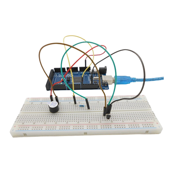
Lesson 2 Active Buzzer Overview In this lesson, we will learn how to program the Arduino to make an active buzzer sound. Requirement - 1* Arduino MEGA 2560 - 1* USB cable - 1* Active buzzer - 1* 1 kΩ Resistor - 1* NPN Transistor (S8050) - 1* Breadboard - Several Jumper Wires... - Page 19 A slightly larger current is needed to make a buzzer sound. However, the output current of Arduino’s GPIO is weak, so we need a transistor to drive the buzzer. The main function of transistor is blowing up the voltage or current. The transistor can also be used to control the circuit conduction or deadline.
- Page 20 Figure 2: Set the Arduino GPIO as low level, the transistor S8550 will conduct, and the buzzer will sound; set the Arduino GPIO as a high level, the transistor S8550 will cut off, then the buzzer will stop. Procedures 1. Build the circuit 2.
- Page 21 Summary By learning this lesson, we have mastered the basic principle of the buzzer and the transistor. We also learned how to program the Arduino and then control the buzzer. I hope you can use what you have learned in this lesson to do some interesting things.
-
Page 22: Lesson 3 Controlling An Led With A Button
Lesson 3 Controlling an LED with a button Overview In this lesson, we will learn how to detect the state of a button, and then toggle the state of LED based on the state of the button. Requirement - 1* Arduino MEGA 2560 - 1* USB Cable - 1* Button - 1* LED... - Page 23 The button jitter must be happen in the process of using. The jitter waveform is as the flowing picture: Each time you press the button, the Arduino will think you have pressed the button many times due to the jitter of the button. We must to deal with the jitter of buttons before we use the button.
- Page 24 may be implemented in hardware as a distinct system with control lines, or they may be integrated into the memory subsystem. 3. Key functions: ●attachInterrupt(interrupt, ISR, mode) Specifies a named Interrupt Service Routine (ISR) to call when an interrupt occurs. Replaces any previous function that was attached to the interrupt. Most Arduino boards have two external interrupts: numbers 0 (on digital pin 2) and 1 (on digital pin 3).
- Page 25 Pauses the program for the amount of time (in microseconds) specified as parameter. There are a thousand microseconds in a millisecond, and a million microseconds in a second. Currently, the largest value that will produce an accurate delay is 16383. This could change in future Arduino releases.
- Page 26 Summary Through this lesson, you should have learned how to use the Arduino MEGA 2560 detects an external button state, and then toggle the state of LED relying on the state of the button detected before. - 15 -...
-
Page 27: Lesson 4 Controlling Relay
Lesson 4 Controlling Relay Overview In this lesson, we will learn how to control a relay to cut off or connect a circuit. Requirement - 1* Arduino MEGA 2560 - 1* USB Cable - 1* NPN Transistor (S8050) - 1* 1K Resistor - 1* 1N4001 Diode - 1* 220Ω... - Page 28 Procedures 1. Build the circuit 2. Program 3. Compile the program and upload to Arduino MEGA 2560 board When the set of contacts was closed, the LED will be lit up; when the set of contacts was broke, the LED will go out. - 17 -...
- Page 29 Summary By learning this lesson, you have already known the basic principle of the relay, and you can also use the relay to do some creative applications. - 18 -...
-
Page 30: Lesson 5 Serial Port
Lesson 5 Serial Port Overview In this lesson, we will program the Arduino MEGA 2560 to achieve function of send and receive data through the serial port. The Arduino receiving data which send from PC, and then controlling an LED according to the received data, then return the state of LED to the PC's serial port monitor. - Page 31 communicating with the computer, use one of these rates: 300, 1200, 2400, 4800, 9600, 14400, 19200, 28800, 38400, 57600, or 115200. You can, however, specify other rates - for example, to communicate over pins 0 and 1 with a component that requires a particular baud rate. Syntax Serial.begin(speed) Parameters...
- Page 32 Serial.print(val, format) Parameters val: the value to print - any data type format: specifies the number base (for integral data types) or number of decimal places (for floating point types) Returns byte print() will return the number of bytes written, though reading that number is optional ●println() Prints data to the serial port as human-readable ASCII text followed by a...
- Page 33 2. Program 3. Compile the program and upload to Arduino MEGA 2560 board Open the port monitor, and then select the appropriate baud rate according to the program. Now, if you send a character‘1’or‘0’on the serial monitor, the state of LED will be lit or gone out.
- Page 34 Summary Through this lesson, you should have understood that the computer can send data to Arduino MEGA 2560 via the serial port, and then control the state of LED. I hope you can use your head to make more interesting things based on this lesson.
-
Page 35: Lesson 6 Led Flowing Lights
Lesson 6 LED Flowing Lights Overview In the first class, we have learned how to make an LED blink by programming the Arduino. Today, we will use the Arduino to control 8 LEDs, so that 8 LEDs showing the result of flowing. Requirement - 1* Arduino MEGA 2560 - 1* USB Cable... - Page 36 The initialization happens first and exactly once. Each time through the loop, the condition is tested; if it's true, the statement block, and the increment is executed, then the condition is tested again. When the condition becomes false, the loop ends. Procedures 1.
- Page 37 Now, you should see 8 LEDs are lit in sequence from the right green one to the left, next from the left to the right one. And then repeat the above phenomenon. Summary Through this simple and fun experiment, we have learned more skilled programming about the Arduino.
-
Page 38: Lesson 7 Led Bar Graph Display
Lesson 7 LED bar graph display Overview In this lesson, we will learn how to control a LED bar graph by programming the Arduino. Requirement - 1* Arduino MEGA 2560 - 1* USB Cable - 1* 10KΩ Potentiometer - 10* 220Ω Resistor - 1* LED Bar Graph - 1* Breadboard - Several Jumper Wires... - Page 39 The internal schematic diagram for the LED bar graph is shown below: A potentiometer, informally a pot, is a three-terminal resistor with a sliding or rotating contact that forms an adjustable voltage divider. If only two terminals are used, one end and the wiper, it acts as a variable resistor or rheostat. Procedures 1.
- Page 40 2. Program 3. Compile the program and upload to Arduino MEGA 2560 board Now, when you turn the knob of the potentiometer, you will see that the number of LED in the LED bar graph will be changed. - 29 -...
- Page 41 - 30 -...
-
Page 42: Lesson 8 Breathing Led
Lesson 8 Breathing LED Overview In this lesson, we will learn how to program the Arduino to generate PWM signal. And use the PWM square-wave signal control an LED gradually becomes brighter and then gradually becomes dark like the animal’s breathing. - Page 43 Key function: ●analogWrite() Writes an analog value (PWM wave) to a pin. Can be used to light an LED at varying brightnesses or drive a motor at various speeds. After a call to analogWrite(), the pin will generate a steady square wave of the specified duty cycle until the next call to analogWrite() (or a call to digitalRead() or digitalWrite() on the same pin).
- Page 44 2. Program 3. Compile the program and upload to Arduino MEGA 2560 board. Now, you should see the LED gradually from dark to brighter, and then from brighter to dark, continuing to repeat the process, its rhythm like the animal's breathing.
- Page 45 Summary By learning this lesson, I believe that you have understood the basic principles of the PWM, and mastered the PWM programming on the Arduino platform. - 34 -...
-
Page 46: Lesson 9 Controlling A Rgb Led By Pwm
Lesson 9 Controlling a RGB LED by PWM Overview In this lesson, we will program the Arduino for RGB LED control, and make RGB LED emits a various of colors of light. Requirement - 1* Arduino MEGA 2560 - 1* USB Cable - 1* RGB LED - 3* 220Ω... - Page 47 Procedures 1. Build the circuit 2. Program 3. Compile the program and upload to Arduino MEGA 2560 board Now, you can see the RGB LED emitting red, green, blue, yellow, white and purple light, then the RGB LED will be off, each state continues 1s, after repeating the above procedure.
- Page 48 Summary By learning this lesson, I believe you have already known the principle and the programming of RGB LED. I hope you can use your imagination to achieve even more cool ideas based on this lesson. - 37 -...
-
Page 49: Lesson 10 Play The Music
Lesson 10 Play the Music Overview In this lesson, we will program the Arduino to control a passive buzzer, and then make the passive buzzer play music. Requirement - 1* Arduino MEGA 2560 - 1* USB Cable - 1* NPN Transistor (8050) - 1* 1KΩ... - Page 50 different pin, the call to tone() will have no effect. If the tone is playing on the same pin, the call will set its frequency. Use of the tone() function will interfere with PWM output on pins 3 and 11 (on boards other than the Mega).
- Page 51 Procedures 1. Build the circuit 2. Program 3. Compile the program and upload to Arduino MEGA 2560 board Now, you can hear the music of passive buzzer with blinking an LED. - 40 -...
-
Page 52: Lesson 11 Lcd1602 Display
Overview In this lesson, we will learn how to use a character display device—LCD1602 on the Arduino platform. First, we make the LCD1602 display a string "Hello Geeks!" scrolling,then display “Adeept” and “www.adeept.com” static. Requirement - 1* Arduino MEGA 2560... - Page 53 The 4-bit mode requires seven I/O pins from the Arduino, while the 8-bit mode requires 11 pins. For displaying text on the screen, you can do most everything in 4-bit mode, so example shows how to control a 2x16 LCD in 4-bit mode. A potentiometer , informally a pot, is a three-terminal resistor with a sliding or rotating contact that forms an adjustable voltage divider.
- Page 54 Syntax lcd.print(data) lcd.print(data, BASE) Parameters lcd: a variable of type LiquidCrystal data: the data to print (char, byte, int, long, or string) BASE (optional): the base in which to print numbers: BIN for binary (base 2), DEC for decimal (base 10), OCT for octal (base 8), HEX for hexadecimal (base 16).
- Page 55 2. Program 3. Compile the program and upload to Arduino MEGA 2560 board Now, you can see the string "Hello Geeks!" is shown on the LCD1602 scrolling, and then the string "Adeept" and "www.adeept.com" is displayed on the LCD1602 static. Summary I believe that you have already mastered the driver of LCD1602 through this lesson.
-
Page 56: Lesson 12 A Simple Voltmeter
Lesson 12 A Simple Voltmeter Overview In this lesson, we will make a simple voltmeter with Arduino MEGA 2560 and LCD1602, the range of this voltmeter is 0~5V. Then, we will measure the voltage of the potentiometer’s adjustment end with the simple voltmeter and display it on the LCD1602. - Page 57 opposite direction, there are 5 volts going to the pin and the input value is 1023. In between, analogRead( ) returns a number between 0 and 1023 that is proportional to the amount of voltage being applied to the pin. Key functions: ●...
- Page 58 2. Program 3. Compile the program and upload to Arduino MEGA 2560 board. Now, when you turning the shaft of the potentiometer, you will see the voltage displayed on the LCD1602 will be changed. Summary The substance of voltmeter is reading analog voltage which input to ADC inside. Through this course, I believe that you have mastered how to read analog value and how to make a simple voltmeter with Arduino.
-
Page 59: Lesson 13 7-Segment Display
Lesson 13 7-segment display Overview In this lesson, we will program the Arduino to achieve the controlling of segment display. Requirement - 1* Arduino MEGA 2560 - 1* USB Cable - 1* 220Ω Resistor - 1* 7-segment Display - 1* Breadboard - Several Jumper Wires Principle The seven-segment display is a form of electronic display device for displaying... - Page 60 When using a common anode LED, the common anode should to be connected to the power supply (VCC); when using a common cathode LED, the common cathode should be connected to the ground (GND). Each segment of a segment display is composed of LED, so a resistor is needed for protecting the LED.
- Page 61 2. Program 3. Compile the program and upload to Arduino MEGA 2560 board Now, you should see the number 0~9 are displayed on the segment display. - 50 -...
- Page 62 Summary Through this lesson, we have learned the principle and programming of segment display. I hope you can combine the former course to modify the code we provided in this lesson to achieve cooler originality. - 51 -...
-
Page 63: Lesson 14 A Simple Counter
Lesson 14 A simple counter Overview In this lesson, we will program the Arduino MEGA 2560 to make a simple counter. Requirement - 1* Arduino MEGA 2560 - 1* USB Cable - 1* 4-digit 7-segment Display - 8* 220Ω Resistor - 2* Button - 1* Breadboard - Several Jumper Wires... - Page 64 The pin number is showing below: Procedures 1. Build the circuit - 53 -...
- Page 65 2. Program 3. Compile the program and upload to Arduino MEGA 2560 board Now, when you press one of the two buttons, the value displayed on the 4-digit 7-segment display will be changed. Summary By learning this lesson, you'll find that it is so easy to make a simple counter. - 54 -...
-
Page 66: Lesson 15 Controlling Servo Motor
Lesson 15 Controlling Servo motor Overview In this lesson, we will introduce a new electronic device (Servo) to you, and tell you how to control it with the Arduino MEGA 2560. Requirement - 1* Arduino MEGA 2560 - 1* USB Cable - 1* Servo - Several Jumper Wires Principle... - Page 67 servo.attach(pin, min, max) Parameters servo: a variable of type Servo pin: the number of the pin that the servo is attached to min (optional): the pulse width, in microseconds, corresponding to the minimum (0-degree) angle on the servo (defaults to 544) max (optional): the pulse width, in microseconds, corresponding to the maximum (180-degree) angle on the servo (defaults to 2400) Procedures...
- Page 68 Summary By learning this lesson, you should have known that the Arduino provided a servo library to control a servo. By using the servo library, you can easily control a servo. Just enjoy your imagination and make some interesting applications. - 57 -...
-
Page 69: Lesson 16 Using A Thermistor To Measure The Temperature
Lesson 16 Using a thermistor to measure the temperature Overview In this lesson, we will learn how to use a thermistor to collect temperature by programming Arduino. information which thermistor collects temperature is displayed on the LCD1602. Requirement - 1* Arduino MEGA 2560 - 1* USB Cable - 1* LCD1602 - 1* 10KΩ... - Page 70 : The Kelvin temperature that you want to measure. : At the condition of room temperature 25 ℃ (298.15K), the standard resistance of MF52 thermistor is 10K; Kelvin temperature = 273.15 (absolute temperature) + degrees Celsius; After transforming the above equation, we can get to the following formula: Procedures 1.
- Page 71 Summary By learning this lesson, I believe you have learned to use a thermistor to measure temperature. Next, you can use a thermistor to produce some interesting applications. - 60 -...
-
Page 72: Lesson 17 Ir Remoter Controller
Lesson 17 IR Remoter Controller Overview In this lesson, we will learn how to use an IR receiver to receive the remote controller signal. Requirement - 1* Arduino MEGA 2560 - 1* USB Cable - 1* IR Receiver HX1838 - 1* Remote Controller - 1* Breadboard - Several Jumper Wires Principle... - Page 73 In this experiment, we program the Arduino to receive the infrared signal, and then send the received data to the serial monitor. In the program, we used the Arduino-IRremote-master library (We provided). Note: Before using this library, you have to delete the RobotIRremote directory in your Arduino IDE directory, and delete the...
- Page 74 2. Program 3. Compile the program and upload to Arduino MEGA 2560 board Now, when you click one of the buttons on the remote controller, you will see the button number of the remote controller is displayed on the serial monitor.
- Page 75 Summary By learning this lesson, I believe you have mastered the basic principle of the infrared remote controlling. - 64 -...
-
Page 76: Lesson 18 Temperature & Humidity Sensor Dht-11
Lesson 18 Temperature & humidity sensor DHT-11 Overview In this lesson, we will learn how to use DHT-11 to collect temperature and humidity by programming Arduino. Requirement - 1* Arduino MEGA 2560 - 1* USB Cable - 1* LCD1602 - 1* 10KΩ Potentiometer - 1* DHT-11 Temperature and Humidity Sensor - 1* Breadboard - Several Jumper Wires... - Page 77 ‘-’: GND (0V) ‘S’: data pin Procedures 1. Build the circuit 2. Program /*********************************************************** File name: 18_DHT11.ino Description: you can see the temperature and humidity data displayed on the LCD1602. Website: www.adeept.com E-mail: support@adeept.com Author: Tom Date: 2015/12/27 - 66 -...
- Page 78 ***********************************************************/ #include <dht11.h> #include <LiquidCrystal.h> dht11 DHT11; #define DHT11PIN 2 LiquidCrystal lcd(4, 6, 10, 11, 12, 13);// Define the connection LCD pin void setup() lcd.begin(16, 2); //set up the LCD's number of columns and rows: lcd.clear(); //Clears the LCD screen and positions the cursor in the upper-left corner delay(1000);...
- Page 79 Summary By learning this lesson, I believe that you should be able to measure the room’s temperature and humidity. I hope you can make a simple smart home system based on this and the previous lessons. - 68 -...
-
Page 80: Lesson 19 Ultrasonic Distance Sensor
Lesson 19 Ultrasonic distance sensor Overview In this lesson, we will learn how to measure the distance by the ultrasonic distance sensor. Requirement - 1* Arduino MEGA 2560 - 1* USB Cable - 1* Ultrasonic Distance Sensor - 1* LCD1602 - 1* 10KΩ... - Page 81 Procedures 1. Build the circuit 2. Program 3. Compile the program and upload to Arduino MEGA 2560 board Now, when you try to change the distance between the ultrasonic module and the obstacles, you will find the distance value displayed on the LCD1602 will be changed.
- Page 82 - 71 -...
-
Page 83: Lesson 20 3-Axis Accelerometer-Adxl345
Lesson 20 3-axis Accelerometer—ADXL345 Overview In this lesson, we will learn how to use ADXL345 to collect acceleration by programming Arduino MEGA 2560, and then display the data that ADXL345 collects on the LCD1602. Requirement - 1* Arduino MEGA 2560 - 1* USB Cable - 1* LCD1602 - 1* 10KΩ... - Page 84 Initiate the Wire library and join the I2C bus as a master or slave. This should normally be called only once. Parameters address: the 7-bit slave address (optional); if not specified, join the bus as a master. Returns None ●Wire.beginTransmission(address) Begin a transmission to the I2C slave device with the given address.
- Page 85 the I2C bus. If false, endTransmission() sends a restart message after transmission. The bus will not be released, which prevents another master device from transmitting between messages. This allows one master device to send multiple transmissions while in control. The default value is true. Syntax Wire.endTransmission() Wire.endTransmission(stop)
- Page 86 bus. false will continually send a restart after the request, keeping the connection active. Returns byte : the number of bytes returned from the slave device ●Wire.available() Returns the number of bytes available for retrieval with read(). This should be called on a master device after a call to requestFrom() or on a slave inside the onReceive() handler.
- Page 87 2. Program 3. Compile the program and upload to Arduino MEGA 2560 board Now, you can see the acceleration data which ADXL345 collected displayed on the LCD1602. - 76 -...
- Page 88 Summary By learning this lesson, I believe that you have learned the usage of the ADXL345 to collect acceleration data. Next, you can use ADXL345 to make some interesting applications. - 77 -...
-
Page 89: Lesson 21 4X4 Matrix Keyboard
Lesson 21 4x4 matrix keyboard Overview In this lesson, we will learn how to use the matrix keyboard. Requirement - 1* Arduino MEGA 2560 - 1* USB Cable - 1* 4x4 Matrix Keyboard - 1* Breadboard - Several Jumper Wires Principle In order to save the resources of the microcontroller port, we usually connect the buttons in a matrix in an actual project. - Page 90 In this tutorial, we use the ‘Keypad’ function library. Before programming, please install the library. Procedures 1. Build the circuit 2. Program 3. Compile the program and upload to Arduino MEGA 2560 board Now, when you click one of the button on the 4x4 matrix keyboard, you will see the corresponding key value will be displayed on the serial monitor.
- Page 91 - 80 -...
- Page 92 - 81 -...
-
Page 93: Lesson 22 Controlling Dc Motor
Lesson 22 Controlling DC motor Overview In this comprehensive experiment, we will learn how to control the state of DC motor with Arduino, and the state will be displayed through the LED at the same time. The state of DC motor includes its forward, reverse, acceleration, deceleration and stop. - Page 94 OA, OB: These are used to connect the DC motor. VCC: Power supply (+5V) GND: The cathode of the power supply (Ground). IA, IB: The input terminal of drive signal. 2. DC motor A DC motor is any of a class of electrical machines that converts direct current electrical power into mechanical power.
- Page 95 DC motors were the first type widely used, since they could be powered from existing direct-current lighting power distribution systems. A DC motor's speed can be controlled over a wide range, using either a variable supply voltage or by changing the strength of current in its field windings. Small DC motors are used in tools, toys, and appliances.
- Page 96 break; default: // if nothing else matches, do the default // default is optional Syntax switch (var) { case label: // statements break; case label: // statements break; default: // statements Parameters var: the variable whose value to compare to the various cases label: a value to compare the variable to Procedures 1.
- Page 97 2. Program 3. Compile the program and upload to Arduino MEGA 2560 board Press the btn1 button to stop or run the DC motor; press the btn2 button to forward or reverse the DC motor; Press the btn3 button to accelerate the DC motor;...
- Page 98 Summary I think you must have grasped the basic theory and programming of the DC motor after studying this experiment. You not only can forward and reverse it, but also can regulate its speed. Besides, you can do some interesting applications with the combination of this course and your prior knowledge.
-
Page 99: Lesson 23 Joy Stick
Lesson 23 Joy stick Overview In this lesson, we will learn the usage of joy stick. We program the Arduino to detect the state of joy stick, and display the information on an LCD1602. Requirement - 1* Arduino MEGA 2560 - 1* USB Cable - 1* LCD1602 - 1* 10KΩ... - Page 100 push-buttons whose state can also be read by the computer. A popular variation of the joystick used on modern video game consoles is the analog stick. Joysticks are also used for controlling machines such as cranes, trucks, underwater unmanned vehicles, wheelchairs, surveillance cameras, and zero turning radius lawn mowers.
- Page 101 - 90 -...
-
Page 102: Lesson 24 Tilt Switch
Lesson 24 Tilt Switch Overview In this lesson, we will learn how to use the tilt switch and change the state of an LED by changing the angle of tilt switch. Requirement - 1* Arduino MEGA 2560 - 1* USB Cable - 1* Tilt Switch - 1* LED - 1* 220Ω... - Page 103 2. Program /*********************************************************** File name: 24_tiltSwitch.ino Description: Tilt switches to control the LED light on or off Website: www.adeept.com E-mail: support@adeept.com Author: Tom Date: 2015/12/27 ***********************************************************/ ledpin=11; //definition digital 11 pins as pin to control the //LED tiltSwitchpin=7; //Set the digital 7 to tilt switch interface val;...
- Page 104 Summary In this lesson, we have learned the principle and application of the tilt switch. Tilt switch is a very simple electronic component, but simple device can often make something interesting. - 93 -...
-
Page 105: Lesson 25 Dot-Matrix Display
Lesson 25 Dot-matrix display Overview In this lesson, we will program to control a 8*8 dot-matrix to realize the display of graphical and digital we want. Requirement - 1* Arduino MEGA 2560 - 1* USB Cable - 1* 8*8 Dot-matrix - 2* 74HC595 - 1* Breadboard - Several Jumper Wires... - Page 106 A 8*8 dot-matrix display consists of 64 LEDs, and each LED is placed at the intersection of the lines and columns. When the corresponding row is set as high level and the column is set as low level, then the LED will be lit. A certain drive current is required for the dot-matrix display.
- Page 107 The flowing is the function of each pin: DS: Serial data input Q0-Q7: 8-bit parallel data output Q7’: Series data output pin, always connected to DS pin of the next 74HC595 OE: Output enable pin, effective at low level, connected to the ground directly MR: Reset pin, effective at low level, directly connected to 5V high level in practical applications SH_CP: Shift register clock input...
- Page 108 (Make sure that the circuit connection is correct and then power, otherwise it may cause the chips to burn.) 2. Program 3. Compile the program and upload to Arduino MEGA 2560 board Now, you can see a rolling “Adeept” should be displayed on the dot-matrix display. - 97 -...
- Page 109 Summary In this experiment, we have not only learned how to operate a dot-matrix display to display numbers and letters, but also learned the basic usage of 74HC595, then you can try operating the dot-matrix display to show other images. - 98 -...
-
Page 110: Lesson 26 Controlling Stepper Motor
Lesson 26 Controlling Stepper Motor Overview In this lesson, we will learn how to control a stepper motor. Requirement - 1* Arduino MEGA 2560 - 1* USB Cable - 1* Stepper Motor - 1* ULN2003 Driver Board - Several Jumper Wires Principle 1. - Page 111 below. There are four LEDs on the top. The white booth in the middle is connected to the stepper motor. The bottom is four pins used to connect with Arduino digital pins. When a pin is high, the corresponding LED will light up. The black jump hat on the right is power source input end.
- Page 112 2. Program 3. Compile the program and upload to Arduino MEGA 2560 board Now, the stepper motor can run fast in a clockwise circle, next the stepper motor can run slow in a counterclockwise circle. - 101 -...
-
Page 113: Lesson 27 Photoresistor
Lesson 27 Photoresistor Overview In this lesson, we will learn how to measure the light intensity by photoresistor and make the measurement result displayed on the LCD1602. Requirement - 1* Arduino MEGA 2560 - 1* USB Cable - 1* LCD1602 - 1* Photoresistor - 1* 10KΩ... - Page 114 With the increase of the light intensity, the resistance of photoresistor will be decreased. The voltage of GPIO port in the above figure will become high. Procedures 1. Build the circuit 2. Program 3. Compile the program and upload to Arduino MEGA 2560 board Now, when you try to block the light towards the photoresistor, you will find that the value displayed on the LCD1602 will be reduced.
- Page 115 Summary By learning this lesson, we have learned how to detect surrounding light intensity with the photoresistor. You can play your own wisdom, and make more originality based on this experiment and the former experiment. - 104 -...
-
Page 116: Lesson 28 Automatically Tracking Light Source
Lesson 28 Automatically Tracking Light Source Overview In this lesson, we will make a light tracking system based on a servo and a photoresistor. Requirement - 1* Arduino MEGA 2560 - 1* USB Cable - 1* Servo - 1* Photoresistor - 1* 10KΩ... - Page 117 2. Program 3. Compile the program and upload to Arduino MEGA 2560 board - 106 -...
-
Page 118: Lesson 29 Frequency Meter
Lesson 29 Frequency meter Overview In this lesson, we will make a simple frequency meter with the Arduino MEGA 2560. We will acquire the frequency of square wave which is generated by 555 timer, and then send the result to serial monitor through USB port. Requirement - 1* Arduino MEGA 2560 - 1* USB Cable... - Page 119 Pin 6 is the THRESHOLD for the input of upper comparator; Pin 2 is TRIGGER for the input of lower comparator; Pin 3 is the OUTPUT having two states of 0 and 1 decided by the input electrical level; Pin 7, the DISCHARGE which has two states of suspension and ground connection also decided by input, is the output of the internal discharge tube;...
- Page 120 pulseIn(pin, value, timeout) Parameters pin: the number of the pin on which you want to read the pulse. (int) value: type of pulse to read: either HIGH or LOW. (int) timeout (optional): the number of microseconds to wait for the pulse to start; default is one second (unsigned long) Returns the length of the pulse (in microseconds) or 0 if no pulse started before the...
- Page 121 - 110 -...
- Page 122 Summary By learning this lesson, I believe that you have mastered the principle of timer and you can make a simple frequency meter by yourself. You can display the value of square frequency to a LCD1602 by modifying the code we provided. - 111 -...
-
Page 123: Lesson 30 Intrusion Detection Based On The Pir
Lesson 30 Intrusion Detection based on the Overview In this lesson, we will learn how to use Passive Infrared (PIR) sensor to detect the movement nearby. Requirement - 1* Arduino MEGA 2560 - 1* USB Cable - 1* PIR Movement Sensor - 1* 220Ω... - Page 124 Procedures 1. Build the circuit 2. Program 3. Compile the program and upload to Arduino MEGA 2560 board The LED will be turned on when the motion has been detected. - 113 -...
- Page 125 - 114 -...
-
Page 126: Lesson 31 Control A Relay With Ir Remoter Controller
Lesson 31 Control a relay with IR remoter controller Overview In this experiment, we will program the Arduino MEGA 2560 to control a relay by remote controller. Requirement - 1* Arduino MEGA 2560 - 1* USB Cable - 1* IR Receiver HX1838 - 1* Remote Controller - 1* NPN Transistor (S8050) - 1* 1K Resistor... - Page 127 2. Program 3. Compile the program and upload to Arduino MEGA 2560 board Now, when you press the button ‘0’ on the remote controller, the LED is off. When you press the button ‘1’ on the remote controller, the LED is on. At the same time, you will hear the sound of relay toggling.
-
Page 128: Lesson 32 Control A Rgb Led With Ir Remoter Controller
Lesson 32 Control a RGB LED with IR remoter controller Overview In this lesson, we will use the remote IR receiver and the RGB to do an experiment that the infrared remote controls the RGB. Requirement - 1* Arduino MEGA 2560 - 1* USB Cable - 1* IR Receiver HX1838 - 1* Remote Controller... - Page 129 2. Program 3. Compile the program and upload to Arduino MEGA 2560 board - 118 -...
-
Page 130: Lesson 33 Control A Stepper Motor With Ir Remoter Controller
Lesson 33 Control a stepper motor with IR remoter controller Overview In this lesson, we will learn how to control a stepper based on a remote controller. Requirement - 1* Arduino MEGA 2560 - 1* USB Cable - 1* IR Receiver HX1838 - 1* Remote Controller - 1* Stepper Motor - 1* ULN2003 Driver Board... - Page 131 2. Program 3. Compile the program and upload to Arduino MEGA 2560 board - 120 -...
- Page 132 - 121 -...
Need help?
Do you have a question about the Ultimate Kit for Arduino MEGA 2560 and is the answer not in the manual?
Questions and answers