Allied Telesis IE340 Series Installation Manual
Industrial ethernet layer 3 switches
Hide thumbs
Also See for IE340 Series:
- Quick installation manual (4 pages) ,
- Command reference manual (3474 pages)

Related Manuals for Allied Telesis IE340 Series


Summary of Contents for Allied Telesis IE340 Series
- Page 1 IE340 Series Industrial Ethernet Layer 3 Switches IE340-12GP IE340-12GT IE340-20GP IE340L-18GP Installation Guide 613-002725 Rev. D...
- Page 2 Allied Telesis, Inc. has been advised of, known, or should have known, the...
- Page 3 Electrical Safety and Emissions Standards This section contains the following: “US Federal Communications Commission” “Industry Canada” “VCCI Statement” “Regulatory Approvals” on page 4 “Translated Safety Statements” on page 5 US Federal Communications Commission Radiated Energy Note This equipment has been tested and found to comply with the limits for a Class A digital device pursuant to Part 15 of FCC Rules.
- Page 4 Regulatory Approvals Compliance mark CE, FCC, ICES, RCM, UL, UL-EU, VCCI Safety AS/NZS 60950-1 AS/NZS 62368-1 CAN/CSA C22.2 No.60950-1 CAN/CSA C22.2 No.62368-1 EN/IEC/UL 60950-1 EN/IEC/UL 62368-1 EN/IEC/UL 60950-22 EN/IEC/UL 61010-1 EN/IEC/UL 61010-2-201 CAN/CSA C22.2 61010-1-12 CAN/CSA C22.2 61010-2-201 Not applicable to the IE340L-18GP switch. Electromagnetic Immunity EN 55024 EN 61000-6-2...
- Page 5 Declaraciones de seguridad traducidas en PDF publicadas en el sitio web de Allied Telesis en alliedtelesis.com/support. Consignes de sécurité traduites Important: Le symbole indique que les traductions de la déclaration de sécurité sont disponibles dans le PDF Traduit des déclarations de sécurité publiées sur le site Web de Allied Telesis à l'adresse alliedtelesis.com/support.
- Page 6 Dichiarazioni di sicurezza tradotte Importante: indica che le traduzioni della dichiarazione di sicurezza sono disponibili nelle dichiarazioni di sicurezza tradotte in PDF pubblicate sul sito Web di Allied Telesis all'indirizzo alliedtelesis.com/support. Перевод заявлений о безопасности IВажное замечание: указывает на то, что переводы заявления о безопасности доступны в...
-
Page 7: Table Of Contents
Contents Preface ................................15 Safety Symbols Used in this Document ......................16 Contacting Allied Telesis ..........................17 Chapter 1 : Overview ............................ 19 Hardware Components ............................ 20 IE340-12GP ..............................20 IE340-12GT ..............................21 IE340-20GP ..............................21 IE340L-18GP .............................. 22 Top Panels ..............................22 Back Panel .............................. - Page 8 IE340 Series Installation Guide Alarm In Connector............................38 Alarm Out Connector ............................41 DIN Rail Bracket ............................... 42 Screw Holes for Wall Brackets ......................... 42 LEDs ................................. 43 Status LEDs ..............................43 Twisted Pair Port LEDs on PoE PSE Switches................... 45 Twisted Pair Port LEDs on the IE340-12GT Switch..................
- Page 9 Contents RJ-45 Style Serial Console Port Pinouts......................134 PWR 1 and PWR 2 DC Power Connectors....................135 Device Dimensions............................136...
- Page 10 IE340 Series Installation Guide...
- Page 11 Figures Figure 1: Front Panel of the IE340-12GP Switch........................20 Figure 2: Front Panel of the IE340-12GT Switch........................21 Figure 3: Front Panel of the IE340-20GP Switch........................21 Figure 4: Front Panel of the IE340L-18GP Switch........................22 Figure 5: Top Panel of the IE340-12GP, IE340-20GP, and IE340L-18GP Switches ............22 Figure 6: Top Panel of the IE340-12GT Switch ........................23 Figure 7: Back Panel ................................23 Figure 8: Example 1 of the Alarm In (ALM IN) Connector ....................39...
- Page 12 Figures Figure 50: Verifying the Wire Installation ..........................107 Figure 51: Connecting the Power Cable to the PWR 1 - PWR 2 Connector ..............108 Figure 52: Initialization Messages............................110 Figure 53: Initialization Messages (Continued)........................111 Figure 54: Initialization Messages (Continued)........................112 Figure 55: RJ-45 Port Pin Layout (Front View) ........................132 Figure 56: Console Port Pin Layout (Front View) .......................134 Figure 57: IE340 Switch Dimensions ..........................136...
- Page 13 Tables Table 1: PoE Sourcing Ports and Maximum Power Levels ....................29 Table 2: PoE and PoE+ Device Classes ..........................30 Table 3: Maximum Installation Site Temperatures Versus SFP Temperature Ratings ............33 Table 4: Status LEDs ................................43 Table 5: Twisted Pair Port LEDs on the PoE PSE Switches ....................45 Table 6: Twisted Pair Port LEDs on the IE340-12GT Switch ....................47 Table 7: SFP Slot LED for the IE340-20GP, IE340-12GP, and IE340-12GT Models ............47 Table 8: SFP Slot LED for IE340L-18GP Model ........................48...
- Page 14 Tables...
-
Page 15: Preface
“Safety Symbols Used in this Document” on page 16 “Contacting Allied Telesis” on page 17 This guide contains the hardware installation instructions for the IE340 Series of Industrial Ethernet Layer 3 switches. The switch models included in this manual are: IE340-12GP IE340-12GT ... -
Page 16: Safety Symbols Used In This Document
IE340 Series Installation Guide Safety Symbols Used in this Document This document uses the following conventions. Note Notes provide additional information. Caution Cautions inform you that performing or omitting a specific action may result in equipment damage or loss of data. -
Page 17: Contacting Allied Telesis
Preface Contacting Allied Telesis If you need assistance with this product, you may contact Allied Telesis technical support by going to the Support & Services section of the Allied Telesis web site at www.alliedtelesis.com/support. You can find links for the following services on this page: 24/7 Online Support —... - Page 18 IE340 Series Installation Guide...
-
Page 19: Chapter 1 : Overview
Chapter 1 Overview This chapter describes the hardware features of the IE340 switches. The sections in the chapter are listed here: “Hardware Components” on page 20 “Features” on page 24 “Twisted Pair Ports” on page 27 “Power over Ethernet” on page 29 ... -
Page 20: Hardware Components
IE340 Series Installation Guide Hardware Components The IE340 switches are Industrial Managed Layer 3 switches that are designed for high performance in harsh environments. They feature eight or sixteen twisted pair ports, two or four SFP transceiver slots, and a Console port for local management. -
Page 21: Ie340-12Gt
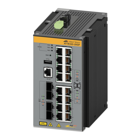
Chapter 1: Overview IE340-12GT The front panel of the IE340-12GT switch is shown in Figure 2. Status LEDs Reset button USB port Console management port Slots for 10/100/1000Base-T 100/1000Base-X twisted pair ports SFP transceivers Figure 2. Front Panel of the IE340-12GT Switch IE340-20GP The front panel of the IE340-20GP Switch is shown in Figure 3. -
Page 22: Ie340L-18Gp
IE340 Series Installation Guide IE340L-18GP The front panel of the IE340L-18GP switch is shown in Figure 4. Status LEDs Reset button Console management port 10/100/1000Base-T twisted pair ports Slots for 1000Base-X SFP transceivers Figure 4. Front Panel of the IE340L-18GP Switch... -
Page 23: Back Panel
Chapter 1: Overview Figure 6 identifies the components on the top panel of the IE340-12GT switch. Grounding screw Alarm In connector Alarm Out connector PWR 1 DC power connector PWR 2 DC power connector Figure 6. Top Panel of the IE340-12GT Switch Back Panel Figure 7 identifies the components on the back panel. -
Page 24: Features
IE340 Series Installation Guide Features Here are the basic features of the switches. Twisted Pair Here are the basic features of the twisted pair ports: Ports Sixteen ports on the IE340-20GP and IE340L-18GP switches Eight ports on the IE340-12GP and IE340-12GT switches ... -
Page 25: Sfp Slots
Chapter 1: Overview SFP Slots The number of SFP slots and types of supported transceivers are given here: Four SFP slots on the IE340-12GP, IE340-12GT and IE340-20GP switches Two SFP slots on the IE340L-18GP switch 100Base-FX transceivers (All models except the IE340L-18GP ... -
Page 26: Leds
IE340 Series Installation Guide LEDs The switches have the following LEDs: System fault Status of the power supplies Link/activity of the SFP and twisted pair ports Duplex mode of the twisted pair ports on the IE340-12GT switch ... -
Page 27: Twisted Pair Ports
Chapter 1: Overview Twisted Pair Ports This section describes the twisted pair ports. Connector Type The twisted-pair ports have 8-pin RJ-45 connectors. The ports use four pins at 10 or 100 Mbps and all eight pins at 1000 Mbps. The pin assignments are listed in Table 23 on page 132 and Table 24 on page 133. -
Page 28: Cable Requirements
IE340 Series Installation Guide Cable Minimum cable requirements for the twisted pair ports are listed here: Requirements 10Mbps operations: Standard TIA/EIA 568-compliant Category 3, 100 ohm shielded or unshielded cabling, complying with IEEE 802.3i 10Base-T specifications. 100Mbps operations: Standard TIA/EIA 568-compliant Category 5, ... -
Page 29: Power Over Ethernet
Chapter 1: Overview Power over Ethernet The section explains the Power over Ethernet (PoE) Power Sourcing Equipment (PSE) feature for the following IE340 switches: IE340-12GP IE340-20GP IE340L-18GP Note The IE340-12GT switch does not support PoE PSE. The PoE PSE feature allows the switches to supply electrical power to network devices over the same twisted pair cables that carry network traffic. -
Page 30: Powered Device Classes For Poe And Poe
IE340 Series Installation Guide PoE+ devices: Standard TIA/EIA 568-compliant Category 5e, 4- pair shielded or unshielded cabling. Category 6 is recommended. Note Category 3 and 5 cables may be used for EN55024 immunity levels; however, they are not recommended for IEC61000-6-2 and EN50121-4 immunity levels. -
Page 31: Poe Power Budget
Chapter 1: Overview strands. In Alternative A, power is delivered on strands 1, 2, 3, and 6, which are the same strands that carry the 10/100Base-TX network traffic. In Alternative B, power is delivered on strands 4, 5, 7, and 8. These are the unused strands. - Page 32 IE340 Series Installation Guide There are three priority levels: Critical High Ports set to the Critical level, the highest priority level, are guaranteed power before any of the ports assigned to the other two priority levels. Ports assigned to the other priority levels receive power only if all the Critical ports are receiving power.
-
Page 33: Sfp Slots
Chapter 1: Overview SFP Slots The following IE340 switches have four slots for 100/1000Base-X fiber optic, MSA-compliant SFP transceivers: IE340-12GP IE340-12GT IE340-20GP The IE340L-18GP switch has two SFP slots for Ethernet 1000Base-X fiber optic, MSA-compliant SFP transceivers. You can use transceivers to connect switches to other network devices over large distances, build a high-speed backbone network between network devices, or connect high-speed devices, such as servers, to your... -
Page 34: Console Port
IE340 Series Installation Guide Console Port The Console port is a serial RS-232 port. You use the port to access the AlliedWare Plus management software to configure the features. Management sessions conducted through the Console port are called local management sessions because you have to be at the location of the switch. -
Page 35: Usb Port
Chapter 1: Overview USB Port The USB port can be used with a flash drive for the following management functions: Use Allied Telesis Management Framework to provide a centralized network backup location. Store backup copies of configuration files. ... -
Page 36: Reset Button
IE340 Series Installation Guide Reset Button The Reset button resets the switch. You might reset the switch if it is experiencing a problem. The reset button is recessed in the chassis. To press it, use a straightened paper-clip or similar object. -
Page 37: Pwr 1 And Pwr 2 Dc Power Connectors
The switches support the following types of power sources: AC/DC rectifiers Un-interruptible power supplies For power supply requirements, see “Power Supplies” on page 49. Note The AT-iMG008 Power Supply and Backup Unit from Allied Telesis is not compatible with IE340 switches. -
Page 38: Alarm In Connector
IE340 Series Installation Guide Alarm In Connector The switch has a 2-pin Alarm In (ALM IN) connector for an external sensor on the top panel. The switch can use an external sensor to monitor the wiring room or cabinet for unauthorized access or for changes in the room’s environment, such as the temperature or humidity. -
Page 39: Figure 8: Example 1 Of The Alarm In (Alm In) Connector
Chapter 1: Overview The example in Figure 8 shows the Alarm In connector attached to a door sensor. The sensor is installed such that it is closed (on) when the door is closed and open (off) when the door is open. Door Sensor: Alarm In connector: Door closed - circuit closed... -
Page 40: Figure 9: Example 2 Of The Alarm In (Alm In) Connector
The command configures the switch to signal the alarm when the sensor changes to closed above 30° C. When the temperature falls below 30° C, and the temperature sensor changes from closed to open, the switch automatically cancels the alarm. Note External sensors are not available from Allied Telesis. -
Page 41: Alarm Out Connector
Chapter 1: Overview Alarm Out Connector The switch has a 2-pin Alarm Out (ALM OUT) connector on the top panel for an external alert device. The switch can use the device to alert you to alarm conditions, such as power supply failures or ports without links. Here are two examples of alert devices for the Alarm Out connector: LEDs ... -
Page 42: Din Rail Bracket
LED. When the switch detects that all its ports have links again, it closes the circuit, which turns off the LED. Note Alarm devices are not available from Allied Telesis. Blue LED Circuit closed - LED off Circuit open - LED on Figure 10. -
Page 43: Leds
1 does not have a link to a network device: alarm facility link-down port1.0.1 led For more information, refer to the Software Reference for IE340 Series Switches or Command Reference for IE340 Series Switches. Six flashes The switch is overheating and might in two shutdown. - Page 44 IE340 Series Installation Guide Table 4. Status LEDs (Continued) State Description PWR1 The switch is not receiving power on the PWR 1 connector or the input power from the DC power supply is outside the normal operating range of the unit.
-
Page 45: Twisted Pair Port Leds On Poe Pse Switches
Chapter 1: Overview Twisted Pair Port The twisted pair ports on the IE340 PoE PSE switches have two LEDs each. The LEDs are identified in Figure 11. LEDs on PoE PSE Switches PoE LED PoE LED L/A LED L/A LED PoE LED PoE LED L/A LED... -
Page 46: Twisted Pair Port Leds On The Ie340-12Gt Switch
IE340 Series Installation Guide Table 5. Twisted Pair Port LEDs on the PoE PSE Switches (Continued) State Description Solid Green The port has established a 1000 Mbps link to a network device. Flashing The port is transmitting or receiving data at 1000 Green Mbps. -
Page 47: Sfp Slot Leds
Chapter 1: Overview Table 6. Twisted Pair Port LEDs on the IE340-12GT Switch State Description Solid Green The port is operating in full duplex mode. Duplex Solid Amber The port is operating in half duplex mode. Mode The port has not established a link with a network device. -
Page 48: Table 8: Sfp Slot Led For Ie340L-18Gp Model
IE340 Series Installation Guide Table 8. SFP Slot LED for IE340L-18GP Model State Description Solid Green The port has established a 1Gbps link to a network device. Flashing Green The port is transmitting or receiving network packet traffic at 1Gbps. -
Page 49: Power Supplies
Power Supplies IE340 switches can be powered with the IE048-480 power supply from Allied Telesis. They can also be powered with power supplies from third- party manufacturers that meet the requirements in Table 9 on page 51 and “Power Specifications” on page 130. They should also support the environment of the location site. -
Page 50: Power Requirements
IE340 Series Installation Guide Caution The output power of the IE048-480 power supply is affected by the input voltage and ambient temperature. Refer to the data sheet for the derating curve. The IE048-480 power supply is sold separately. Power The IE340 switches have the following power supply requirements:... -
Page 51: Table 9: Input Voltage Requirements
Chapter 1: Overview Table 9. Input Voltage Requirements Over- Input Voltage Mode Input Voltage Range voltage Recommended Alarm Non-PoE IE340-12GP 18.0 to 57.0 VDC 24 VDC, 48 VDC IE340-12GT IE340-20GP ≥ 57 VDC IE340L-18GP 46.0 to 57.0 VDC 48 VDC 46.0 to 57.0 VDC 54 VDC 52.5 to 57.0 VDC... - Page 52 IE340 Series Installation Guide...
-
Page 53: Chapter 2 : Beginning The Installation
Chapter 2 Beginning the Installation The chapter contains the following sections: “Reviewing Safety Precautions” on page 54 “Safety Precautions When Working with Electricity” on page 58 “Reviewing Site Requirements” on page 59 “Unpacking the Product Package” on page 63 ... -
Page 54: Reviewing Safety Precautions
IE340 Series Installation Guide Reviewing Safety Precautions Please review the following safety precautions before beginning the installation procedures. Note Safety statements that have the symbol are translated into multiple languages in the Translated Safety Statements document at www.alliedtelesis.com/support. Warning Class 1 Laser product. - Page 55 Chapter 2: Beginning the Installation Note An appropriate disconnect device must be provided as part of the building or enclosure installation. Warning Use a UL-listed DC power supply having 48VDC/10A output and being suitable for the maximum operating altitude of 3,000 m and the maximum ambient temperature of the switch’s location.
- Page 56 IE340 Series Installation Guide Warning This unit might have more than one power cord. To reduce the risk of electric shock, disconnect all power cords before servicing the unit. E30 Caution The unit does not contain serviceable components. Please return damaged units for servicing.
- Page 57 Chapter 2: Beginning the Installation Note The equipment meets EN61000-4-5 Class 3 on the DC inputs and Ethernet ports. Note Allied Telesis does not warrant against lightning or power surges damaging the device. Such damage will be the responsibility of the equipment owner.
-
Page 58: Safety Precautions When Working With Electricity
IE340 Series Installation Guide Safety Precautions When Working with Electricity Please review the following additional safety guidelines before beginning the installation procedure. Disconnect all power by turning off the circuit breakers before installing or removing the device or when working with the power supplies. -
Page 59: Reviewing Site Requirements
Chapter 2: Beginning the Installation Reviewing Site Requirements Please observe the following requirements and guidelines when choosing a site for the switch: Warning You must install the switch in a UL Listed 3X or 4X enclosure when installing it in an outdoor environment. The switch does not require an enclosure when installed in most ... - Page 60 If the product overheats in an enclosure that was built without taking into account these factors, the warranty of the product might be voided. Consult Allied Telesis when assistance is needed. The enclosure BTU/hour rating must be higher than the total BTU/ ...
-
Page 61: Table 10: Ground Resistivity Recommendations
The twisted pair cabling should not be exposed to sources of electrical noise, such as radio transmitters, broadband amplifiers, power lines, electric motors, and fluorescent lights. Allied Telesis recommends using CAT6 STP or UTP for LAN ports. These cables provide higher protection from radio frequency interference. -
Page 62: Figure 13: Space Issue Between Sfp Module And Copper Port
IE340 Series Installation Guide Figure 13. Space Issue Between SFP Module and Copper Port... -
Page 63: Unpacking The Product Package
Chapter 2: Beginning the Installation Unpacking the Product Package To unpack the product package, perform the following procedure: 1. Remove all the components from the shipping box. Refer to Figure 14. Note Store the packaging material in a safe location. You must use the original shipping material if you need to return the unit to Allied Telesis. -
Page 64: Figure 15: Removing The Switch From The Anti-Static Bag
IE340 Series Installation Guide 2. Remove the switch from the anti-static bag and place it on a level, secure surface. Refer to Figure 15. Figure 15. Removing the Switch from the Anti-static Bag 3. Verify that the shipping container includes the items shown in Table 11 on page 65. -
Page 65: Figure 16: Pre-Installed Components
Chapter 2: Beginning the Installation Figure 16. Pre-installed Components Table 11. Shipping Package Contents IE340-12GP IE340- IE340L- IE340-12GT 20GP 18GP Shipping Component Number of the Components Dust cover on the USB port (Pre-installed) Dust covers on the copper and Console ports (Pre-installed) - Page 66 IE340 Series Installation Guide Table 11. Shipping Package Contents (Continued) IE340-12GP IE340- IE340L- IE340-12GT 20GP 18GP Shipping Component Number of the Components Dust covers on the SFP slots (Pre-installed) M4x8 Phillips- head grounding screw (Pre-installed) 2-pin connectors on the ALM IN...
- Page 67 Chapter 2: Beginning the Installation Table 11. Shipping Package Contents (Continued) IE340-12GP IE340- IE340L- IE340-12GT 20GP 18GP Shipping Component Number of the Components Wall bracket M4x8 Phillips- head screws 2m (6.6ft) local management cable with RJ-45 (8P8C) and DB0 (D-sub 9-pin) connectors...
- Page 68 IE340 Series Installation Guide...
-
Page 69: Chapter 3 : Installing The Switch
Chapter 3 Installing the Switch The procedures in this chapter are listed here: “Installing the Switch on a DIN Rail” on page 70 “Installing the Switch on an Indoor Wooden Wall” on page 73 “Installing the Switch on an Indoor Concrete Wall” on page 79 ... -
Page 70: Installing The Switch On A Din Rail
IE340 Series Installation Guide Installing the Switch on a DIN Rail The switch comes with a DIN rail bracket pre-installed on the back panel. The bracket is compatible with DIN 35 x 7.5mm rails. Figure 17 shows the switch installed on a DIN rail. -
Page 71: Figure 19: Installing The Switch On A Din Rail - 1
Chapter 3: Installing the Switch To install the switch on a DIN rail, perform the following procedure: 1. Hold the switch with both hands facing toward the DIN rail on the wall. 2. Tilt the bottom of the switch towards the wall and hook the bottom of the switch bracket on the bottom edge of DIN rail. -
Page 72: Figure 21: Verifying The Din Rail Installation
Allied Telesis recommends installing DIN rail end clamps to the sides of the switch to prevent damage or network traffic loss from vibration or shock. End clamps are not available from Allied Telesis. 5. Go to Chapter 4, “Cabling the Ports” on page 87. -
Page 73: Installing The Switch On An Indoor Wooden Wall
E105 Allied Telesis recommends using a plywood base when installing the switch on a wall with wooden studs. The base allows you to mount the device on two studs in the wall. (A plywood base is not required for a... -
Page 74: Figure 22: Switch On The Wall With A Plywood Base
IE340 Series Installation Guide Wall Studs Wall Plywood Base Figure 22. Switch on the Wall with a Plywood Base The recommended minimum dimensions of the plywood base are listed here: Width: 58.4 centimeters (23 inches) Height: 28.0 centimeters (11 inches) ... -
Page 75: Tools And Material
Chapter 3: Installing the Switch Wall Studs Wall Plywood Base Step 2: Install the Step 1: Install the switch on the plywood base on plywood base. the wall. Figure 23. Steps to Installing the Switch with a Plywood Base Tools and Here are the tools and material required for installing the switch on a wooden wall: Material... -
Page 76: Installing The Switch On The Plywood Base
IE340 Series Installation Guide Installing the This procedure assumes that the plywood base for the switch is installed on the wall. Please review “Reviewing Safety Precautions” on page 54 Switch on the and “Reviewing Site Requirements” on page 59 before performing this Plywood Base procedure. -
Page 77: Figure 25: Installing The Wall Brackets On The Switch
Chapter 3: Installing the Switch 3. Install the two wall brackets to the back panel of the switch, with the four screws included with the unit. Refer to Figure 25. Figure 25. Installing the Wall Brackets on the Switch 4. Have another person hold the switch on the plywood base on the wall while you secure it with four screws (not provided). -
Page 78: Figure 26: Attaching The Switch To The Plywood Base
IE340 Series Installation Guide Figure 26. Attaching the Switch to the Plywood Base 5. Go to Chapter 4, “Cabling the Ports” on page 87. -
Page 79: Installing The Switch On An Indoor Concrete Wall
Chapter 3: Installing the Switch Installing the Switch on an Indoor Concrete Wall This section contains the procedure for installing the switch on a concrete wall in a protected, indoor environment. Note The switch does not require an enclosure when installed in most indoor environments. - Page 80 IE340 Series Installation Guide Here are the tools and material required for installing the switch on a concrete wall: Two wall brackets (included with the switch) Four bracket screws (included with the switch) Four wall screws (not provided) ...
-
Page 81: Figure 27: Marking The Locations Of The Bracket Holes On A Concrete Wall
Prior to drilling, set the drill to hammer and rotation mode. The modes break up the concrete and clean out the hole. Allied Telesis recommends cleaning out the holes with a brush or compressed air. 7. Insert four anchors (not provided) into the holes. -
Page 82: Figure 28: Installing The Switch On A Concrete Wall
IE340 Series Installation Guide Figure 28. Installing the Switch on a Concrete Wall 9. Go to Chapter 4, “Cabling the Ports” on page 87. -
Page 83: Installing The Switch In An Outdoor Environment
Consult Allied Telesis when assistance is needed. Immunity and The IE340 switches are suitable for industrial applications, which require... -
Page 84: Lightning Protection Requirements
The IE340 switches have a surge immunity of up to 2 kV. This is sufficient when interconnection cables are partly outdoor cables and close to the grounding network. If this condition is not satisfied, Allied Telesis strongly recommends installing primary surge protections, which are usually provided by the use of solid state or gas tube arrestors located at the point where the cable enters the building or the outdoor cabinet. - Page 85 Chapter 3: Installing the Switch Note The users of the plant or those responsible for the installation should apply the necessary measures (e.g. shielding, bonding, and grounding protection) to ensure that the interference voltages caused by lighting strokes do not exceed the available immunity level.
- Page 86 IE340 Series Installation Guide...
-
Page 87: Chapter 4 : Cabling The Ports
Chapter 4 Cabling the Ports This chapter contains the following procedures: “Cabling the Twisted Pair Ports” on page 88 “Installing SFP Transceivers” on page 90 ... -
Page 88: Cabling The Twisted Pair Ports
IE340 Series Installation Guide Cabling the Twisted Pair Ports Here are the guidelines to cabling the twisted pair ports: The ports have 8-pin RJ45 connectors. The connectors on the cables should fit snugly into the ports, and the tabs should lock the connectors into place. - Page 89 Properly rated primary protection devices must be installed on the cables before connecting them to the switch. When you use an SFP module, Allied Telesis recommends leaving the adjacent copper port unused. When an SFP slot and its right- side copper port are used, the space between the SFP module and port cable is so limited that disconnecting the cable is difficult.
-
Page 90: Installing Sfp Transceivers
This is because of the design of the SFP cages. When you use an SFP module, Allied Telesis recommends leaving the adjacent copper port unused. When an SFP slot and its right- side copper port are used, the space between the SFP module and port cable is so limited that disconnecting the cable is difficult. -
Page 91: Figure 29: Removing The Dust Plug From An Sfp Slot
Chapter 4: Cabling the Ports 1. Remove the dust plug from a transceiver slot. Figure 29 on page 91 shows the dust plug removed from slot 1. Figure 29. Removing the Dust Plug from an SFP Slot 2. Remove the transceiver from its shipping container and store the packaging material in a safe location. -
Page 92: Figure 31: Removing The Dust Cover From An Sfp Transceiver
IE340 Series Installation Guide Note If you are ready to attach the fiber optic cable to the transceiver, continue with the next step. Otherwise, repeat steps 1 to 3 to install the remaining transceivers in the switch. 4. Remove the dust cover from the transceiver. Refer to Figure 31. -
Page 93: Figure 33: Connecting A Fiber Optic Cable To An Sfp Transceiver
Chapter 4: Cabling the Ports Figure 33. Connecting a Fiber Optic Cable to an SFP Transceiver 7. Repeat this procedure to install and cable the remaining transceivers. 8. Go to Chapter 5, “Powering On the Switch” on page 95. - Page 94 IE340 Series Installation Guide...
-
Page 95: Chapter 5 : Powering On The Switch
Chapter 5 Powering On the Switch This chapter contains the following procedures: “Connecting the Grounding Wire” on page 96 “Wiring the ALM IN and ALM OUT Connectors” on page 99 “Preparing the DC Power Cables” on page 104 ... -
Page 96: Connecting The Grounding Wire
IE340 Series Installation Guide Connecting the Grounding Wire Here are the guidelines for the grounding wire: The wire should be minimum #16 AWG solid wire. The wire length should be as short as possible. Continuity from the grounding screw to the earth ground must be ... -
Page 97: Figure 35: Loosening The Grounding Screw
Chapter 5: Powering On the Switch Figure 35. Loosening the Grounding Screw 3. Wrap the grounding wire clockwise around the base of the grounding screw. Refer to Figure 36. Figure 36. Wrapping the Grounding Wire Around the Grounding Screw 4. Tighten the screw to secure the grounding wire to the switch. Refer to Figure 37 on page 98. -
Page 98: Figure 37: Securing The Grounding Wire To The Switch
IE340 Series Installation Guide Figure 37. Securing the Grounding Wire to the Switch 5. Connect the other end of the ground wire to a ground point at the installation site. 6. Do one of the following: To wire the alarm connectors, go to “Wiring the ALM IN and ALM ... -
Page 99: Wiring The Alm In And Alm Out Connectors
Chapter 5: Powering On the Switch Wiring the ALM IN and ALM OUT Connectors For background information on the alarm connectors, refer to “Alarm In Connector” on page 38 and “Alarm Out Connector” on page 41. Here are general guidelines to the alarm connectors: Use 24 to 18 AWG stranded wire properly rated for the installation ... -
Page 100: Figure 38: Polarity Legend For The Alarm Connectors
IE340 Series Installation Guide Before wiring an alarm connector, familiarize yourself with the negative and positive polarities of its two pins by examining the legends on the top panel. Refer to Figure 38. Figure 38. Polarity Legend for the Alarm Connectors The following procedure shows the ALM OUT connector. -
Page 101: Figure 40: Wrapping The Wire Strands
Chapter 5: Powering On the Switch Figure 40. Wrapping the Wire Strands Note Allied Telesis recommends tinning the wires with solder for added protection against loose strands. This guide does not provide instructions on how to tin wires. 3. Remove the alarm connector from the top panel. Figure 41 shows the removal of the ALM OUT connector. -
Page 102: Figure 43: Inserting The Wires Into The Dc Cable Connector
IE340 Series Installation Guide 5. Insert the wires into the connector and tighten the retaining screws to secure the wires. Refer to Figure 43. Allied Telesis recommends tightening the screws to 2 to 3 in.-lbs. Positive (+) Negative (-) Figure 43. Inserting the Wires into the DC Cable Connector 6. -
Page 103: Figure 44: Inserting The Dc Connector Into The Alarm Connector
Chapter 5: Powering On the Switch Figure 44. Inserting the DC Connector into the Alarm Connector 8. Connect the other end of the wires to an external sensor for the Alarm In connector or an alert device for the Alarm Out connector. 9. -
Page 104: Preparing The Dc Power Cables
IE340 Series Installation Guide Preparing the DC Power Cables You can power the switch with either one or two DC power supplies. For power supply specifications, refer to “Power Supplies” on page 49. Power supplies are connected to the 4-wire, DC power connector on the top panel of the switch. -
Page 105: Figure 46: Stripping A Power Cable Wire
This step is to prevent loose strands from touching other wires and causing an electrical short. Note Allied Telesis recommends tinning the wires with solder as added protection against loose strands. This guide does not provide instructions on how to tin wires. -
Page 106: Figure 48: Loosening The Wire Retaining Screws On The Pwr 1 - Pwr 2 Cable Connector
Cable Connector 5. Insert the wires into the connector and tighten the retaining screws to secure the wires. Refer to Figure 49. Allied Telesis recommends tightening the screws to 2 to 3 in.-lbs. PWR 1 PWR 2 Figure 49. Inserting the Wires into the PWR 1 - PWR 2 Cable Connector 6. -
Page 107: Figure 50: Verifying The Wire Installation
Chapter 5: Powering On the Switch Incorrect - Loose wire Correct Incorrect - Exposed wire. strands Figure 50. Verifying the Wire Installation Warning Check to see if there are any exposed copper strands coming from the installed wires. When this installation is done correctly there should be no exposed copper wire strands extending from the terminal block. -
Page 108: Powering On The Switch
IE340 Series Installation Guide Powering On the Switch This section contains the procedure for powering on the switch. Note The switch can update its release or configuration file from a USB flash drive during the initial power up of the unit. This is called the Autoboot feature. -
Page 109: Verifying Switch Operations
Chapter 5: Powering On the Switch Note The switch does not have an On/Off switch. 5. Wait several minutes for the switch to initialize its operating system. To monitor the console messages as the device initializes the management software, go to “Monitoring the Initialization Process” on page 110. -
Page 110: Monitoring The Initialization Process
IE340 Series Installation Guide Monitoring the Initialization Process It takes several minutes for the switch to initialize its operating system and load the default configuration. You can monitor the bootup sequence by connecting a terminal or computer with a terminal emulator program to the Console port on the front panel. -
Page 111: Figure 53: Initialization Messages (Continued)
Chapter 5: Powering On the Switch Starting base/crond... [ OK ] starting base/appmond... [ OK ] Starting base/clockcheck... [ OK ] Starting network/execd... [ OK ] Starting base/inet... [ OK ] Received event apteryx.done Starting hardware/early_host_info... [ OK ] Starting base/alfred... [ OK ] Starting network/kermond... -
Page 112: Figure 54: Initialization Messages (Continued)
IE340 Series Installation Guide Received event network.activated Loading configuration file flash:/test1.cfg, please wait. done! Received event network.activated awplus login: Figure 54. Initialization Messages (Continued) -
Page 113: Starting A Local Management Session
Chapter 5: Powering On the Switch Starting a Local Management Session This section contains the procedure for starting a local management session on the switch. Please review the following information before performing the procedure: The initial management session with the switch must be a local ... - Page 114 IE340 Series Installation Guide Note The baud rate must be set to the default 9600 bps to configure the boot loader. 4. Press Enter. You are prompted for the name and password of the manager account. 5. Enter the user name and password. The default values are “manager”...
-
Page 115: Verifying Poe
Chapter 5: Powering On the Switch Verifying PoE This section contains procedures for verifying and, if necessary, configuring the PoE budget on IE340 PoE PSE switches. The procedures are listed here: “Verifying the PoE Budget,” next “Configuring the Provisioned PoE Budget” on page 116 ... -
Page 116: Configuring The Provisioned Poe Budget
IE340 Series Installation Guide The default PoE values for ports sourcing PoE are listed here: PoE is enabled. The wiring configuration is Alternative A. (This parameter is not adjustable.) No further configuration steps are required for ports connected to the... - Page 117 Chapter 5: Powering On the Switch 3. Do one of the following: If the values in the Nominal Power and Power Allocated fields are the same, no further installation steps are required. Refer to the Software Reference for the IE340 Switches for management instructions.
- Page 118 IE340 Series Installation Guide...
-
Page 119: Troubleshooting
“PWR 1 and PWR 2 LEDs” on page 120 “Twisted Pair Ports” on page 121 “SFP Slots” on page 123 “Power Over Ethernet” on page 124 Note For further assistance, contact Allied Telesis Technical Support at www.alliedtelesis.com/support. -
Page 120: Pwr 1 And Pwr 2 Leds
IE340 Series Installation Guide PWR 1 and PWR 2 LEDs Problem: A DC power supply is connected to the switch, but the corresponding PWR 1 or PWR 2 LED on the front panel is off. Solutions: The unit is not receiving power from the power supply or the power is outside the operating range of the switch. -
Page 121: Twisted Pair Ports
Chapter 6: Troubleshooting Twisted Pair Ports Problem: The switch is powered on and forwarding traffic, but all the port LEDs are off. Solutions: The port LEDs may have been turned off with the ECOFRIENDLY LED command in the AlliedWare Plus operating system. To turn on the LEDs, establish a management session with the unit and issue the NO ECOFRIENDLY LED command in the Global Configuration mode. - Page 122 IE340 Series Installation Guide Problem: Network performance between a twisted pair port on the switch and a network device is slow. Solution: There might be a duplex mode mismatch between the port and the network device. This can occur when a twisted pair port using Auto- Negotiation is connected to a remote device that has a fixed speed of 10 or 100 Mbps and a fixed duplex mode of full duplex.
-
Page 123: Sfp Slots
Chapter 6: Troubleshooting SFP Slots Problem: The LINK/ACT LED for an SFP transceiver is off. Solutions: The fiber optic port on the transceiver cannot establish a link to a network device. Try the following: Verify that the remote network device connected to the fiber optic ... -
Page 124: Power Over Ethernet
IE340 Series Installation Guide Power Over Ethernet Problem: The switch sourcing PoE is not providing power to the connected PoE powered devices Solutions: Try the following: Check that the device’s power requirements do not exceed those listed in Table 1 on page 29. The power requirements should be included in the device’s documentation or data sheet. -
Page 125: Appendix A: Technical Specifications
Appendix A Technical Specifications This appendix contains the following sections: “Physical Specifications” on page 126 “Environmental Specifications” on page 128 “Power Specifications” on page 130 “RJ-45 Twisted Pair Port Pinouts” on page 132 “RJ-45 Style Serial Console Port Pinouts” on page 134 ... -
Page 126: Physical Specifications
IE340 Series Installation Guide Physical Specifications Dimensions Table 12. Product Dimensions (W x H x D) IE340 switches 9.1 x 15.3 x 13.9 cm (3.58 x 6.02 x 5.47 in.) Weights Table 13. Product Weights IE340 switch with DIN rail bracket 2.34 kg (5.16 lbs) - Page 127 If the product overheats in an enclosure that was built without taking into account these factors, the warranty of the product might be voided. Consult Allied Telesis when assistance is needed.
-
Page 128: Environmental Specifications
IE340 Series Installation Guide Environmental Specifications Table 16. Operating Temperature Ratings Operating Temperature Ranges Enclosure Type Model Name Rating Sealed Ventilated Cooling Fan Enclosure: Airflow: Airflow: 0 lfm 240 lfm 2150 lfm IE340-12GP -40°C to 65°C -40°C to 70°C -40°C to 75°C (-40°... - Page 129 Appendix A: Technical Specifications Note The switch does not require an enclosure when installed in most indoor environments. However, the switch must be installed in a UL Listed or Nationally Recognized Test Lab enclosure when used in an indoor Measurement, Control, or Laboratory environment, as specified in UL/EN/IEC 61010-1 and 61010-2-201.
-
Page 130: Power Specifications
IE340 Series Installation Guide Power Specifications Table 19. Input Voltage Specifications Switch PoE+ Non-PoE 18-57VDC IE340-12GP 46-57VDC 52.5-57VDC 18-57VDC IE340-20GP 46-57VDC IE340L-18GP 18-57VDC IE340-12GT Table 20. Maximum Power Consumptions IE340-12GP 271 watts (including PDs’ consumption IE340-20GP 31 watts (excluding PDs’ consumption) -
Page 131: Table 22: Alm In And Alm Out Power Ratings
Appendix A: Technical Specifications Table 22. ALM IN and ALM OUT Power Ratings 30VDC maximum 0.5A maximum ALARM OUT 3.3VDC minimum 320uA ALARM IN Note For ALARM IN and ALARM OUT wiring specifications, see “Wiring the ALM IN and ALM OUT Connectors” on page 99. -
Page 132: Rj-45 Twisted Pair Port Pinouts
IE340 Series Installation Guide RJ-45 Twisted Pair Port Pinouts Figure 55 identifies pin 1 on an RJ-45 twisted pair port. Figure 55. RJ-45 Port Pin Layout (Front View) Table 23 lists the pin signals for a port when it is operating at 10 or 100 Mbps. -
Page 133: Table 24: Pin Signals For 1000 Mbps
Appendix A: Technical Specifications Table 24 lists the pin signals for a port when it operating at 1000 Mbps. Table 24. Pin Signals for 1000 Mbps Pinout Pair Pair 1 + Pair 1 - Pair 2 + Pair 3 + Pair 3 - Pair 2 - Pair 4 +... -
Page 134: Figure 56: Console Port Pin Layout (Front View)
IE340 Series Installation Guide RJ-45 Style Serial Console Port Pinouts Figure 56 identifies pin 1 on the RJ-45 connector on the Console port. Pin 1 Figure 56. Console Port Pin Layout (Front View) Table 25 lists the pin signals for the RJ-45 style serial Console port. -
Page 135: Table 26: Pwr 1 And Pwr 2 Dc Connector Pin Signals On The Ie340-12Gp, Ie340-12Gt, And Ie340-20Gp Switches
Appendix A: Technical Specifications PWR 1 and PWR 2 DC Power Connectors Table 26. PWR 1 and PWR 2 DC Connector Pin Signals on the IE340-12GP, IE340-12GT, and IE340-20GP Switches Signal 24/48/54 VDC VDC Return Table 27. PWR 1 and PWR 2 DC Connector Pin Signals on the IE340L-18GP Switch Signal 48/54 VDC... -
Page 136: Figure 57: Ie340 Switch Dimensions
IE340 Series Installation Guide Device Dimensions 138.254 [5.443] 56.7 [2.232] 162.064 [6.380] 153 [6.024] 96.3 [3.791] 91 [3.583] 148.45 [5.844] [1.732] [1.378] 18.2 [.276] [.717] 17.6125 [7.559] [.693] [5.472] 174.225 [6.859] [2.598] [1.378] Figure 57. IE340 Switch Dimensions...
Need help?
Do you have a question about the IE340 Series and is the answer not in the manual?
Questions and answers