Advertisement
Quick Links
Advertisement

Related Manuals for Clayton Power LPS


Summary of Contents for Clayton Power LPS
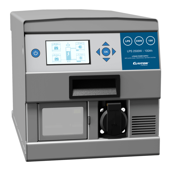
- Page 1 Lithium Power Supply LPS - Van Installation Guide V1.2...
- Page 2 Van Installation Guide LPS - Van Installation Guide Common setup with main functions: 12 V Output 230 V Output Charging from the van Charging from mains LPS Remote 1a Unpacking 1b Mounting Charging from the van 2a Starter battery 2b D+ Ignition signal...
- Page 3 Starter Battery Ignition Signal Mains connection LPS Remote...
- Page 4 Van Installation Guide LPS - Lithium Power Supply Unpacking LPS - Lithium Power Supply Neutrik 230 V Connector 1x Blue: 230 V / 50 Hz IN 1x Grey: 230 V / 50 Hz OUT 1a Unpacking Anderson SB50 DC Connector...
- Page 6 Van Installation Guide LPS - Lithium Power Supply Mounting LPS Mounting Console (recommended) Mount the LPS in the van by using an LPS Mounting Console and 4 screws D4,20. Part No.: ACWO00107GF Dimensions: 420 x 300 x 55 mm Not included the LPS as standard.
- Page 7 ATTENTION: Mount the LPS topside up, never upside down or on the side. ATTENTION: The LPS has forced air cooling. Make sure air can flow freely around the unit. The LPS has four M5 mounting holes in the bottom.
-
Page 8: Starter Battery
Charging from the van Starter Battery LPS (12 VDC IN) Starter Battery Connect the LPS to plus and minus pole on the starter battery. Plus to Plus - including 100A DC fuse Minus to Minus (direct connection is recommended) Use 16 mm2 cable. Maximum length: 5m... - Page 9 12 VDC IN Note: Assembling the power cable correctly is important as the power load may be high.
- Page 10 Van Installation Guide Charging from the van D+ Ignition signal LPS (COMMUNICATION - PIN 9) D+ Ignition signal For automatic charging when the van turns on. Connect a 0,75 mm wire to pin 9 in the DB9 connector to the van’s fuse box with D+ ignition signal.
- Page 11 COMMUNICATION...
-
Page 12: Mains Connection
Van Installation Guide Charging from mains Mains connection LPS (230 V IN) Mains connector/plug Connect the Blue Neutrik with a power cord to a 230 V plug/connector. Example: 1a Unpacking 1b Mounting MiniPlug inlet cable for mounting in the bumper. - Page 13 230 V / 50 Hz IN 20 mm [0.787”] .32"] PE 23 mm [0.9”] Example: Wire Ferrules to secure connection to terminal blocks.
- Page 14 Van Installation Guide Outputs 12V Output LPS (12VDC OUT) 12V Appliances Connect all fixed 12 V appliances in the van via a DC fuse box. Use 16 mm2 cable. Maximum length 5 m. 1a Unpacking 1b Mounting Charging from the van...
- Page 15 12 VDC OUT Note: Assembling the power cable correctly is important as the power load may be high.
- Page 16 1b Mounting Charging from the van Fuses Both 230 V outputs on the LPS (Schuko on the front, Neutrik in the 2a Starter battery back) are protected with 8 A or 10 A relays (depending on model) and 2b Ignition signal an RCD, which allow you to make fixed 230 V installations in the van.
- Page 17 230 V / 50 Hz OUT 20 mm [0.787”] .32"] PE 23 mm [0.9”] Example: Wire Ferrules to secure connection to terminal blocks.
- Page 18 The brown wire is not in use. 1a Unpacking LPS Remote 1b Mounting The LPS Remote is fitted with a 6m cable Charging from the van and a bracket. 2a Starter battery The LPS Remote is not included with the 2b Ignition signal LPS as standard.
- Page 19 COMMUNICATION LPS Remote Mounting Bracket...
- Page 20 Van Installation Guide Test Push the 12 V LPS Remote button Check that the LPS starts up and 12 V appliances turn on Push the 230 V LPS Remote button 1a Unpacking Check that the LPS turns on 230 V and test 230 V...
Need help?
Do you have a question about the LPS and is the answer not in the manual?
Questions and answers