
Related Manuals for Reclaim REHP-CO2-160GL

Summary of Contents for Reclaim REHP-CO2-160GL
- Page 1 OWNER/ INSTALLATION MANUAL AIR-SOURCE CO2 HEAT PUMP HOT WATER SYSTEM INSTALLATION OPERATION/MAINTENANCE WARRANTY CALL: 1300 383 815 EMAIL: HELLO@RECLAIMENERGY.COM.AU VISIT: RECLAIMENERGY.COM.AU...
- Page 2 COVERING MODEL NUMBERS (FOR STC CLAIMS): REHP-CO2-160GL REHP-CO2-160SST REHP-CO2-250GL REHP-CO2-250SST REHP-CO2-315GL REHP-CO2-315SSQ REHP-CO2-315SST REHP-CO2-400GL REHP-CO2-400SST This appliance is not intended for use by persons (including children) with reduced physical, sensory or mental capabilities, or lack of experience and knowledge, unless they have been given supervision or instruction concerning use of the appliance by a person responsible for their safety.
- Page 3 FIRST TIME COMMISSIONING PROCEDURE • Push and hold the bottom STEP 1 STEP 3 • Ensure you have filled the • Initiate auto purge and system button “menu” until the word tank and purged all the air by start up. “purge” is displayed and opening a tap inside the house.
-
Page 4: Table Of Contents
CONTENTS 1 Terminology ..............................5 2 Product specification overview (heat pump and tank are split) ..............6 3 System description: How it works ....................... 8 4 Technical specifications ..........................9 5 Installation details ............................. 13 6 Operational and maintenance details ....................... 29 7 Warranty ..............................37 4 - Owners Manual... -
Page 5: Terminology
TERMINOLOGY The following table provides descriptive definitions of common terminology used throughout this manual and other documents and materials relating to your Air-Source CO2 Hot Water System. TERM DEFINITION Air-Source Heat Pump, which is a device including different parts such as evaporator and compressor that heat up water using ambient air as the primary ASHP energy source. -
Page 6: Product Specification Overview (Heat Pump And Tank Are Split)
PRODUCT SPECIFICATION OVERVIEW The summary of Reclaim Energy heat pump hot water system specification is tabulated below. Note: Heat pump and tank tables are separate. HEAT PUMP PARAMETER UNIT VALUE EHPE-4540P Model Number Max. heat output 10.0 Max. Rated current input Max. -
Page 8: System Description: How It Works
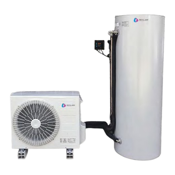
Heat pump Unit, Storage Tank with PTRV, Controller, Heat pump mounting legs. Figure 2: Photo of a Reclaim Energy heat pump hot water system. at 55 – 69% level depending on needs. More details regarding the 3.2 SYSTEM OPERATION The CO2 heat pump unit receives tank model i.d. -
Page 9: Technical Specifications
TECHNICAL SPECIFICATIONS This section summarizes the main technical specification of the Reclaim Energy heat pump hot water system. The fan, the evaporator, the compressor, the pump, HEAT PUMP 4.1 The dimension and section views of the heat pump and the water/refrigerant heat exchanger. The are displayed in Figure 3. The five main internal... - Page 10 HEAT PUMP UNIT: MODEL ID=EHPE-4540P PARAMETER UNIT VALUE 0.87 Power input * 5.24 Thermal output * 6.02 COP * CO2 (R744) Refrigerant ̊ C Output water temperature V/Hz 240V/50 Hz Power supply Amps 10.0 Current input (Max) Power input (Max) Noise level ̊...
- Page 11 1. The controller Module 4.2 CONTROLLER The controller is the electronic interface between the storage 2. Pre-fitted 230v power lead. tank and heat pump. The control unit has been designed to allow 3. Pre-fitted Temperature Sensor. home owners and installers to interface with the operations of 4. Pre-fitted RJ45 10 meter the unit to ensure it functions patch lead.
- Page 12 Table 5: Detail specification of the controller module. ITEM DESCRIPTION DETAILS Option 1: 24/7 operation Option 2 (off-peak 1 per CER method): 10 pm- 7 am Operational modes Option 3: 12 am- 6 am (6 hours) User selectable Option 4: 10 am- 4 pm Option 5: timer with two zones for customized operations One-off heating cycle (overwrite the operational mode and revert One-shot boost button User selectable back after completion)
-
Page 13: Installation Details
INSTALLATION DETAILS This section relates to the preparation and the installation proccess for the Reclaim Air-Source CO2 Heat Pump system. The installation of a Reclaim Energy air source heat 5.1 SITE INSPECTION AND INSTALLATION pump can only be completed by a licensed plumber... - Page 14 • When unpacking, take care to ensure that the components have been provided. Any concerns components are not damaged in the process. must be brought to the attention of Reclaim Energy immediately. • Avoid using sharp blades or knives as this can scratch the surfaces of the products.
- Page 15 Please note this is not supplied by Reclaim Energy but the installing plumber can consider installing a ring main system for hot water circulation.
- Page 16 B 50mm and longer C 150mm and longer 5.3.2 Mounting Note Reclaim Energy ASHP MUST be installed on the ground with mounting frames that is a Figure 13: A heat pump drain elbow plug supplied with heat pump unit. default supplied component OR on the wall with brackets.
- Page 17 5.3.4 REMOVING/ Remove ATTACHING THE PIPING Attach COVER Removal 1 Remove the screw 2 Remove the piping cover (Five areas) sliding downward. Attachment Screw 1 Fit the piping cover to the unit adjusting 5 tabs. Piping 2 Attach the piping cover sliding Cover upward and fix it with the screw.
- Page 18 The controller box is waterproof, but DO NOT 5.4 CONTROLLER Please note that this controller has 4 cable install the controller under the PTRV valve or grommets and glands as shown in Figure 17. The where there is a risk of water leaking. spare cable gland provided is not functional in this version of system.
- Page 19 3 Since the tank surface is curved, use the 5.4.1 HOW TO MOUNT THE CONTROLLER spacers provided using the 4 No. spacers and ON THE TANK WALL Using a Phillips head screwdriver remove the screws provided to mount the module to the skin modules top cover by loosening the four cover of the tank.
- Page 20 5.4.2 TERMINAL BLOCKS- PREWIRED Figure 20: Prewired POWER CABLE AND SENSOR CABLE power cable on As the connections are prewired, the installer terminal block 1 just needs to check if they are in place and tight (CON1). enough. The 230v power cable is prewired to the terminal block CON1, as shown in Figure 20. Check the connections and tighten if necessary. Check to ensure the cable gland the power cable passes through is tight.
- Page 21 Cold Inlet Heat Pump Unit COLD MAINS PLV 500 kPa Figure 23: Plumbing diagram of Reclaim Energy ASHP hot 600 kPa (Check with a certified local plumber - not mandatory water system. from system perspective.) 4. Do not put any restrictive valves such as check...
- Page 22 (isolation valve and check valve) and should • Four-Way Cross have a pressure limit of 500kPa. The set of mains line valves can be purchased as If the property does not have the cold pressure a kit from Reclaim Energy and provides the above inlet limited to 500 kPa (at the water meter), one components with insulating jackets to streamline the installation process. MUST be fitted at the hot water service cold supply...
- Page 23 IMPORTANT! Do not supply power to the controller or heat pump unit before conducting the proccess explained in section 5.5.3 and 5.5.4. Controller On/Off pulse wire (RJ 45 cable) 240v power cables Storage Tank On/Off pulse wire (RJ 45 cable) Heat Pump Unit Figure 26 Wiring diagram of Reclaim Energy ASHP hot water system. 23 - Owners Manual...
- Page 24 5.5.1.2 HEAT PUMP WATER Heat pump PCB display (where RJ45 PIPING INSTALLATION cable should be connected to) After removing the right side piping cover of heat pump unit, Heat pump GPO the heat pump cold (inlet) and hot (outlet) pipes (connection ports) will be accessible as shown in Figure 25.
- Page 25 Figure 30: How to connect RJ45 PATCH cable to heat pump display unit. CONNECT RJ45 Figure 31: Wiring of RJ45 cable from controller to the PCB display unit. RJ45 cable & connection to the PCB display unit 3. “88:88” and all LEDs turned on to check all 5.5.3 POWERING UP THE CONTROLLER FOR display LEDs are functional.
- Page 26 5.5.3.1 SETTING THE TIME OF DAY 5.5.4.1 FILLING OF THE SYSTEM WITH HOT 1. Press the Menu Button, “Menu” is displayed. WATER AND AIR PURGE THE HEAT PUMP UNIT 2. Press Temperature Button (move to next parameter), “TIME” is displayed. CAUTION! Make sure to complete the air purge before heating operation.
- Page 27 5.5.4.2 HOW TO RUN THE PURGE MODE 5.6 POST INSTALLATION INSPECTION ON THE CONTROLLER CHECKLIST To activate Purge Mode, perform the following steps: A licensed installer should check for the following before leaving the installation site. 1 Ensure the module is in the Normal Display mode, displaying either Time of day, or •...
- Page 28 CHECK LIST ITEMS CHECK GENERAL Water supply is in accordance with water quality standard. There is no leakage from the pipes. There is no flammable hazardous materials around the unit. There is no damage, deformation or contamination to any components. There is enough space for inspection / repair of each component? The floor below the tank/heat pump has been properly water proofed and is capable of supporting the component.
-
Page 29: Operational And Maintenance Details
OPERATION AND MAINTENANCE The following section covers user guides and information on the day to day operation and maintenance of the Air-Source CO2 Heat Pump system. 6.1 CONTROLLER LED ON - LED ON - SOLID FLASHING 6.1.1 DEFINITIONS AND CONTROL PHILOSOPHY Temperature Mode Power On... - Page 30 3.1.1.4 LEGIONELLA TIME CYCLE CHECK IMPORTANT! On the first activation (within a 24 For the effective elimination of Legionella, hour time cycle), the Heat Pump will run until the the system control will automatically heat the turn OFF temperature is reached, regardless of the temperature of 59 ̊ C at least once every 24 hours. turn OFF time setting.
- Page 31 this button. The temperature is displayed for 4 BOOST BUTTON: Press to switch Heat Pump into boost mode. The On seconds (Figure 34), then the currently selected Call LED will start flashing, indicating the heat pump user option is displayed for 4 seconds (Figure 34), has been turned on via Boost Mode. If inadvertently before reverting back to the tank temperature for pressed, boost mode can be turned off by pressing a remaining 12 seconds.
- Page 32 10 Use the Boost Button to increment the Time-ON 6.1.4 USER MENU There are three push buttons on the side of the UP, or the temperature button to decrement module. Each button has multi functions depending the Time-ON DOWN). The longer the button is on the menu level you are currently in. The menu pressed the faster the time will change.
- Page 33 8 The tank temperature can be displayed by pressing 6.1.6 POWERING UP THE MODULE the temperature button momentarily. “XXoC” will be (REPEAT TIMES) 1 “HP2d” is displayed, this is the current software displayed for 4 seconds, the set controller option version loaded.
- Page 34 ERROR CODE TABLE ERROR CODES APPEARANCE, PORTION, PARTS FIGURE/ ERROR METHOD OF CHECK TROUBLESHOOTING REMOTE SEEMED WRONG TABLE RESET CONTROL Sensor should be replaced if it is Outdoor temp. sensor Check the resistance value by tester. broken. Outdoor temp. Auto sensor error PCB(Main) PCB (Main) should be replaced.
- Page 35 PCB (Main) or HP unit Other than described above If the problem is not solved, HP unit shall be replaced. No detection of Please contact Reclaim Energy Support Improve the cause of problem, then Tank sensor Auto EG-8 tank sensor on: 1300 38 38 15 restart the HP unit.
- Page 36 • Check the controller status: (min) once per week for approximately 30 seconds from the lever on the and see if any error codes displayed. If the PTRV. Stand clear of PTRV discharge piping outlet. yellow light is flashing, call Reclaim Energy on 1300 38 38 15. • Check the tank anode (for glass-lined tanks only) WARNING! Ensure there are no open flames or every 3 years ignition sources close to the tank.
-
Page 37: Warranty
Reclaim Energy Controller and sensor lead 1 year Controller 850 kPa PTRV 1 year Valves Table 12: Component warranty table. * Reclaim Energy covers the labour for 6 years on heat pump unit and 1 year for other parts with capped service costs as per service schedule of rates being 2 hours labour maximum including travel up to 25km. Travel charge outside of this 25km range to be paid by customer. 37 - Owners Manual... - Page 38 3 To the extent that a claim falls under the ‘Parts Only’ Warranty Period, the Warranty covers 12 To the extent permitted by law, Reclaim Energy the repair and/or replacement of such failed shall not be liable under this Warranty for any component in domestic use free of charge.
- Page 39 23 Where the Reclaim Energy heat pump hot water component as outlined in Table 12 – Warranty system is installed in a position that does not Periods.
- Page 40 Total Hardness (CaCO3) 850 μS/cm Electrical Conductivity < 300 mg/L or ppm Chloride Min 6.5 to Max. 8.5 pH Level < 10 mg/L or ppm Magnesium < 150 mg/L or ppm Sodium < 1mg/L or ppm Iron < 200 mg/L or ppm Alkalinity (as CaCO3) < 25 mg/L or ppm Dissolved (free) CO2 Table 13 Water quality requirement for Reclaim Energy Hot Water Heat Pump Installation. 40 - Owners Manual...
- Page 41 Reclaim Energy shall replace or repair on a special equipment and/ or excessive labour, at the pro-rata basis set out in the scaling scale below: 41 - Owners Manual...
- Page 42 9. Year 15: Reclaim Energy 10%- Customer 90% Note that the % represents the proportion the customer (e) Product serial tag or other identification is defaced will pay based on the current Reclaim Energy price list or removed; for material and labor (where applicable). (f) Any operation exceeds the documented design limits of the system components or materials.
Need help?
Do you have a question about the REHP-CO2-160GL and is the answer not in the manual?
Questions and answers