
Related Manuals for ANK 300B


Summary of Contents for ANK 300B
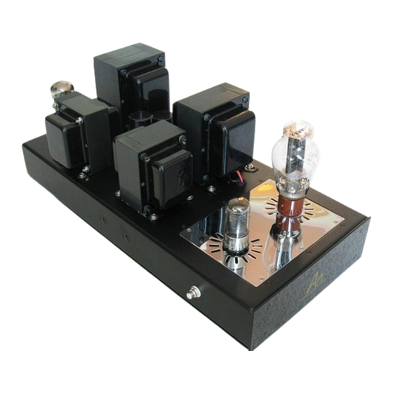
- Page 1 Interstage Monoblock 300B SET Amplifier Construction Manual Version 3.05, August 2019 audionotekits@rogers.com 1-613-822-7188...
-
Page 2: Table Of Contents
……………....………………………………………………….…… Installing the Hex Standoffs …........…………........…………… Section 3 — Installing the Transformers ..............… Overview ………………………………………………………………………………..…..….………..…….…… Installing the Mains Transformer ……………………………………..….…..….………..…….…… Installing the Choke ……………………………………………………………..…….………………..…….…… Installing the Interstage Transformer …………………………………………………………..…….…… Copyright © 2019 ANK Audio Kits www.AudioNoteKits.com audionotekits@rogers.com Page 2... - Page 3 Section 8 —Interstage Transformer Wiring .............. … Overview …………………………………………………………………………………..….………….…….…… Section 9 —Installing and Wiring the Rear Connectors ........… Overview …………………………………………………………………………………...….………..…….…… Installing the RCA Input Jack ………………………………………....…...….………..…….…… Wiring the RCA Input Jack ………………………………………....…..….…..……..…….…… Copyright © 2019 ANK Audio Kits www.AudioNoteKits.com audionotekits@rogers.com Page 3...
- Page 4 Cables …………………………………..………………………….…………………………………………….…...………… 13.3 Tube Rolling ……………………..………………………….…………………………………………….…...………… 13.3.1 5U4G ……………………..…………………..……….……………………..……………………...…………… 13.3.2 6SH7 ……………………..…………………..……….……………………..……………………...…………… 13.3.3 300B ……………………..…………………………………………………………………….…….…………… 13.4 Thanks ……………………..…………………………………………………..……………….………….………………….… Appendix ……………………………………………..……………………………………………………...……….……….…… Resistor Color Code Reference …………………………………………………………………….…..…….…… Mains Wiring for 240V …………………………………………………………………….…..………………….…… Copyright © 2019 ANK Audio Kits www.AudioNoteKits.com audionotekits@rogers.com Page 4...
-
Page 5: Section 1 - Introduction
Section 1 Introduction Thanks for purchasing the ANK Audio Kits Interstage Monoblock 300B SET Amplifier. Our goal is to provide you with the highest quality kit that you will build from scratch with these instructions. This is very high end and sophisticated piece of audio equipment that will surely become a showpiece of your sound system. -
Page 6: About Ank Audio Kits
As a result, ANK Audio Kits began offering this service for Level 4 and 5 products so that a significant investment in a kit could be turned into a work of art! Since ANK Audio Kits was born in 2004, over 2,500 kits have been shipped to customers worldwide. -
Page 7: Basic Operation Of The Amplifier
ANK Audio Kits and SET amplifiers go a long way back, right to the beginning in fact, with our Kit1 300B, which has had successive and successful anniversary editions. It's no surprise then that these 300B single and parallel SET monoblocks are simply awesome! A pair of these power amplifiers are a perfect mate for the Mentor pre-amplifier and a path to truly exceptional audio enjoyment. - Page 8 1:1 interstage transformer bifilar wound sitting on a very large core for superb bass response; high quality black Teflon 4- and 8-pin valve bases; and Audio Note (UK) hardwire tag strips. Copyright © 2019 ANK Audio Kits www.AudioNoteKits.com audionotekits@rogers.com...
-
Page 9: Schematic
From time to time revisions and upgrades to products result in circuit changes that are not always reflected in manuals. If you encounter any issues with how this schematic relates to your build that need clarifying, contact us at audionotekits@rogers.com. Copyright © 2019 ANK Audio Kits www.AudioNoteKits.com audionotekits@rogers.com Page 9... -
Page 10: Equipment
The solder should flow freely; if it’s forming balls then there is likely a problem with the tip, the temperature, or (sometimes) the surface. Feel free to contact us for help! For example, WBT-0800. Copyright © 2019 ANK Audio Kits www.AudioNoteKits.com audionotekits@rogers.com Page 10... -
Page 11: Components
That way of looking at things sometimes now no longer applies. Please be assured that all resistors supplied with ANK Audio Kits are rated at least per the specified wattage: in some cases, a higher than specified wattage may be supplied. -
Page 12: Diodes
This makes for easy soldering to a PCB, an RCA connector, or a transformer terminal. So it's a good idea to practice this a little before starting the kit. Copyright © 2019 ANK Audio Kits www.AudioNoteKits.com audionotekits@rogers.com... -
Page 13: Wire Color
1.5.10 Optional Finishing Touches From time to time we get asked about some of the build details of the ANK Finished Products that you can see in the pictures in the "Assembled Kits Gallery!" (https://ankits.smugmug.com/) on our website. -
Page 14: Organization Of This Manual
6. Filament Supply Board Interwiring 7. Front Insert Plate Wiring 8. Interstage Transformer Wiring 9. Installing and Wiring the Rear Connectors 10. Wiring Check Lists 11. Testing 12. Finishing Touches 13. Final Thoughts Appendix Copyright © 2019 ANK Audio Kits www.AudioNoteKits.com audionotekits@rogers.com Page 14... - Page 15 Top Side Bottom Side Copyright © 2019 ANK Audio Kits www.AudioNoteKits.com audionotekits@rogers.com Page 15...
- Page 16 Copyright © 2019 ANK Audio Kits www.AudioNoteKits.com audionotekits@rogers.com...
-
Page 17: Electrical Safety Warning
There are sufficient voltages in this kit to give you a very nasty and harmful shock, so be careful when powering on, debugging, and probing around. Please contact ANK Audio Kits via phone or email (audionotekits@rogers.com) to discuss any precautions necessary when building the kit if you feel unsure about what you are doing at any stage of the build. -
Page 18: Section 2 - Mechanical Assembly
Let's start with the chassis and install the: rubber grommets 35mm clamps 8-pin valve base ceramic posts IEC and Rocker Switch Mills 40R resistor Hex standoffs Copyright © 2019 ANK Audio Kits www.AudioNoteKits.com audionotekits@rogers.com Page 18... -
Page 19: Installing The Rubber Grommets
Be careful not to use a sharp object to push them in – just use Install the grommets in chassis. your hands and take your time. (You can push them from the underside of the chassis, if you find that easier.) Copyright © 2019 ANK Audio Kits www.AudioNoteKits.com audionotekits@rogers.com Page 19... -
Page 20: Installing The Clamps
M3 10m black flat or countersunk screws. Here is the view from the underside of the chassis… … and the view from the top of the chassis: Copyright © 2019 ANK Audio Kits www.AudioNoteKits.com audionotekits@rogers.com... -
Page 21: Installing The Valve Base
Use the Black ring on the underside of the chassis to secure the valve base into position that the notch on the inside of the valve base is pointing toward the front of the chassis. Copyright © 2019 ANK Audio Kits www.AudioNoteKits.com audionotekits@rogers.com... -
Page 22: Installing The Ceramic Posts
The next picture shows the 10-position ceramic posts mounted into position. Use 4 6mm steel M3 countersunk (flat) screws to mount the posts on the underside of the chassis, as shown. Here are the posts actually mounted: Copyright © 2019 ANK Audio Kits www.AudioNoteKits.com audionotekits@rogers.com Page 22... -
Page 23: Installing The Iec Socket And Rocker Switch
Of course, the orientation isn't critical as long as the wiring is done correctly, but the orientation that is shown is what you'll see in the rest of the pictures and graphics in the manual so it's probably easier just to do it that way. Copyright © 2019 ANK Audio Kits www.AudioNoteKits.com audionotekits@rogers.com... -
Page 24: Installing The Mills Resistor
Installing the Mills Resistor Position the 40 ohm Gold Mills resistor as shown below and secure with 2 x 10mm Black counter sunk screws from top of chassis. Copyright © 2019 ANK Audio Kits www.AudioNoteKits.com audionotekits@rogers.com Page 24... -
Page 25: Installing The Hex Standoffs
"FILAMENT." These 4 hex standoffs are located to the right of 35mm clamps; Use these standoffs and screws and install them in the chassis, as shown below: Here's another view, from the top of the chassis: Copyright © 2019 ANK Audio Kits www.AudioNoteKits.com audionotekits@rogers.com... - Page 26 Congratulations! The chassis is now prepared for the rest of the build. Time for a break! Copyright © 2019 ANK Audio Kits www.AudioNoteKits.com audionotekits@rogers.com Page 26...
-
Page 27: Section 3 - Installing The Transformers
OP-300 SET 300B Output transformer) It's a good idea to read through this whole section prior to starting to so you have a good idea of what is coming! Copyright © 2019 ANK Audio Kits www.AudioNoteKits.com audionotekits@rogers.com Page 27... -
Page 28: Installing The Mains Transformer
Position the transformer upside down and beside the chassis, as shown above. Lay down the two rubber strips from your kit bag onto the chassis. Start feeding the wires through the chassis as shown below. Copyright © 2019 ANK Audio Kits www.AudioNoteKits.com audionotekits@rogers.com... - Page 29 Once all the wires are fed through you can use a cloth to wipe off any excess WD-40 spray. Here's a view from the underside: Once you have fed the wires through (loosely) you can stand the chassis on its side: Copyright © 2019 ANK Audio Kits www.AudioNoteKits.com audionotekits@rogers.com Page 29...
- Page 30 Copyright © 2019 ANK Audio Kits www.AudioNoteKits.com audionotekits@rogers.com...
- Page 31 The washer goes on the top of the chassis and the M4 serrated washer on the underside of the chassis. Here a view from the underside Copyright © 2019 ANK Audio Kits www.AudioNoteKits.com audionotekits@rogers.com Page 31...
- Page 32 The picture below shows the position that we will be working on for most of the kit. Well done! Things should get a bit easier from this point on. Copyright © 2019 ANK Audio Kits www.AudioNoteKits.com audionotekits@rogers.com Page 32...
-
Page 33: Installing The Choke
Feed the two Black wires through the grommet hole and then use the M4 Pan 10mm screws to secure it into place. Below you can see the Choke mounted and the next transformer being readied. Copyright © 2019 ANK Audio Kits www.AudioNoteKits.com audionotekits@rogers.com... -
Page 34: Installing The Interstage Transformer
The IN-500 Interstage Transformer is the next to be installed. Feed the wires through the grommet hole as shown and then use the M4 Pan 10mm screws to secure it into place. Copyright © 2019 ANK Audio Kits www.AudioNoteKits.com audionotekits@rogers.com... -
Page 35: Installing The Power Supply Capacitors
This 4-pole electrolytic capacitor has an input (IN) and an output (OUT), each with a POSITIVE and NEGATIVE lead. To see how it is connected in the circuit, have a look at the Power Supply schematic. Copyright © 2019 ANK Audio Kits www.AudioNoteKits.com audionotekits@rogers.com... - Page 36 Here is the bottom view; line them up as you see in the picture and the wiring graphic below. The middle capacitor is non-polarized. Copyright © 2019 ANK Audio Kits www.AudioNoteKits.com audionotekits@rogers.com Page 36...
-
Page 37: Installing The Output Transformer
Green, Blue, and Purple output (Secondary) wires want to be closest to the capacitors. Here is the position of the Output Transformer: Secure the Output Transformer as shown above. Phew! Congratulations on completing the Transformer installation section. Copyright © 2019 ANK Audio Kits www.AudioNoteKits.com audionotekits@rogers.com Page 37... - Page 38 Another cup? Copyright © 2019 ANK Audio Kits www.AudioNoteKits.com audionotekits@rogers.com Page 38...
-
Page 39: Section 4 - Power Supply Wiring
As we move forward with the wiring, there will be pictures and graphics in the manual to guide you. There are also higher definition pictures and graphics you can refer to in the separate Interstage Wiring Guide in .pdf format on your disk. Copyright © 2019 ANK Audio Kits www.AudioNoteKits.com audionotekits@rogers.com... - Page 40 Here's a picture of the underside of a nice parallel Legend build: there are circuit differences between this and the Interstage 300B, but there's enough similarity to make it worth looking at. Note again how to wires are grouped and cable-tied, how neatly the capacitors are attached to the tag strip, etc.
- Page 41 So, for example, twist together the Orange wires of the HT, the Grey wires of the 6SH7 Filament, the center tap (CT) wires, etc. This will help keep us organized as we proceed. Copyright © 2019 ANK Audio Kits www.AudioNoteKits.com audionotekits@rogers.com...
-
Page 42: Preparing The Chassis Ground
Extend the wire past the Chassis Ground, then strip and tin the wire. Add a lug to the tinned wire and then solder the lug onto the wire. Do this by adding solder through the front of the lug, as shown below. Copyright © 2019 ANK Audio Kits www.AudioNoteKits.com audionotekits@rogers.com... - Page 43 Power Supply Ground. Add a nut and gently tighten. We may be moving the wires a little later so there's no need to tighten it too much! Copyright © 2019 ANK Audio Kits www.AudioNoteKits.com audionotekits@rogers.com Page 43...
- Page 44 Here's what it should look like: Copyright © 2019 ANK Audio Kits www.AudioNoteKits.com audionotekits@rogers.com Page 44...
-
Page 45: Wiring The Iec, Rocker Switch And Mains
We've provided a number of pre-made cables and parts for this section to make it easier and neater: 2 crimps Heatshrink Red/Black twisted cable with crimps For 120 V operation, take the twisted White/White-Grey and twisted Black/Black-Grey pairs of wires coming from the Mains. Copyright © 2019 ANK Audio Kits www.AudioNoteKits.com audionotekits@rogers.com Page 45... - Page 46 Rocker Switch, as shown in the graphic above. Take the prepared Red/Black twisted cable and complete the connections as shown in the graphic. Leave about 5 inches of twisted White/White-Grey wire, at least. Copyright © 2019 ANK Audio Kits www.AudioNoteKits.com audionotekits@rogers.com Page 46...
-
Page 47: Wiring The 8-Pin Valve Base
Let's begin by wiring up the 8-pin valve base. Tie off the Red pair of wires. We won't be using them; they're used for the parallel 300B build. Take the Orange twisted pair and put heatshrink on the ends so that they do not interfere with anything else. -
Page 48: Wiring The Ceramic Post Resistors And Capacitors
In any event, if you get to the end of this section and you find anything still not soldered, you should solder it. And, please let us know if we've missed something or messed up, so we can update the manual. Thanks. Copyright © 2019 ANK Audio Kits www.AudioNoteKits.com audionotekits@rogers.com... - Page 49 47K post unsoldered for the moment. Connect and solder the left end of the 100R resistor to the Chassis Ground using the Green wire that has one end attached to the Chassis Ground and one end unconnected Copyright © 2019 ANK Audio Kits www.AudioNoteKits.com audionotekits@rogers.com...
-
Page 50: Initial Mains Secondary Wiring
30uf 600V chassis mounted capacitor, as shown above. Don't solder this yet. Connect the Blue/White wire from the Mains Secondary to the left end of the 47K resistor and solder the connections, as shown above. Copyright © 2019 ANK Audio Kits www.AudioNoteKits.com audionotekits@rogers.com... -
Page 51: Wiring The Choke
A choke is basically one long piece of wire wrapped around a core in order to slow down any AC movement. They are used in power supplies to smooth out the DC that is generated by the rectifier tube. Copyright © 2019 ANK Audio Kits www.AudioNoteKits.com audionotekits@rogers.com... - Page 52 Copyright © 2019 ANK Audio Kits www.AudioNoteKits.com audionotekits@rogers.com Page 52...
-
Page 53: Additional Capacitor Wiring
It can be a challenge to do this complex wiring neatly, but here's a picture of how it can look if you spend the time and show the patience necessary to achieve a really nice result: Copyright © 2019 ANK Audio Kits www.AudioNoteKits.com audionotekits@rogers.com... - Page 54 Output transformer grommet will be connected later.) Before you go any farther, we strongly recommend that you go back to the beginning of the Power Supply section, and check every connection carefully! Copyright © 2019 ANK Audio Kits www.AudioNoteKits.com audionotekits@rogers.com...
-
Page 55: Section 5 -Filament Supply Board Installation
Overview In this section we will be populating the Filament Supply PCB. This board will take the 7V AC voltage from the Mains Secondary and DC regulate it down to 5V which will be used to supply the 300B filaments. -
Page 56: Parts List
2–3 mm spacer: this will still let you solder while ensuring that the resistor is not pressing against the board. Copyright © 2019 ANK Audio Kits www.AudioNoteKits.com audionotekits@rogers.com... -
Page 57: Installing The Capacitors
POSITIVE side. Be sure to align the capacitors correctly into position. Install the 2 4700uf 16V Electrolytic Capacitors at C1 and C2. Install the 10uf 16V Electrolytic Capacitor at C5. Copyright © 2019 ANK Audio Kits www.AudioNoteKits.com audionotekits@rogers.com... -
Page 58: Installing The Bridge Rectifier
DC filament voltages. You'll see a notch on the Bridge Rectifier (part number: KBU6J): match the notch with the '+' (POSITIVE) stencil on the board. Install the KBU6J Bridge Rectifier at B1. Copyright © 2019 ANK Audio Kits www.AudioNoteKits.com audionotekits@rogers.com... -
Page 59: Installing The Regulator
Solder the 3-pin regulator and the heatsink from underneath the board. Once the Filament Supply board is ready you can position in the chassis. Don't attach it yet as we will be wiring to the board soon! Copyright © 2019 ANK Audio Kits www.AudioNoteKits.com audionotekits@rogers.com... -
Page 60: Section 6 -Filament Supply Board Interwiring
In this section we'll connect two wires from the Mains Secondary to the AC inputs on the Filament Supply board. These supply the 7V needed by the 300B tube. We recommend inserting the wires from underneath the board, soldering on the underside and the top, then cutting off the excess wire. - Page 61 Connect one end of a Red wire to the DC–1 tab, as shown below. Connect one end of a Black wire to the Gnd tab, as shown below. This completes the Filament Supply Board Interwiring section! Copyright © 2019 ANK Audio Kits www.AudioNoteKits.com audionotekits@rogers.com...
-
Page 62: Section 7 - Front Insert Plate Wiring
8-position Tag Strip Let's begin by installing the valve bases (the 6SH7 and 300B positioning is up to you). You can work on the insert plate outside of the Monoblocks and then when we get to a certain point we will install into the chassis. -
Page 63: Installing The Resistors
We're going to label the pin that is directly connect to the power resistors as the Cathode. That will mean that the Cathode is Pin 4. It's unusual and has to do with the circuit design. Copyright © 2019 ANK Audio Kits www.AudioNoteKits.com audionotekits@rogers.com... -
Page 64: Installing The Capacitors
Connect the other (POSITIVE) lead to Tag E. Connect the POSITIVE lead of the 220uf 100V Elna Cerafine Electrolytic capacitor to Tag G. Connect the other (NEGATIVE) lead to Tag H. Copyright © 2019 ANK Audio Kits www.AudioNoteKits.com audionotekits@rogers.com Page 64... -
Page 65: Additional Wiring
RCA jack and the remaining interstage components. And we'll complete some additional the Front Insert Panel interstage wiring by adding several Ground and filament wires, and another connection to the 6SH7. Referencing the graphic below, Copyright © 2019 ANK Audio Kits www.AudioNoteKits.com audionotekits@rogers.com Page 65... - Page 66 Connect a Black wire from Pin 3 on the 6SH7 to Tag E. And, finally, referencing the graphic below, Connect a Black 300B Ground wire coming from position 7/8/9 of the ceramic posts to Tag H. Connect the Green (or Black) 6SH7 Ground wire coming from position 7/8/9 of the ceramic posts to Tag D.
-
Page 67: Section 8 -Interstage Transformer Wiring
Connect the White wire coming from the Interstage transformer grommet to Tag C on the tag strip. Connect the Blue wire coming from the Interstage transformer grommet to Tag A on the tag strip. Copyright © 2019 ANK Audio Kits www.AudioNoteKits.com audionotekits@rogers.com... -
Page 68: Section 9 -Installing And Wiring The Rear Connectors
Tighten the jack ; it'll make soldering much easier in that position. Make sure everything is snug and well tightened. Copyright © 2019 ANK Audio Kits www.AudioNoteKits.com audionotekits@rogers.com Page 68... -
Page 69: Wiring The Rca Input Jack
100K 2W AN Tantalum Resistor 1K 2W AN Tantalum Resistor 330R 1/2W AN Tantalum Resistor 100R 2W AN Tantalum Resistor Now we'll add the input resistors, as shown in the following graphic: Copyright © 2019 ANK Audio Kits www.AudioNoteKits.com audionotekits@rogers.com Page 69... - Page 70 Connect the other end of the 100K resistor to the Ground of the RCA jack and to Tag D. Connect a 330R 1/2W resistor from pin 3 (where the Black wire to Tag E is already connected) of the 6SH7 to Tag D. Copyright © 2019 ANK Audio Kits www.AudioNoteKits.com audionotekits@rogers.com...
-
Page 71: Installing The Speaker Posts
Connect the Blue wire to the Red speaker post. Connect the Green wire to the Black speaker post. Cut the end of the Purple wire cleanly and cover it with a small plastic wire connector. Copyright © 2019 ANK Audio Kits www.AudioNoteKits.com audionotekits@rogers.com... -
Page 72: Section 10 -Wiring Check Lists
Orange filament wire from Mains Secondary Pin 5 Not connected Pin 6 Orange filament wire from Mains Secondary Pin 7 Not connected Pin 8 Brown filament wire from Mains Secondary Copyright © 2019 ANK Audio Kits www.AudioNoteKits.com audionotekits@rogers.com Page 72... - Page 73 RCA Ground Tag E 470uf 16V POSITIVE Black Wire to 6SH7 Pin 3 Tag F 1K0 resistor to 300B Pin 3 Wire to Tag C Tag G 220uf 100V POSITIVE Black wire to 300B Pin 4 2 x 1K5 resistors...
- Page 74 Black wire to NEGATIVE of NEGATIVE of 10uf 160V Position 9 Position 8 100+100uf capacitor capacitor Black wire to NEGATIVE of Position 10 100R resistor output (OUT) section of the 103J capacitor 220uf capacitor Copyright © 2019 ANK Audio Kits www.AudioNoteKits.com audionotekits@rogers.com Page 74...
-
Page 75: Section 11 - Testing
Make some basic DC measurements: for example, checking the 5V filaments of the 300B. Install the 6SH7 and the 300B, then power on to make sure that the 300B glows. Install the 5U4G rectifier and measure a number of key AC and DC voltages. -
Page 76: Installing The Fuse
Turn the amplifier on. If the fuse does not blow, continue to the next step. If it does, jump ahead to "Debugging." Turn the amplifier off. The picture is from a different build, but it's the same procedure. Copyright © 2019 ANK Audio Kits www.AudioNoteKits.com audionotekits@rogers.com... -
Page 77: Initial Tests
Red lead can be positioned somewhere else in the amplifier to get a resistance reading. The picture is from an earlier variant of the amplifier, but the Chassis Ground hasn't moved. Copyright © 2019 ANK Audio Kits www.AudioNoteKits.com audionotekits@rogers.com... -
Page 78: First Power-Up
Follow the turn-on procedure carefully. DO NOT AT ANY TIME ONLY INSTALL THE 5U4G TUBE WITHOUT ANY OTHER TUBES (SUCH AS THE 300B) INSTALLED. The reason for this is that the 5U4G tube is counting on having a specific load to drive. If the 5U4G is used without other tubes installed then the amplifier will 'see' significantly higher DC voltages (close to 600V!), which can overextend the Power Supply capacitors. -
Page 79: Voltage Tests
Turn the amplifier on. Let’s check the 5V DC on the filament pins (Pins 1 and 4) of the 300B: these are the two 'fat' pins nearest the sides of the chassis. Multimeter Setting... - Page 80 400V ± 5% The first measurement is the HT voltage on the Anode (Pin 2) of the 300B: the Anode of the 300B is the pin with a Red wire connected to it from the Output transformer. It's a good idea to get your schematic out and check the location that you are measuring (Pin 2).
-
Page 81: 6Sh7 Voltage
DC. Next, measure the voltage at input to the 15K resistors: we should see 440V. Multimeter Setting Black Lead Red Lead Approximate Reading Chassis Ground Top right ceramic post 166V Chassis Ground Top left ceramic post 302V Chassis Ground 15K resistors 'input' 440V Copyright © 2019 ANK Audio Kits www.AudioNoteKits.com audionotekits@rogers.com Page 81... -
Page 82: Sound Check
Finally, let's check two key AC voltages on the rectifier (5U4G). These are the filament voltages for the 6SH7 and the 300B. Since the maximum voltage on many multimeters is 600V, we'll measure the AC voltage for each pin (4 and 6) referenced to the Chassis Ground. For the 5V measurement, you can simply position the probes as shown: one on Pin 2 and one on Pin 8 (the orientation doesn't matter). -
Page 83: Debugging
Make sure that your speakers are connected. Recheck the wiring in the Power Supply and Front Insert Plate. If that doesn't fix things, contact ANK Audio Kits at audionotekits@rogers.com. We'll figure things out. Please have a few telling digital pictures ready to share with us. -
Page 84: Section 12 - Finishing Touches
Glue or attach (with some Blu Tack) the LED holder to the front panel so that the LED protrudes through the designated hole, as shown below: 12.3 Installing the Chassis Top Install the chassis top using the provided hardware. Copyright © 2019 ANK Audio Kits www.AudioNoteKits.com audionotekits@rogers.com Page 84... -
Page 85: Section 13 - Final Thoughts
13.2 Cables In our experience, a high quality power cable and good interconnects should make a noticeable improvement to the sound. Copyright © 2019 ANK Audio Kits www.AudioNoteKits.com audionotekits@rogers.com Page 85... -
Page 86: Tube Rolling
13.3 Tube Rolling We feel that the sound of the ANK Audio Kits Interstage Monoblock 300B SET Amplifier is truly sublime and that is destined to become a popular kit. It provides a highly detailed and transparent presentation with gorgeous sonics. Rolling some quality new production tubes and/or some nice NOS tubes will allow you to tailor the sound to your particular preferences. -
Page 87: Thanks
13.4 Thanks Thank you for investing in the ANK Audio Kits Interstage Monoblock 300B SET Amplifier and congratulations on working your way through the build. The manual is new and we would welcome your feedback. Please email us at audionotekits@rogers.com and let us know how everything went: were there any errors in the manual or instructions, parts lists, etc.? Your ideas regarding greater... -
Page 88: Appendix
Appendix Copyright © 2019 ANK Audio Kits www.AudioNoteKits.com audionotekits@rogers.com Page 88... - Page 89 You can also find an 'Interactive Resistor Color Code Calculator' on our website (available from the Links page). Copyright © 2019 ANK Audio Kits www.AudioNoteKits.com audionotekits@rogers.com Page 89...
-
Page 90: Mains Wiring For 240V
Mains Wiring for 240V Copyright © 2019 ANK Audio Kits www.AudioNoteKits.com audionotekits@rogers.com Page 90...
Need help?
Do you have a question about the 300B and is the answer not in the manual?
Questions and answers