Table of Contents
Advertisement
Advertisement
Table of Contents

Related Manuals for LockMaster LM901


Summary of Contents for LockMaster LM901
-
Page 2: Table Of Contents
Table of Contents Safety Installation Information ………………………………………..…………………………………..2-3 Dual Gate Opener Parts List (902) …………………………….…………………………………..……….….4 Single Gate Opener Parts List (901) …………….…………….…………………………………..……….….5 Optional Accessories Parts List………...………………………….…………...…………………..…….…….6 Technical Specifications & Features ………………………………..…………………...……….…………..7 Installation Overview ………………………………………………….…………………...……………….…8-9 Preparation for Installation…………………………………………………..………………………..….… 9-10 Determining the Position of Mounting Hardware……………………….…………………..……..……..10-12 Installing the Mounting Hardware……………..………………………………………..………..………. -
Page 3: Safety Installation Information
Safety Installation Information 1. READ and FOLLOW all instruction. 2. The gate opener is intended for use with Class I vehicular swing gates. Class I denotes a vehicular gate opener (or system) dwellings, or a garage or parking area associated therewith. - Page 4 11. Controls intended to be used to reset an operator after 2 sequential activations of the entrapment protection device or devices must be located in the line of sight of the gate, or easily accessible controls shall have a security feature to prevent unauthorized use. Never allow anyone to hang on or ride the gate during the entire travel of the gate.
-
Page 5: Dual Gate Opener Parts List (902)
Dual Gate Opener Parts List(902) Opener and Mounting Hardware... -
Page 6: Single Gate Opener Parts List (901)
Single Gate Opener Parts List(901) Opener and Mounting Hardware REV 09a... -
Page 7: Optional Accessories Parts List
Optional Accessories Parts List Tools Needed: ·Power Drill ·Tape Measure ·Open End Wrenches — 14# &17# or Adjustable Wrenches ·Wire Strippers ·C-Clamps — small, medium, and large ·Level ·Hacksaw or Heavy Duty Bolt Cutters ·Phillips Screwdriver ·An extra person will be helpful... -
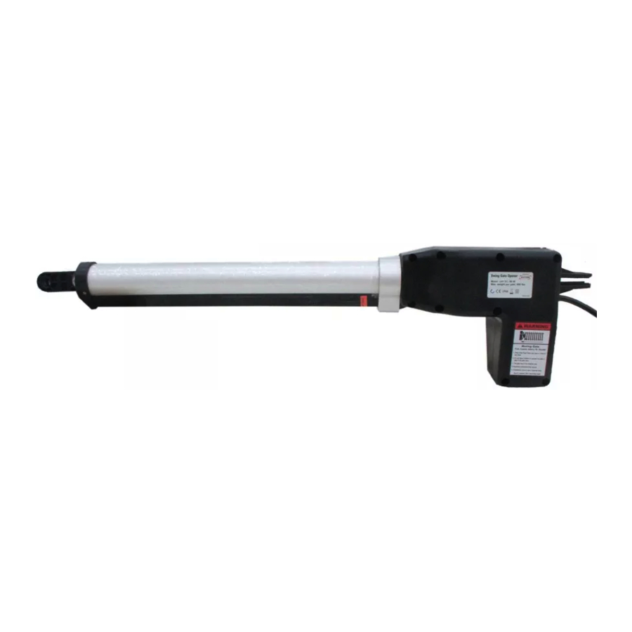
Page 8: Technical Specifications & Features
Technical Specifications & Features Specifications: ·Input: 230V/50Hz or 120V/60Hz ·Motor voltage: 24VDC ·Power: 80W each actuator ·Current: 3A ·Actuator arm speed: 16mm/s ·Max. Actuator arm travel: 385mm ·Max. Weight of the gate: 300kg ·Max. Width of the gate: 3m ·Ambient Temperature: -20℃~ +50℃ (-4° F to 122° F) ·Protection class:IP44 Features: ·Soft start... -
Page 10: Preparation For Installation
Preparation for Installation The proper position of the post brackets is a decisive factor to the efficiency and leverage of the gate opener. The distance (usually it is 2.5cm /1 inch or more) between the gate opener and the gate is also determined by the proper position of the post brackets. -
Page 11: Determining The Position Of Mounting Hardware
Both round and square post can be used because of the curved design of the post brackets. When mounting the post brackets, use bolts long enough to pass through the entire post. When mounting the post brackets to wooden posts, a larger-size washer or metal plate should be used between the bolts and the wood post to ensure the stability of the fastening hardware when thrust is used. - Page 12 Step 2 Attach the gate bracket and post bracket assembly to the opener by inserting a clevis pin. Secure the clevis pins using the hairpin clips. Step 3 With the gate in their desired open positions (from 0° to 100° from the gate’s closed position) and with the opener in their retracted positions, place the opener with the gate bracket and post bracket assembly on the gate post and the gate.
-
Page 13: Installing The Mounting Hardware
Installing the Mounting Hardware Step 5 Sign the bolt-hole point on the gate bracket and gate. Do this by placing a punch or a sign in the middle of each bolt slot on the post bracket assemblies and the gate bracket. It allows slight adjustments to the post bracket. -
Page 14: Installation Of The Opener
Step 8 Attach the gate brackets to each gate by inserting two M10 x 75 bolts through the gate brackets and the drilled holes in the gates. Fasten each bolt with one ¢10 lock washer, and one ¢10 nut. Step 9 Cut all parts of bolt which is extending beyond the tightened nuts by saw. -
Page 15: Mounting The Control Box
Mounting the Control Box Step 1 To install the control box use the deck screws (not provided). Ensure the control box is installed in a secure surface and at least 100 cm (40 inches) above the ground to protect it from rain, snow, etc. - Page 16 The cables listed from left to right are as follows: 2-core power cable; motor 1, 5-core cable; motor 2, 5-core cable; alarm lamp 2-core cable; battery 2-core cable; push button 2-core cable; photocell two 2-core cables NOTE: Only motor cables are provided. Other cables are subject to site installation requirement. CAUTION: Make sure the cable outlet hole in the Control Box is always down during so as to drain off the water.
-
Page 17: Connecting Opener Power Cables
Connecting Opener Power Cables Gate Opener 1 Step 1 Insert the stripped cable wires into the appropriate terminals on the opener terminals block. The red thick wire should be inserted into the MOTOR1+ terminal, the black thick wire into MOTOR1-, the red wire into ULT1, the black wire into COM, and the yellow wire into DLT1 terminal. -
Page 18: Wiring Diagram
Push Button (optional) Step 6 The red wire should be inserted into either O/S/C terminal, the white wire into the other one. Wiring Diagram Control Board Settings 1. Check again for completed and correct assembly of your swing gate opener and gate. Plug the Power Grounded Cord into the nearest AC outlet. - Page 19 3. Master/Slave Gate Set When Digital Display indicates “P2”, the gate opener is on the Master/Slave Gate Setting. Press the “INC” and “DEC” Buttons respectively to follow modes: “01” shown in Digital Display, which means Gate Opener 1 (right-hand side) as Master one “10”...
- Page 20 6-a Adjust Stall Force of Gate Opener 1 Now we adjust the stall force of gate 1 The stall force of gate opener1 is adjusted by pressing “INC” and “DEC” Buttons respectively. The Digital Display will show “1” –“9” which indicates the stall force level.”1” is the minimum force, and “9” is the maximum force.
- Page 21 9. Set the automatic closing time: When the Digital Display indicates “PA”, the gate opener enters into the setting the automatic closing time mode. Press and release the “INC” or “DEC” Buttons, the Digital Display will show a “1”-“9” which indicates the current automatic closing time.
-
Page 22: Indicate Illustration On Digital Display When Gate Opener Is Running
Indicate Illustration on the Digital Display When Gate Opener is Running The left mark on Digital Display symbolizes motor of gate opener 1 when the gate opener is running. The right mark on Digital Display symbolizes motor of gate opener 2. When the motor is run to gate -open direction or gate -close direction, the mark on Digital Display indicates “n”... -
Page 23: How To Operate
Pull Gate 2 to its fully open position. Use a cross point screwdriver to unscrew Limit Switch C and slide it to the desired position. Then fix the Limit Switch C. Pull Gate 2 to its fully closed position. Use a cross point screwdriver to unscrew Limit Switch D and slide it to the desired position. -
Page 24: Accessories Connection
Accessories Connection (Optional) There is connection wire Terminal on the PCB board in the control box. The function is as follows: (1)BAT(+) BAT(-) for back up battery The user can connect backup battery (optional) by both BAT (+) and BAT (-) terminals. By installing a 24V/5AH battery (optional), the SWING GATE OPENER will be possible to carry out approx. -
Page 25: Installation For Push-To-Open Gates
NOTE: The positive terminal of the solar panel should be connected to the positive terminal of the battery and vice versa. The bigger capacity of the batteries is, the longer the system will operate in cloudy days. The solar energy conversion efficiency may vary with installation places and weather conditions. Install the solar panel in open area clear of obstructions such as tall trees and buildings which probably block the sunlight. - Page 26 Step 3 With the gate in closed positions and with the opener in their retracted positions, place the opener with the gate bracket and post bracket assembly on to the gate post and the gate. Position the gate bracket and the post bracket assembly so that the gate opener is level with the horizontal cross member of the gate.
-
Page 27: Maintenance
Maintenance Warning: Disconnect power before servicing. 1. Using a clean, dry cloth, wipe the gate opener shaft, and then apply a silicone spray to reduce its friction. In cold climates where temperatures reach 1° C (30° F) or less, spray silicone on the actuator arm every 4-6 weeks to prevent freeze up. -
Page 28: Quick-Setting Guide
• Check that wires to the limit switch are not shorted. • Ensure that the motor cable is away from sources of electrical interference, such as electric fences, power lines etc. 6. Gate opens, closes or stops on its own •Ensure that the key for manual release is in the lock position. - Page 29 REV 09a...
- Page 30 REV 09a...
- Page 32 FCC Note: The manufacturer is not responsible for any radio or TV interference caused by unauthorized modifications to this equipment. Such modifications could void the user’s authority to operate the equipment. This device complies with Part 15 of the FCC Rules. Operation is subject to the following two conditions: 1.
Need help?
Do you have a question about the LM901 and is the answer not in the manual?
Questions and answers
Hi my remote for lm901 won’t open my ****
The LockMaster LM901 remote may not open your door if the remote control transmitter and the gate opener receiver are not programmed to a matching code. To resolve this, you need to program the remote to the opener:
1. Ensure the Digital Display indicates "PC."
2. Press and release the "INC" button, and the Digital Display will indicate "Ln."
3. Press the key on the remote control twice.
4. Wait for "PC" to display on the Digital Display after "Ln" flashes for 4 seconds, confirming the opener has learned the code.
Repeat these steps if necessary for additional remotes.
This answer is automatically generated
My lockmaster lm902 after closing.approx 1 min after it will automatically open.
"..unscrew Limit Switch B and slide it to the desired position. Then fix the Limit Switch B." The position to what? What is desired position? How to change position of magnetic ring?
The desired position for Limit Switch B on the LockMaster LM901 is at the fully closed position of Gate 1. To set it, pull Gate 1 to its fully closed position, use a cross point screwdriver to unscrew Limit Switch B, slide it to the desired position, and then fix it in place.
The magnetic ring must always be placed between Limit Switch A and Limit Switch B.
This answer is automatically generated
How do I problem the controller to leave the gate open until I use the remote to close?