Table of Contents
Advertisement
KBM
-18
®
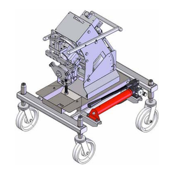
PORTABLE PLATE EDGE
BEVELLING MACHINE
Adjustable bevel head produces
bevel angles from 22.5º through 55º
Supplied with angle bevel pin for 30º
Other bevel angle pins are available
upon request.
NOTE: Machine shipped with the 30º
bevel pin in place.
PARTS LIST
&
OPERATING INSTRUCTIONS
Website: www.gullco.com
Distributed by:
Revised: May 1, 2018
GD-046
Advertisement
Table of Contents

Related Manuals for GULLCO KBM-18


Summary of Contents for GULLCO KBM-18
- Page 1 22.5º through 55º Supplied with angle bevel pin for 30º Other bevel angle pins are available upon request. NOTE: Machine shipped with the 30º bevel pin in place. PARTS LIST & OPERATING INSTRUCTIONS Website: www.gullco.com Distributed by: Revised: May 1, 2018 GD-046...
-
Page 3: Table Of Contents
READ BEFORE USING THE KBM®-18 BEVELLER IMPORTANT NOTES: All machine operators must be familiar with the Safety Instructions on pages 1 & 2 of this manual before attempting to use the KBM -18 Beveller. ® The machine must be set in accordance with the “Bevel Setting” section of this manual (pages 10 - 15) prior to bevelling or machine / cutter damage... - Page 4 PREPARATION FOR SELF PROPELLED OPERATION ................. 22 PREPARATION FOR BENCH OPERATION .................... 23 BEVEL OPERATION ..........................24 INTERRUPTED MATERIAL FEED ......................25 BEVELLING FLAME CUT STEEL PLATES ..................... 26 BEVELLING OF TOUGHER MATERIALS ....................26 ...
-
Page 5: Safety Instructions
The start/stop switch should always be accessible to the operator. This machine must not be operated in highly explosive environments. This label is attached to the Gullco bevelling machine and its intent is to instruct all those concerned to... - Page 6 SAFETY INSTRUCTIONS CONTINUED A careless operator invites troubles, and failure to follow safety practices may cause serious injury or even death. Additional important safety precautions are given in the following: Electrical Shock Prevention Do not use this equipment in damp or wet locations. ...
-
Page 7: Kbm®-18 Plate Edge Bevelling Machine Details
-18 PLATE EDGE BEVELLING MACHINE DETAILS ® This manual covers the operation instructions, maintenance requirements and provides parts lists for the Gullco Plate Edge Bevelling Machine, part number: KBM -18-100. ® DECLARATION OF CONFORMITY - CE - designed and manufactured in compliance with 89/392EEC provisions and further amendments. - Page 8 KBM-18-080 UNDERCARRIAGE...
-
Page 9: Bevelling Capacity
"L"; the bevel width identified as "W"; the bevel depth identified as "D"; the plate thickness identified as "T"; and the bevel angle identified as "A". The bevelling capacity of the Gullco KBM -18 is governed by the ®... -
Page 10: General Description
380 and 400/415 V at 50 Hz. The supply to be used must be specified at the time of order. Gullco can also provide machines for use with supplies that are not listed above, please consult Gullco for more details. -
Page 11: Lifting (Hoisting)
To prevent air from entering the hydraulic system it is important that the scissor mechanism is not allowed to open during lifting of the KBM-18 equipped with the hydraulic undercarriage. Holes are provided to accept a ¾” or 19 mm dia steel rod (not provided) that will prevent the mechanism from opening. -
Page 12: Installation
ELECTRICAL CONNECTION WARNING! Ensure proper AC earth grounding of the KBM -18 before applying power. Failure to ® do so may invalidate the Gullco Warranty. WARNING! Before connecting the KBM -18 to a power source (receptacle, outlet, etc.,) be sure ®... - Page 13 As the colours of the wires in the mains lead of this equipment may not correspond with the coloured markings identifying the terminals in your plug/receptacle, proceed as follows: The Green wire must be connected to the terminal in the plug which is allocated for “Earth”...
-
Page 14: Mechanical Installation
MECHANICAL INSTALLATION WARNING! Check to ensure that no parts have become loose during transportation. Depending upon the shipping location, the final destination and the method of shipment, various degrees of re-assembly may be required before initial operation. All of the necessary hardware will be provided with the machine. -
Page 15: Cutter Installation
CUTTER INSTALLATION The cutter on the KBM-18 is not supplied or installed on the machine unless specified. To install, first loosen and remove the cutter nut and washer with a 27mm wrench (not supplied). Then remove and discard the card board and foam spacer that are used to retain the cutter shaft collar during shipping. -
Page 16: Operation
OPERATION BEVEL SETTINGS 1. Positively isolate/disconnect the AC power supply. 2. Clean the area around the Main Roller and Slide Base Assembly, then loosen the Slide Base Clamping Bolt. 3. Lower the Slide Base Assembly turning Slide Base Adjusting Bolt counter-clockwise. 4. - Page 17 9. Lower Pivot Assembly downward while guiding the end of the Angle Pin into its mating hole in the Angle Support Bar. 10. Re-tighten the Wing Screw. 11. Using the screws on each side of the Cutter Shaft Housing, adjust the Angle Alignment Bolt, up or down, so that the notched mark on the end of the Angle Alignment...
- Page 18 12. Re-tighten the nut of the Angle Alignment Bolt. 13. Warning! Ensure that the weight of the machine is securely supported to prevent unwanted tipping and that no body parts, or other items, are located near pinch points prior to performing this next procedure! In order to tilt the main body of the machine to the desired bevel angle, two (2) clamping bolts must be loosened, allowing the machine to pivot around an...
- Page 19 15. Re-tighten the two (2) bolts, one (1) on each side of the Tilting Frame Base. 16. Using the Slide Base Adjusting Bolt, adjust the Slide Base Assembly, up or down, to the desired depth of bevel cut, using the appropriate Angle Reference Scale attached to the Pivot Arm Block and the fixed Root Face (land) Scale attached to the Slide Base Assembly as a reference.
- Page 20 18. Using the adjustable caster handles on each corner of the optional Base Frame Assembly, adjust the working height of the machine to suit the height of the work table (the top of the Main Roller, after adjusting to desired bevel depth, is to be the same height as the underside of the plate to be bevelled).
- Page 21 19. Check that the Guide Rollers are correctly adjusted. The intent of the Guide Rollers is to reduce drag caused by the plate feeding through the machine. This is achieved by the plate running against these free moving bearings which are slightly in front of the Guide Roller Bracket, and thereby reducing the surface contact with the face of the Guide Roller Bracket.
- Page 22 19a) To adjust the Guide Rollers, loosen the guide roller clamp nut (1). 19b) Loosen the 2 set screw jam nuts (2). 19c) Back the lower rear set screw (3) away from the guide roller shoulder bolt (6) so that the set screw will not interfere with the adjustment of the bolt.
-
Page 23: 22.5º Bevel Arrangement
22.5º BEVEL ARRANGEMENT 22.5º 30º BEVEL ARRANGEMENT 30º... -
Page 24: 37.5º Bevel Arrangement
37.5º BEVEL ARRANGEMENT 37.5º 45º BEVEL ARRANGEMENT 45º... -
Page 25: 55º Bevel Arrangement
55º BEVEL ARRANGEMENT 55º ROOT FACE SCALE EXAMPLES... -
Page 26: Preparation For Self Propelled Operation
PREPARATION FOR SELF PROPELLED OPERATION The Gullco KBM -18 Plate Edge Bevelling Machine is typically used with the optional spring loaded ® caster Undercarriage Assembly, enabling self propelled operation. I.e. the material stays stationary while the bevelling machine propels itself down its edge. This system is employed for bevelling large and heavy plate materials which cannot be fed through the machine. -
Page 27: Preparation For Bench Operation
PREPARATION FOR BENCH OPERATION The Gullco KBM -18 Plate Edge Bevelling Machine may be used as a bench mounted rotary shear ® for bevelling small, light and manually manageable work pieces. For bench mounted applications, the optional Base Frame and spring loaded caster assemblies can be removed from the machine (if applicable). -
Page 28: Bevel Operation
BEVEL OPERATION 1. Before performing a bevel, always check the following: a. The machine has been set-up in accordance with the previous section of this manual, entitled “Bevel Settings” (I.e. correct bevel angle settings; initial Slide Base setting; machine height adjustment; and correct Guide Roller adjustment). b. -
Page 29: Interrupted Material Feed
INTERRUPTED MATERIAL FEED Material feed may be interrupted when the cutter slips due to several possibilities, such as worn cutters, excessive external forces etc.. Should interruption of the material feed occur, do not try to move the machine with the cutter engaged in the cutting position, or shake the machine or plate, as this is likely to break the cutter. -
Page 30: Bevelling Flame Cut Steel Plates
If properly planned and carefully performed, bevelling tough plate with the Gullco KBM -18 Portable Plate Edge Bevelling machine remains the most economical ®... -
Page 31: Cutter
It is important to note that the properties of different materials will respond differently to each other with respect to rotary shearing. Therefore the following is only intended as a guideline. It is Gullco's recommendation that the best cutter for the project be found by trial and experimentation. -
Page 32: Sharpening Instructions For Kbm®-18 Cutters
IMPORTANT: If the Gullco KBM -18 cutter is resurfaced below the original recess, or if ® cutters other than those approved by Gullco International are used on the Gullco KBM -18 Portable Plate Edge Bevelling Machine, the warranty will be ®... -
Page 33: Cutter Details
The thickness of the original cutter is 0.991" [25.2 mm] and must be kept in its original proximity after sharpening, by using cutter spacers. It is recommended that after sharpening, measurement of the cutter thickness be made and appropriate spacers installed behind the cutter to bring the total thickness as close as possible to the 0.991"... -
Page 34: Forces Acting On The Cutter
FORCES ACTING ON THE CUTTER The rotary shearing cutter on the KBM -18 Portable Plate Edge Bevelling Machine is subjected to ® considerable stress under load. The drawings above outline the dynamic forces that may be applied to a cutter in operation. F1 = Cutter rotation shearing force. -
Page 35: Cutter Breakage Caused By External Forces
CUTTER BREAKAGE CAUSED BY EXTERNAL FORCES In most cases the cutter will break when one or a combination of the external forces, P2 through to P6 described on the previous page, is applied beyond the limit of the cutter. Exceptionally heavy stress may be applied to the cutter by moments P3 and P4. These moments apply a lever action upon the cutter as shown below. -
Page 36: Inspection & Maintenance
INSPECTION & MAINTENANCE The Gullco KBM -18 Portable Plate Edge Bevelling Machine is a heavy duty, robust piece of ® equipment and under normal conditions, it will provide years of trouble free service if it is operated within the limits of its expected use and if the following inspection and maintenance points are adhered to. -
Page 37: Monthly Inspections
plate will require the rollers to be further extended (convex edge plate) or recessed (concave edge plate). This is necessary to prevent feeding problems during bevelling. Regularly check to make sure that the plate is running against the Guide Rollers as it is being bevelled and that there is only a minimal gap between the edge of the plate and the face of the Guide Roller Bracket (directly next to the Guide Rollers), especially when changing setups between straight edged plates and curved edged plates or disks. -
Page 38: Storage
It is recommended that the machine be taken out of service once a year, stripped down and all moving parts be cleaned, lubricated and inspected for wear and damage. All damaged and worn parts should be replaced. STORAGE The KBM -18 Portable Plate Edge Bevelling Machine should be kept in a dry environment with no ®... -
Page 39: Troubleshooting Guide
TROUBLESHOOTING GUIDE PROBLEM CAUSE REMEDY Slight Overload. Push plate forward to help feeding. Check bevel width relative to the plate tensile strength. Overload. Take smaller cuts per pass. Refer to "Bevelling Capacity" earlier in the manual. Check the guide roller for correct set-up. Refer to the Guide Roller not functioning. - Page 40 TROUBLESHOOTING GUIDE, CONTINUED…. If the bevelled plate looks similar to the adjacent image: Check that the cutter thickness and spacers are not too great (as described on page 29). Check that the correct angle pin is installed and that the Angle Alignment Bolt setting is correct (as described on page...
- Page 41 TROUBLESHOOTING GUIDE, CONTINUED…. On some applications it is necessary to move the two (2) Support Rollers (item #2 below) closer to the Main Roller to prevent the machine, or plate, from ‘kicking/bucking’ at the start and at the end of the bevel, thereby providing a more constant bevel across the whole edge of the plate.
-
Page 42: Kbm®-18-100 General Assembly Breakdown
KBM®-18-100 GENERAL ASSEMBLY BREAKDOWN Drawing Number: KBM-18-100... - Page 43 -18-100 GENERAL ASSEMBLY BREAKDOWN ® Drawing Number: KBM-18-100...
-
Page 44: Clamp Roller Assembly Breakdown
CLAMP ROLLER ASSEMBLY BREAKDOWN Part Number: KBM-18-024 ITEM PART NUMBER DESCRIPTION KBM-18-051 CLAMP ROLLER BLOCK KBM-18-049 CLAMP ROLLER KBM-18-059 SLIDE SHAFT GK-115-088 6mm x 26mm DOWEL PIN KBM-18-060 SLIDE SHAFT SUPPORT PLATE KBM-18-058 SLIDE SHAFT RETAINING PLATE KBM-18-052 SCREW SHAFT... -
Page 45: Pivot Arm Assembly Breakdown
PIVOT ARM ASSEMBLY BREAKDOWN Part Number: KBM-18-213... -
Page 46: Slide Base Assembly Breakdown
SLIDE BASE ASSEMBLY BREAKDOWN Part Number: KBM-18-212... -
Page 47: Main Roller Assembly Breakdown
MAIN ROLLER ASSEMBLY BREAKDOWN Part Number: KBM-18-026 ITEM PART NUMBER DESCRIPTION KBM-18-067 MAIN ROLLER KBM-18-05759 MAIN ROLLER BEARING KBM-18-05230 80mm INTERNAL RETAINING CLIP... -
Page 48: Support Roller Assembly Breakdown
SUPPORT ROLLER ASSEMBLY BREAKDOWN Part Number: KBM-18-029 ITEM PART NUMBER DESCRIPTION KBM-18-066 SUPPORT ROLLER PLATE KBM-18-108 SUPPORT ROLLER GK-111-095 WASHER 12mm BOLT x 24 OD x 2.5 GK-109-069 M12-1.5 HEX NUT GK-136-070 LOCK WASHER 12mm BOLT... -
Page 49: Starter Assembly Breakdown
STARTER ASSEMBLY BREAKDOWN Drawing Number: KBM-18-214... -
Page 50: Manual Starter Assembly Breakdown
MANUAL STARTER ASSEMBLY BREAKDOWN Drawing Number: KBM-18-215-1/2/3... -
Page 51: Kbm ® -18 Main Gearbox Breakdown
-18 MAIN GEARBOX BREAKDOWN ® Part Number KBM-18-126 Note: Provide all nameplate details from gear box label when ordering spare parts. Item Part Number Description KBM-18-152 Gear KBM-18-120-GL Gasket If component damage 5309 GK-115-094 Dowel Pin 6x16 occurs, Gullco strongly... -
Page 52: Kbm ® -18 Gearbox Additional Gear Module Breakdown
Dowel 5x16 Assembly, as it is more readily available and has Gear Module Assembly been precision assembled KBM-18-201 (KBM-18-200 Module Sub Assy + & adjusted. Special tooling KBM-18-151-PS Pinion Gear) and procedures are Additional Module Sub Assembly required to rebuild these... -
Page 53: Kbm ® -18 Motor Assembly Breakdown
Provide all nameplate details from gear box label when ordering spare parts. Item Part Number Description 230/460V Motor Assembly (KBM-18-100-A, -B, -C & D) KBM-18-203-A Includes items 1, 151, 5001 & 5005 575V Motor Assembly (KBM-18-100-E) KBM-18-203-B Includes items 1, 151, 5001 & 5005... -
Page 54: Optional Hydraulic Undercarriage Assembly Breakdown
OPTIONAL HYDRAULIC UNDERCARRIAGE ASSEMBLY BREAKDOWN Part Number: KBM-18-080... - Page 55 OPTIONAL HYDRAULIC UNDERCARRIAGE ASSEMBLY BREAKDOWN Part Number: KBM-18-080...
-
Page 56: Optional Undercarriage Assembly Breakdown
OPTIONAL UNDERCARRIAGE ASSEMBLY BREAKDOWN Part Number: KBM-18-069... -
Page 57: Kbm®-18 Wiring Schematic
KBM®-18 WIRING SCHEMATIC Drawing Number: KBM-18-215-SCH... - Page 58 October, 2015 Title Page Updated Gullco contact details. Overall General update to include optional hydraulic undercarriage, KBM-18-080. September, 2017 Title Page Updated Gullco contact details. Overall General update to include wear plates, drawings KBM-18-212 (item 1) & KBM-18- 100 (item 45).
- Page 59 Pgs 45, 46 & 53 Updated starter details and part numbers. ADDITIONAL NOTES Specifications and products are subject to change without notice. KAT, Moggy, Sam, KATBAK & KBM are registered trademarks of Gullco International Enterprises Ltd. Only use genuine/authorized replacement parts.
- Page 60 www.GULLCO.com...
Need help?
Do you have a question about the KBM-18 and is the answer not in the manual?
Questions and answers