Table of Contents
Advertisement
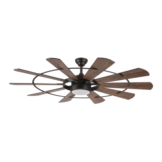
ITEM #1596997
1596998
EUREKA LED
CEILING FAN
MODEL #EUK60BNK10LRS
EUK60BZ10LRS
Español p. 17
ATTACH YOUR RECEIPT HERE
Purchase Date
Questions, problems, missing parts? Before returning to your retailer, call our customer service
department at
1-800-527-1292, 8:30 a.m. - 5 p.m., CST, Monday - Friday.
1
Advertisement
Table of Contents

Related Manuals for LOWES EUREKA Series


Summary of Contents for LOWES EUREKA Series
- Page 1 ITEM #1596997 1596998 EUREKA LED CEILING FAN MODEL #EUK60BNK10LRS EUK60BZ10LRS Español p. 17 ATTACH YOUR RECEIPT HERE Purchase Date Questions, problems, missing parts? Before returning to your retailer, call our customer service department at 1-800-527-1292, 8:30 a.m. - 5 p.m., CST, Monday - Friday.
-
Page 2: Table Of Contents
TABLE OF CONTENTS Safety Information ......................... 2 Package Contents ........................ 4 Hardware Contents ........................... 5 Preparation ........................... 5 Initial Installation ........................5 Wiring ..........................11 Final Installation ........................10 Operating Instructions ......................13 Care and Maintenance ......................14 Troubleshooting ........................15 Limited Lifetime Warranty .................... - Page 3 SAFETY INFORMATION WARNING When mounting fan to a ceiling outlet box, use a METAL octagonal outlet box; do NOT use a plastic outlet box. Secure the outlet box directly to the building structure. The outlet box and its support must be able to support the moving weight of the fan (at least 35 lbs.). To avoid personal injury, the use of gloves may be necessary while handling fan parts with sharp edges.
-
Page 4: Package Contents
PACKAGE CONTENTS PART DESCRIPTION PART DESCRIPTION QUANTITY QUANTITY Mounting Bracket Yoke Cover Canopy Mounting Screw Motor Assembly (preassembled) Blade Downrod Blade Bracket Pin (preassembled) Blade Bar Clip (preassembled) Shade Canopy Remote Pack Canopy Cover IMPORTANT REMINDER: You must use the parts provided with this fan for proper installation and safety. -
Page 5: Hardware Contents
HARDWARE CONTENTS (shown actual size) Decorative Blade Screw/Washer Qty. 20 Wire + 1 extra Connector Qty. 40 + 1 extra Qty. 3 PREPARATION Before beginning assembly of product, make sure all parts are present. Place motor on carpet or on foam to avoid damage to finish. - Page 6 INITIAL INSTALLATION Determine mounting method to use. A. Standard mount B. Angle mount IMPORTANT: If using the angle mount, ensure the ceiling angle is not steeper than 19°. NOTE: Closemount option is not available for this fan. 19° max. *Helpful Hint: Downrod-style mounting is best suited for ceilings 8 ft.
- Page 7 INITIAL INSTALLATION Remove pin (D) and clip (E) from downrod (C). Partially loosen preassembled set screws and nuts in yoke at top of motor assembly (I). Set Screw Yoke 6. Insert downrod (C) through canopy (F), canopy cover (G) and yoke cover (H). NOTE: Canopy cover (G) must be turned with the shiny side toward the motor assembly (I).
- Page 8 INITIAL INSTALLATION DANGER: To reduce the risk of serious bodily injury, DO NOT use power tools to assemble the blades (J). If overtightened, blades (J) may crack and break. Select five blades (J) to attach the five blade brackets (K). Place one blade bracket (K) on top of blade (J) aligning the two biggest of four holes at top of blade (J).
- Page 9 INITIAL INSTALLATION Attach one of the remaining five blades (J) to the V-shaped V-shaped blade arms on the motor assembly (I) blade arm using two blade screws/washers (AA) and two decorative nuts (BB). Repeat step for the other four remaining blades (J). Hardware Used Blade Screw/Washer x 10...
- Page 10 INITIAL INSTALLATION Depending on the length of downrod you use, you may need to cut the lead wires back to simplify the wiring. If you decide to cut back the lead 8 in. wires, it is suggested you do so in the following manner: Hanging Take the lead wires and make sure you have...
-
Page 11: Wiring
WIRING WARNING: To reduce the risk of fire, electrical shock or personal injury, wire connectors provided with this fan are designed to accept only one 12-gauge house wire and two lead wires from the fan. If your house wire is larger than 12-gauge or there is more than one house wire to connect to the corresponding fan lead wires, consult an electrician for the proper size wire connectors to use. -
Page 12: Final Installation
FINAL INSTALLATION Align slots on shade (M) with protrusions on underside of motor assembly (I). Turn shade (M) clockwise until it no longer turns. NOTE: Pull down gently on the shade (M) to make sure it is secured completely. Slot Protrusion If you wish to use the remote control bracket from remote pack (N) on a wood surface, install... -
Page 13: Operating Instructions
OPERATING INSTRUCTIONS CAUTION: The remote control transmitter can be programmed to multiple receivers or fans. If this is not desired, turn wall switch off to any other programmable receiver or fan. FCC Compliance Notice for Remote Control and LED Light Kit Modifications not approved by the party responsible for compliance could void the user's authority to operate the equipment. -
Page 14: Care And Maintenance
OPERATING INSTRUCTIONS 2. Restore electrical power. Within 30 seconds of restoring electrical power, press and hold the button on the remote control transmitter for 5 seconds or until fan beeps. Use the remote control transmitter to test the light and fan functions to confirm the learning process is complete. -
Page 15: Troubleshooting
TROUBLESHOOTING WARNING: Before beginning work, shut off the power supply to avoid electrical shock. PROBLEM POSSIBLE CAUSE CORRECTIVE ACTION Fan does not move. 1. Reverse switch not engaged. 1. Push switch firmly either left or right. 2. Power is off or fuse is blown. 2. -
Page 16: Limited Lifetime Warranty
LIMITED LIFETIME WARRANTY The distributor warrants this fan to be free from defects in workmanship and materials present at time of shipment from the factory for Lifetime limited from the date of purchase. This warranty applies only to the original purchaser. The distributor agrees to correct any defect at no charge or, at our option, replace the ceiling fan with a comparable or superior model.
Need help?
Do you have a question about the EUREKA Series and is the answer not in the manual?
Questions and answers